EP0424338A1 - Linearantrieb - Google Patents
Linearantrieb Download PDFInfo
- Publication number
- EP0424338A1 EP0424338A1 EP90850329A EP90850329A EP0424338A1 EP 0424338 A1 EP0424338 A1 EP 0424338A1 EP 90850329 A EP90850329 A EP 90850329A EP 90850329 A EP90850329 A EP 90850329A EP 0424338 A1 EP0424338 A1 EP 0424338A1
- Authority
- EP
- European Patent Office
- Prior art keywords
- carriage
- chain
- run
- rod
- wheels
- Prior art date
- Legal status (The legal status is an assumption and is not a legal conclusion. Google has not performed a legal analysis and makes no representation as to the accuracy of the status listed.)
- Withdrawn
Links
- 238000006073 displacement reaction Methods 0.000 description 3
- 230000005540 biological transmission Effects 0.000 description 2
- 125000006850 spacer group Chemical group 0.000 description 2
- 235000016936 Dendrocalamus strictus Nutrition 0.000 description 1
- 238000012986 modification Methods 0.000 description 1
- 230000004048 modification Effects 0.000 description 1
Images

Classifications
-
- E—FIXED CONSTRUCTIONS
- E04—BUILDING
- E04H—BUILDINGS OR LIKE STRUCTURES FOR PARTICULAR PURPOSES; SWIMMING OR SPLASH BATHS OR POOLS; MASTS; FENCING; TENTS OR CANOPIES, IN GENERAL
- E04H6/00—Buildings for parking cars, rolling-stock, aircraft, vessels or like vehicles, e.g. garages
- E04H6/08—Garages for many vehicles
- E04H6/12—Garages for many vehicles with mechanical means for shifting or lifting vehicles
- E04H6/18—Garages for many vehicles with mechanical means for shifting or lifting vehicles with means for transport in vertical direction only or independently in vertical and horizontal directions
- E04H6/182—Garages for many vehicles with mechanical means for shifting or lifting vehicles with means for transport in vertical direction only or independently in vertical and horizontal directions using car-gripping transfer means
-
- Y—GENERAL TAGGING OF NEW TECHNOLOGICAL DEVELOPMENTS; GENERAL TAGGING OF CROSS-SECTIONAL TECHNOLOGIES SPANNING OVER SEVERAL SECTIONS OF THE IPC; TECHNICAL SUBJECTS COVERED BY FORMER USPC CROSS-REFERENCE ART COLLECTIONS [XRACs] AND DIGESTS
- Y10—TECHNICAL SUBJECTS COVERED BY FORMER USPC
- Y10T—TECHNICAL SUBJECTS COVERED BY FORMER US CLASSIFICATION
- Y10T74/00—Machine element or mechanism
- Y10T74/18—Mechanical movements
- Y10T74/18568—Reciprocating or oscillating to or from alternating rotary
- Y10T74/18832—Reciprocating or oscillating to or from alternating rotary including flexible drive connector [e.g., belt, chain, strand, etc.]
-
- Y—GENERAL TAGGING OF NEW TECHNOLOGICAL DEVELOPMENTS; GENERAL TAGGING OF CROSS-SECTIONAL TECHNOLOGIES SPANNING OVER SEVERAL SECTIONS OF THE IPC; TECHNICAL SUBJECTS COVERED BY FORMER USPC CROSS-REFERENCE ART COLLECTIONS [XRACs] AND DIGESTS
- Y10—TECHNICAL SUBJECTS COVERED BY FORMER USPC
- Y10T—TECHNICAL SUBJECTS COVERED BY FORMER US CLASSIFICATION
- Y10T74/00—Machine element or mechanism
- Y10T74/18—Mechanical movements
- Y10T74/18568—Reciprocating or oscillating to or from alternating rotary
- Y10T74/18832—Reciprocating or oscillating to or from alternating rotary including flexible drive connector [e.g., belt, chain, strand, etc.]
- Y10T74/18848—Reciprocating or oscillating to or from alternating rotary including flexible drive connector [e.g., belt, chain, strand, etc.] with pulley
Definitions
- the present invention relates to linear gearing.
- the gearing is intended particularly for use in conjunction with automatic parking of vehicles, such as cars, in car-parking buildings in which the cars are transported on a so-called transfer trolley or carriage between a car-receiving or a car-collecting station and a parking place.
- the transfer trolley includes a first carriage which supports a second carriage.
- This second carriage is fixedly connected to the first carrige but movable in relation thereto in the direction of its longitudinal axis.
- a car in a transport position is raised on the second carriage.
- the longitudinal axis of the carriages similar to the longitudinal axis of the car, extend perpendicularly to the longitudinal axis of the shaft.
- the described arrangement functions in the following manner: A car is driven onto the transfer trolley on the bottom floor of the complex, whereafter the trolley is transported horizontally and/or vertically to a position in front of a vacant parking space.
- the second carriage is then displaced in the direction of its longitudinal axis relative to the first carriage into the parking space, where the second carriage deposits the car.
- the second carriage is then moved in over the first carriage, whereafter the whole of the transfer trolley is moved to some other location within the building, in readiness for transporting cars in or out.
- the transfer trolley When a car is to be transported out, the transfer trolley is moved to the parking place concerned, whereafter the second carriage is moved in beneath the car, and lifts the car and moves the same in over the first carriage, whereafter the transfer trolley is moved to a delivery station on the bottom floor of the car-parking building.
- the transfer trolley has a length which corresponds to the width of the shaft.
- the present invention thus relates to linear gearing primarily intended for use in connection with a so-called transfer trolley in automatic parking buildings, said transfer trolley comprising a first carriage which is movable at least horizontally, and a second carriage which is movably connected to the first carriage for movement from a first terminal position in which said second carriage is located within the horizontal confines of the first carriage, to a second terminal position in which the second carriage has been moved in the direction of its longitudinal axis and also in the direction of the longitudinal axis of said first carriage and is located completely or substantially completely outside the first extension in the horizontal plane, and is characterized in that the linear gearing includes at least two chains, namely a first chain which extends between two end wheels which have a first rod or the like extending therebetween, and a second chain which also extends between two end wheels and between which a second rod or the like extends, said chains being arranged in mutually parallel spaced relationship; and in that the first rod is connected with a power source which functions to move the rod in the direction of its longitudinal axis relative
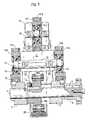
- Reference 3 identifies a motor mounting flange; reference 4 identifies a wedge or key; reference 5 identifies a bearing; reference 106 identifies a chain wheel; reference 7 identifies a shaft; reference 8 identifies a stop screw; reference 105 identifies a chain; reference 10 identifies a U-profile section; reference 11 identifies a thrust rod; reference 12 identifies a shaft; reference 14 identifies a bearing; reference 16A identifies a chain wheel; reference 17A identifies a chain; reference 18 identifies a shaft; reference 19 identifies a thrust rod; reference 16C identifies a chain wheel; reference 17B identifies a chain; references 20A, 20B, 20C, 20D identify attachment devices; reference 21 identifies a screw; reference 22 identifies a spacer; reference 23 identifies a slide profile; reference 24 identifies a spacer tube; reference 25 identifies
- Figure 2 is a side view of the inventive arrangement.
- the invention is concerned with a linear gearing intended primarily for use with a so-called transfer trolley in automatic parking buildings, this transfer trolley including a first carriage which can be moved in at least a horizontal direction, and a second carriage which is movably connected to the first carriage.
- the reference 101 identifies the first carriage and the reference 102 the second carriage.
- the carriages are illustrated highly schematically.
- the linear gearing is located between the carriages 101, 102.
- the second carriage can be moved relative to the first carriage, by bans of said gearing, from a first end position, shown in the upper half of Figure 1, in which the second carriage is located within the horizontal confines or extension of the first carriage, to a second end position, shown in the bottom half of Figure 1, in which the second carriage has been moved in the direction of the longitudinal axis of the first carriage and is located completely outside, or substantially completely outside the extension or confines of the first carriage in the horizontal plane.
- the linear gearing includes two chains, namely a first chain 17A which runs between two end wheels 16A, 16B between which a first body 11 or the like extends, and a second chain 17B which also runs between two end wheels 16C, 16D, between which a second rod 19 or the like extends.
- the chains are arranged in mutually parallel spaced relationship.
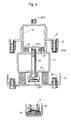
- the first chain 17A comprises two mutually parallel chains, as will be seen from Figure 3.
- the first rod 11 is connected to a power source 103 which functions to move the rod 11 in the direction of its longitudinal axis in relation to the first carriage 1, as shown by the arrow 104 in Figure 1.
- the point of connection is referenced E in Figure 1 and 2, and with the reference sign 20E in Figure 4. That run or part of the second chain 17B which is remote from the first chain 17A is attached to the second carriage 102.
- the point of attachment is referenced D in Figures 1 and 2, and with the reference 20D in Figure 4.
- the second rod 19 is connected to that run or part of the first chain 17A which faces towards the said run or part of the second chain 17B.
- the point of connection is referenced B in Figures 1 and 2, and with the reference 20B in Figure 4.
- That run or part of the second chain 17B which faces towards said run or part of the first chain 17A is attached to the first rod 11.
- the point of attachment is referenced A in Figures 1 and 2, and with the reference 20A in Figure 4.
- That run or part of the first chain 17A which is remote from the second chain 17B is attached to the first carriage 101.
- the point of connection is referenced C in Figure 1 and 2, and with the reference 20C in Figure 4.
- the connections A, B, C, D and E between the first and second chain parts, the first and the second rod and the first and second carriage respectively are located essentially along a straight line which extends perpendicularly to the longitudinal axes of the rods, approximately centrally between said wheels, as will be seen from Figure 2.
- the power source includes a third chain 105 which runs between two wheels 106, 107.
- This chain 105 is placed between the first chain 17A and the first carriage 101.
- the power source includes a motor, not shown, preferably an hydraulic motor which is intended to drive one, 106, of the last-mentioned wheels.
- the linear gearing operates in the following manner:
- the power source 103 i.e. the chain 105 with associated motor, drives the first rod 11 to the position E′ shown to the right in Figure 1, via the attachment E.
- the lower chain 17A is connected to the first carriage 101, through the attachment C, the upper run or part of the bottom chain 17A, including the attachment B, will be driven to the right in Figure 1.
- the second rod 19 will therewith be moved to the right in Figure 1.
- the bottom run of the upper chain 17B is connected to the lower rod 11, by means of the attachment A, the upper chain will also be driven to the right in relation to the upper rod 19.
- the attachment D is therewith driven to the position referenced D′.
- This gearing arrangement provides a four fold transmission between movement of the third chain 105 and movement of the attachment D.
- the invention thus provides a stable, compact and operationally reliable gearing which solves completely the problems defined in the introduction.
- the chains can be arranged horizontally adjacent one another, or in some other orientation.
- the illustrated power source comprises a chain and a hydraulic motor, it will be understood that the power source may comprise a hydraulic piston-cylinder device mounted between the attachment E and the first carriage and functioning to displace the first rod.
- the gearing may also be expanded to include a further chain and rod or further chains and rods which are connected to the second chain (17A) of the illustrated embodiment, so as to provide a four-fold, six-fold or eight-fold transmission system.
Landscapes
- Engineering & Computer Science (AREA)
- Architecture (AREA)
- Mechanical Engineering (AREA)
- Civil Engineering (AREA)
- Structural Engineering (AREA)
- Transmission Devices (AREA)
- Intermediate Stations On Conveyors (AREA)
- Types And Forms Of Lifts (AREA)
Applications Claiming Priority (2)
| Application Number | Priority Date | Filing Date | Title |
|---|---|---|---|
| SE8903404A SE463219B (sv) | 1989-10-16 | 1989-10-16 | Linjaer vaexel saerskilt vid transfervagn i parkeringshus |
| SE8903404 | 1989-10-16 |
Publications (1)
| Publication Number | Publication Date |
|---|---|
| EP0424338A1 true EP0424338A1 (de) | 1991-04-24 |
Family
ID=20377163
Family Applications (1)
| Application Number | Title | Priority Date | Filing Date |
|---|---|---|---|
| EP90850329A Withdrawn EP0424338A1 (de) | 1989-10-16 | 1990-10-09 | Linearantrieb |
Country Status (6)
| Country | Link |
|---|---|
| US (1) | US5103686A (de) |
| EP (1) | EP0424338A1 (de) |
| JP (1) | JPH03183872A (de) |
| FI (1) | FI905071A7 (de) |
| NO (1) | NO904436L (de) |
| SE (1) | SE463219B (de) |
Cited By (1)
| Publication number | Priority date | Publication date | Assignee | Title |
|---|---|---|---|---|
| EP1108660A3 (de) * | 1999-12-15 | 2002-01-30 | Mts Systems Corporation | Traktionsantriebssystem |
Families Citing this family (7)
| Publication number | Priority date | Publication date | Assignee | Title |
|---|---|---|---|---|
| SE505830C2 (sv) * | 1994-08-16 | 1997-10-13 | Sky Park Ic Jr Ab | Transportanordning för att i ett parkeringshus automatiskt transportera ett fordon från en inkörsmodul till en parkeringsplats |
| US7029072B1 (en) | 2002-03-11 | 2006-04-18 | Wirtgen America, Inc. | Modified rumble strip cutter |
| JP4391744B2 (ja) * | 2002-12-27 | 2009-12-24 | 東京エレクトロン株式会社 | 移動式プローブカード搬送装置、プローブ装置及びプローブ装置へのプローブカードの搬送方法 |
| JP4822734B2 (ja) * | 2005-04-12 | 2011-11-24 | 株式会社椿本チエイン | リフター装置 |
| JP4277287B2 (ja) * | 2006-11-27 | 2009-06-10 | 村田機械株式会社 | 天井走行車 |
| US9881824B2 (en) * | 2014-01-07 | 2018-01-30 | Murata Machinery, Ltd. | Transfer apparatus and control method thereof |
| CN108999445B (zh) * | 2018-10-17 | 2020-07-31 | 常州工学院 | 一种双转换双排多层立体式停车装置及其车辆停取方法 |
Citations (6)
| Publication number | Priority date | Publication date | Assignee | Title |
|---|---|---|---|---|
| CH427216A (fr) * | 1964-06-25 | 1966-12-31 | Peter Gilbert | Installation de parcage |
| CH442078A (de) * | 1963-11-28 | 1967-08-15 | Bofors Ab | Ladevorrichtung |
| DE1277546B (de) * | 1962-03-03 | 1968-09-12 | Maschf Augsburg Nuernberg Ag | Transportwagen mit Eigenantrieb zum selbsttaetigen Ein- und Ausfahren von Kraftwagen in die bzw. aus den Boxen von mechanischen Garagen |
| DE2032202A1 (de) * | 1969-07-23 | 1971-02-04 | Bosi, Angelo, Reda, Faenza (Italien) | Autoparkanlage |
| DE3328889A1 (de) * | 1983-08-10 | 1985-02-28 | Hörmann KG Antriebs- und Steuerungstechnik, 4834 Harsewinkel | Geraet zur ueberfuehrung einer rotatorischen in eine translatorische bewegung |
| SE459110B (sv) * | 1988-04-14 | 1989-06-05 | Sky Park Ab | Hiss- och transportanordning foer fordon |
Family Cites Families (7)
| Publication number | Priority date | Publication date | Assignee | Title |
|---|---|---|---|---|
| US3732742A (en) * | 1969-11-25 | 1973-05-15 | Supreme Equip & Syst | Random access store for cards, file folders and the like |
| US3677099A (en) * | 1970-09-09 | 1972-07-18 | Gemco Electric Co | Machine control |
| FR2429061A1 (fr) * | 1978-06-23 | 1980-01-18 | Pont A Mousson | Machine d'extraction de tuyaux centrifuges |
| DE2834415B1 (de) * | 1978-08-05 | 1979-11-22 | Karl Hehl | Vorrichtung zur wegabhaengigen Steuerung von Funktionsablaeufen einer Spritzgiessmaschine |
| FR2512909B1 (fr) * | 1981-09-15 | 1987-02-20 | Renault | Mecanisme de translation rectiligne a poulies et courroies |
| SE437188B (sv) * | 1984-05-07 | 1985-02-11 | Jan Ekman | Anordning av det slag som innefattar tva teleskopiskt samordnade organ |
| US4705455A (en) * | 1985-12-23 | 1987-11-10 | United Technologies Corporation | Convergent-divergent film coolant passage |
-
1989
- 1989-10-16 SE SE8903404A patent/SE463219B/sv not_active IP Right Cessation
-
1990
- 1990-10-09 EP EP90850329A patent/EP0424338A1/de not_active Withdrawn
- 1990-10-12 US US07/597,520 patent/US5103686A/en not_active Expired - Fee Related
- 1990-10-15 FI FI905071A patent/FI905071A7/fi not_active Application Discontinuation
- 1990-10-15 NO NO90904436A patent/NO904436L/no unknown
- 1990-10-16 JP JP2277582A patent/JPH03183872A/ja active Pending
Patent Citations (6)
| Publication number | Priority date | Publication date | Assignee | Title |
|---|---|---|---|---|
| DE1277546B (de) * | 1962-03-03 | 1968-09-12 | Maschf Augsburg Nuernberg Ag | Transportwagen mit Eigenantrieb zum selbsttaetigen Ein- und Ausfahren von Kraftwagen in die bzw. aus den Boxen von mechanischen Garagen |
| CH442078A (de) * | 1963-11-28 | 1967-08-15 | Bofors Ab | Ladevorrichtung |
| CH427216A (fr) * | 1964-06-25 | 1966-12-31 | Peter Gilbert | Installation de parcage |
| DE2032202A1 (de) * | 1969-07-23 | 1971-02-04 | Bosi, Angelo, Reda, Faenza (Italien) | Autoparkanlage |
| DE3328889A1 (de) * | 1983-08-10 | 1985-02-28 | Hörmann KG Antriebs- und Steuerungstechnik, 4834 Harsewinkel | Geraet zur ueberfuehrung einer rotatorischen in eine translatorische bewegung |
| SE459110B (sv) * | 1988-04-14 | 1989-06-05 | Sky Park Ab | Hiss- och transportanordning foer fordon |
Cited By (1)
| Publication number | Priority date | Publication date | Assignee | Title |
|---|---|---|---|---|
| EP1108660A3 (de) * | 1999-12-15 | 2002-01-30 | Mts Systems Corporation | Traktionsantriebssystem |
Also Published As
| Publication number | Publication date |
|---|---|
| US5103686A (en) | 1992-04-14 |
| SE463219B (sv) | 1990-10-22 |
| NO904436D0 (no) | 1990-10-15 |
| SE8903404D0 (sv) | 1989-10-16 |
| FI905071A7 (fi) | 1991-04-17 |
| FI905071A0 (fi) | 1990-10-15 |
| NO904436L (no) | 1991-04-17 |
| JPH03183872A (ja) | 1991-08-09 |
Similar Documents
| Publication | Publication Date | Title |
|---|---|---|
| US4986714A (en) | Vehicle elevator and conveyor arrangement | |
| EP0275004B1 (de) | Automatische Parkgarage | |
| MY113184A (en) | An arrangement for automatically transporting a vehicle from a drive-in module to a parking place in a vehicle parking building | |
| EP0386170B1 (de) | Mehrstöckiges autoparkhaus | |
| US5103686A (en) | Linear gearing | |
| US3987912A (en) | Movable vehicle parking towers | |
| JP2000504383A (ja) | 車両および箱入り商品の駐車および荷扱い用システムに関連する改善 | |
| CN112688505A (zh) | 磁悬浮长定子线圈敷设车辆系统 | |
| EP0380711A1 (de) | Mehrstöckige Garage | |
| US2707054A (en) | Parking apparatus | |
| EP0146176A2 (de) | Hebbares Plattformgerät zur Abstellung und Unterbringung von Pkws | |
| US3688922A (en) | Garage for the storage of vehicles | |
| WO2006054124A1 (en) | Storage system | |
| JP3329134B2 (ja) | 可動体使用の搬送設備 | |
| JP3178771B2 (ja) | 連立型立体駐車装置 | |
| KR100186358B1 (ko) | 중간승입방식 주차설비의 승입장치 | |
| JP2701973B2 (ja) | エレベータ装置 | |
| JPH0952678A (ja) | 自走式エレベーター | |
| JPH0467551B2 (de) | ||
| KR910001079B1 (ko) | 밀집 주차 방법 및 장치 | |
| JPH0756177B2 (ja) | 自動車駐車装置におけるパレットの水平移送装置 | |
| JPH0457555B2 (de) | ||
| SU779200A1 (ru) | Адресное устройство грузовых тележек напольного конвейера | |
| JPS6324761Y2 (de) | ||
| JPH02252867A (ja) | 立体駐車場の車搬送装置 |
Legal Events
| Date | Code | Title | Description |
|---|---|---|---|
| PUAI | Public reference made under article 153(3) epc to a published international application that has entered the european phase |
Free format text: ORIGINAL CODE: 0009012 |
|
| AK | Designated contracting states |
Kind code of ref document: A1 Designated state(s): AT BE CH DE DK ES FR GB GR IT LI LU NL SE |
|
| 17P | Request for examination filed |
Effective date: 19910925 |
|
| 17Q | First examination report despatched |
Effective date: 19920611 |
|
| STAA | Information on the status of an ep patent application or granted ep patent |
Free format text: STATUS: THE APPLICATION IS DEEMED TO BE WITHDRAWN |
|
| 18D | Application deemed to be withdrawn |
Effective date: 19930515 |