EP0424818B1 - Ofen und Heizeinheit für diesen Ofen - Google Patents
Ofen und Heizeinheit für diesen Ofen Download PDFInfo
- Publication number
- EP0424818B1 EP0424818B1 EP90120092A EP90120092A EP0424818B1 EP 0424818 B1 EP0424818 B1 EP 0424818B1 EP 90120092 A EP90120092 A EP 90120092A EP 90120092 A EP90120092 A EP 90120092A EP 0424818 B1 EP0424818 B1 EP 0424818B1
- Authority
- EP
- European Patent Office
- Prior art keywords
- bends
- slot
- resistance element
- block
- resistance
- Prior art date
- Legal status (The legal status is an assumption and is not a legal conclusion. Google has not performed a legal analysis and makes no representation as to the accuracy of the status listed.)
- Expired - Lifetime
Links
Images

Classifications
-
- H—ELECTRICITY
- H05—ELECTRIC TECHNIQUES NOT OTHERWISE PROVIDED FOR
- H05B—ELECTRIC HEATING; ELECTRIC LIGHT SOURCES NOT OTHERWISE PROVIDED FOR; CIRCUIT ARRANGEMENTS FOR ELECTRIC LIGHT SOURCES, IN GENERAL
- H05B3/00—Ohmic-resistance heating
- H05B3/62—Heating elements specially adapted for furnaces
- H05B3/64—Heating elements specially adapted for furnaces using ribbon, rod, or wire heater
-
- H—ELECTRICITY
- H05—ELECTRIC TECHNIQUES NOT OTHERWISE PROVIDED FOR
- H05B—ELECTRIC HEATING; ELECTRIC LIGHT SOURCES NOT OTHERWISE PROVIDED FOR; CIRCUIT ARRANGEMENTS FOR ELECTRIC LIGHT SOURCES, IN GENERAL
- H05B3/00—Ohmic-resistance heating
- H05B3/62—Heating elements specially adapted for furnaces
- H05B3/66—Supports or mountings for heaters on or in the wall or roof
Definitions
- the present invention relates to furnaces and kilns for heat treating materials at relatively high temperatures and to combination thermal insulating and heating units which are used in forming the enclosure for such furnaces and kilns, hereafter referred to as "furnaces.”
- the present invention is an improvement upon ovens utilizing the thermal insulating and heating unit of the present inventor's United States Patent No. 4,575,619 entitled ELECTRICAL HEATING UNIT WITH SERPENTINE HEATING ELEMENT granted on March 11, 1986, and an improvement on such thermal insulating and heating units.
- That patent describes a combination thermal insulating and heating unit in which a serpentine heating element is disposed on the floor of a slot which extends into a block of ceramic fibers.
- the patent also describes the process of making such a combination thermal insulating and heating unit of ceramic fibers in which a serpentine heating element is supported on a narrow elongated strip which rests on a liquid permeable screen at the bottom of a vacuum box, the heating element having reverse bends protruding from both sides of the elongated strip.
- a slurry of ceramic fibers, water and a binder is then poured into the vacuum box covering the serpentine heating element to a satisfactory depth.
- a portion of the water and binder of the slurry is then permitted to drain from the vacuum box, and thereafter a vacuum is drawn below the screen to cause more of the water and binder of the slurry to drain through the screen.
- the vacuum also causes the fibers to pack tightly forming a mat with sufficient integrity to permit removal from the vacuum box.
- the thin strip is then removed exposing the central portions of the heating element on the bottom or floor of an elongated slot formed by the supporting strip for the heating element.
- the mat is then cured in an oven to form a combination thermal insulation and heating element in which the element is disposed at the bottom or floor of a slot.
- the serpentine heating element is securely mounted on the block of ceramic fibers by outwardly extending bends which are embedded in the ceramic fiber block, but a portion of the heating element is directly exposed to the interior of the enclosure by the slot to provide efficient heat transfer. While this construction has proven to provide a superior mounting construction for the heating element on the ceramic fiber mat and good heat transfer, it places restrictions on the heating element itself which have made it difficult to increase the heat transferred from a given area of the combination thermal insulating and heating unit. As a result of these restrictions, efforts to shorten the time required to bring a furnace constructed with such thermal insulating and heating units to operating temperature have been frustrated. It is a primary object of the present invention to provide a furnace utilizing combination insulating and heating units with electrical heating elements anchored in a ceramic fiber block in which the furnace can be brought to operating temperature in a significantly shorter time than prior furnaces.
- This technique for increasing the heat liberated from a given area of heating element is generally not practical due to the cost of increasing the potential of the power source, and the thermal strain placed upon the heating element. There is a limit of how many watts per square cm (inch) of wire surface area can be liberated. If the watt input is too high the heating wire will burn out.
- the most practical technique for increasing the heat transfer from a given area of a heating unit operating above 700°C. is to increase both the electrical current and the area of the heating element.
- the current through the electrical heating element can be increased by decreasing the resistance of the element or increasing the potential of the power source, but the area of the electrical resistance heating element of the inventor's Patent No. 4,575,619 may not readily be increased.
- These electrical resistance elements require a plurality of 180 degree bends in opposite directions, and accordingly the elements must be of a material and size to permit formation. Further, the 180 degree bends are preferably on as short a radius as possible in order to maximize the length of the heating element disposed on a unit of area of the ceramic pad.
- the elements are constructed of solid resistance wire material to maximize the surface area for a given resistance per unit of length, and hence are subject to cracking during formation. As a result, it has proven to be difficult to increase the thermal output per unit of area of the combination thermal insulating and heating units constructed in the manner of United States Patent No. 4,575,619.
- French Patent 770,071 shows the use of an electrical resistance element comprising two legs, each of which has a serpentine shape, for increasing the thermal output from the element.
- the two legs are in series with one another, the increased heating is obtained from the use of one or more of the previously described techniques not suitable for use with the heating units of U.S. Patent 4,575,619.
- combination thermal insulating and heating units for use in furnaces operated at temperatures in excess of 700°C. may be constructed with a rigid block of ceramic fibers provided with an elongated slot extending therein and a plurality of elongated serpentine electrical resistance elements disposed within the slot and adjacent to the floor of the slot.
- Each of the resistance elements has a first plurality of U-shaped bends disposed on one side of the axis of elongation of the heating element a second plurality of U-shaped bends disposed on the other side of the axis of elongation of the heating element, and the bends engage the block.
- the heating elements may be electrically interconnected at their respective ends and connected to a power source to produce up to the maximum radiant heat transfer per unit of area for each of the heating elements. Further, a plurality of substantially identical heating elements may be stacked one above the other on the narrow strip in the process for making heating elements described in United States Patent No. 4,575,619, the ends of the elements welded together, and the process completed as described to fabricate a combination thermal insulating and heating unit capable of operation at temperatures above 700°C. The inventor has found that two serpentine electrical resistance elements stacked together in the improved insulating and heating unit form a particularly desirable unit and transfer twice the heat of a unit utilizing only one such heating element.
- the inventor has also found that a furnace utilizing such an improved combination thermal insulating and heating unit can be brought to operating temperature in an unexpectedly short time, even when that temperature is in excess of 1OO0°C.
- a combination thermal insulating and heating unit for use in a furnace adapted to operate at temperatures above 700°C. comprising a mass of ceramic fibers bound together to form a rigid block with a surface adapted to face the interior of a furnace, said fibers being electrically nonconducting and the block being an electrical and thermal insulator, said block having an elongated slot extending therein from the surface, said slot forming opposed walls on opposite sides thereof extending into the block and a floor disposed between the walls, a first elongated electrical resistance element identical to said first resistance element disposed within the slot adjacent to the floor thereof and extending between first and second ends of said slot, said first resistance element having a first plurality of bends disposed on one side of the axis of elongation of the resistance element and engaging the block at one of the opposed walls of the slot, said first resistance element having a second plurality of bends disposed on the other side of the axis of elongation of the resistance element and engaging
- FIG. 1 illustrates a furnace 4 constructed according to the teachings of the present invention.
- the furnace 4 has a frame 6 which supports an interior thermal insulating liner 8.
- the insulating liner 8 has at least one combination thermal insulating and heating unit 10 constructed according to the present invention.
- the thermal insulating and heating unit 10 has a molded block 12 of thermal insulating material.
- the block 12 is preferably molded of inorganic ceramic fibers of the type disclosed in United States Patent No. 3,500,444 to W. J. Hesse, et al.
- high refractory compositions such as silica or quartz, magnesia, alumina-silica, produce inorganic fibers which exhibit resistance to deterioration at temperatures up to the order of 1400°C.
- Blocks made of such compositions are relatively porous and provide excellent thermal insulation. Further, such blocks are readily molded into various shapes and are thus particularly suitable for forming the walls of a furnace.
- the block 12 has two flat parallel surfaces 14 and 16, a face 18 extending between the surfaces 14 and 16, sides 20 and 22, and a back, not shown. Sides 20 and 22 are provided with outwardly extending quadrangular steps 24 and 26 which mate with recesses 27 in adjacent portions of the liner 8 to form a closed liner 8 for the furnace 4.
- the surfaces 14 and 16 are flat in the illustrated embodiment, but may be curved to match the contour of the liner 8.
- the block 12 is provided with a plurality of slots 28 which extend into the surface 16 of the block, the slots 28 being elongated and having parallel walls 30 and 32, as illustrated in Figures 2 and 4.
- slots 28A in block 12A have oblique opposed walls 30A and 32A.
- adjacent slots 28 are spaced by strips 34 and are disposed parallel to each other.
- Each of the slots 28 extends into the block 12 from the surface 16 essentially the same distance and forms a flat surface or floor 36 remote from the surface 16.
- a pair of serpentine heating elements 38A and 38B are disposed on the floor 36 of the slot 28 with one element 38B disposed directly above the other element 38A and vertically aligned with element 38A.
- the heating elements 38A and 38B are identical, and each of said heating elements is an elongated, hollow electrical resistance wire 40 with bends 42 and 44.
- the elements 38A and 38B each have two linear identical sections 39A and 39B which are disposed parallel to each other and designed to be accommodated by two adjacent slots 28.
- the two sections 39A and 39B are an integral unit coupled at one end 43A by a plurality of loops 41.
- the bends 42 form a first group and are disposed on one side of the axis of elongation 45 and are separated from each other by a fixed distance along the axis 45.
- the bends 44 form a second group and are disposed on the other side of the axis of elongation and are separated from each other by the same fixed distance. Each of the bends 44 of the second group is located between adjacent bends 42 of the first group, except for the last bend at each end of the wire 40. Each of the bends 42 and 44 have the same radius of curvature, and each bend 42 is separated from the bend 44 by a straight connecting section 46 of resistance wire.
- the connecting sections 46 are of equal length, thereby positioning the bends 42 of the first group tangent to a plane 49A perpendicular to the surface 16 and parallel to the axis 45 of elongation of the heating element 38A or 38B, and positioning the bend 44 of the second group tangent to a plane 49B perpendicular to the surface 16 and parallel to the axis 45 of elongation of the heating element 38A or 38B.
- the planes 49A and 49B traverse the strips 34 on opposite sides of the slot 28, so that a portion of each bend 42 and 44 is embedded in the block 12.
- each of the bends 42 and 44 encompasses an angle of 180° in the preferred construction illustrated in the figures, and, therefore, the straight sections 46 are parallel to each other and perpendicular to the axis 45 of elongation of the heating elements 38A and 38B.
- the heating elements 38A and 38B approach the maximum mass of heating element per unit of length for a given diameter wire 40 and bends 42 and 44 of a given radius of curvature.
- the invention may be practiced however using bends 42 and 44 of less than 180°, and the sections between each bend 42 and 44 may be curved rather than straight.
- the wire 40 as illustrated in Figure 3 is cylindrical in shape and hollow to maximize surface area for a given resistance per unit of length, but the wire may be flat, square, rectangular, or the like.
- the sections 39A and 39B of the heating elements 38A and 38B are disposed in adjacent slots 28 and each section is disposed in one of the slots 28 in abutment with the floor 36 thereof.
- the straight connection sections 46 of the resistance elements 38A and 38B extend through the walls 30 and 32, and the bends 42 and 44 of each element 38A and 38B are embedded in the strips 34 of the block 12 adjacent to each slot 28.
- the heating elements 38A and 38B are retained in assembly with the block 12 due to the engagement of the fibers of the block 12 with the bends 42 and 44 of the heating elements 38A and 38B.
- a portion of the connecting sections 46 of the heating elements 38A and 38B can be embedded in the walls 30 and 32 of the block 12.
- the bends 42 and 44 should merely abut the walls 30 and 32 of the slot 28.
- the block 12 has little strength, and the heating element 38A or 38B may exhibit considerable mass.
- the depth of penetration of the bends 42 and 44 of each heating element 38A and 38B into the block 12 changes upon heating of the resistance elements 38A and 38B.
- Expansion of the heating elements 38A and 38B occurs along the entire axis of the element, but expansion of the connecting sections 46 force the bends 42 and 44 against the fibers of the block 12, thereby causing the bends to further penetrate the strips 34.
- the block 12 however has little shear strength, and the expansion of the resistance element produces a compressional force against the block 12 which significantly aids in retaining the heating elements 38A and 38B in attachment with the block 12, particularly at elevated temperatures.
- each of the bends 42 and 44 is embedded into the block 12 by a distance generally no greater than one-fourth of the distance between the bends 42 and the bends 44, so that at least one-half of the connection section 46 of the resistance element 38A or 38B is disposed on the floor 36 of the slot 28.
- Adjacent slots 28 must be separated by sufficient distance so that the strip 34 between the slots provides adequate electrical insulation between adjacent electrical heating elements 38A and 38B.
- the ceramic fibrous material of the block 12 is an electrical insulator, but the electrical insulating properties depend upon the associated environment and temperature in which the block is used.
- each slot 28 is disposed in the flat surface 16 of a block 12, each slot extending completely from the front surface 18 of the block to the back surface to a depth of 0.63 cm (1/4) inch at the floor 36.
- Each slot 28 has a width measured perpendicular to the walls 30 and 32 of 1.59 cm (5/8 inch).
- the electrical resistance heating elements 38A and 38B are constructed of 15 gauge Kanthal A-1 heating element wire with a cylindrical cross section and a resistance of 0.05 (0.12) ohms per cm (inch).
- the bends 42 of the heating elements 38A and 38B extend to plane 49A and the bends 44 extend to the plane 49B, and the plans 49A and 49B are displaced for each other by distance of 2.22 cm (7/8 inch), and hence approximately 0.32 cm (1/8 inch) of each bend 42 and 44 is embedded in the block 12.
- the ends 43B of the elements 38A and 38B have depending stubs 50 which extend normally from the plane of the element.
- the two elements 38A and 38B are electrically and mechanically interconnected by connecting the stubs 50 of the two elements 38A and 38B, as by a weld 52 illustrated in Figure 4.
- the total length of No. 15 gauge Kanthal A-1 heating wire 40 is 2.05 m (6 foot, 9 inches), including both sections 39A and 39B.
- Each of the sections 39A and 39B is 33 cm (13 inches) in length, and the element is otherwise as described above.
- the element is designed to operate in a furnace at 1300°C, and a controller 54 is connected electrically between a direct current power source 56 and the interconnected stubs 50 of the heating elements 38A and 38B to limit the furnace temperature to the control value.
- a single element 38A with two sections 39A and 39B was subjected to 3163.4 watts by flowing 13.6 amperes through the element with a direct current power source of 232.6 volts.
- a part of the thermal insulating liner of a particular furnace, such as described in Figure 1 the furnace was heated from room temperature to 1199°C. in a period of 25 minutes.
- the element was loaded to transfer 4.72 (30.5) watts per square cm (inch) of element surface under these conditions.
- the heat insulating and heating unit 10 with a dual heater unit 38A and 38B heated the same furnace as described above to a temperature of 1200°C. from room temperature in about 5 and 1/2 minutes.
- the reduction in the time required to bring the temperature of that particular furnace from 25 minutes to 5 and 1/2 minutes exceeds expectations.
- the temperature of the heating elements 38A and 38B are not greatly above the furnace temperature, thus indicating that the heat produced by the electrical energy is being transferred from the element into the furnace.
- the heating elements 38A and 38B stabilized at 1246°C. with a stable furnace temperature of 1200°C., a temperature only 6°C. over that of a singly element 38A. Stability was obtained by operating the furnace for a period of 60 minutes at 1200°C. before the readings were taken. It is believed that the elements 38A and 38B transfer heat almost entirely by radiation at these temperatures, and accordingly, the presence of element 38B does not appreciably affect the operation of the element 38A.
- the heater wire 40 is not electrically insulated, and that the two heating elements 38A and 38B are in contact at many points along the elements. Arcing between the elements 38A and 38B does not occur, because the elements are at approximately the same electrical potential at all points along the elements. Elimination of arcing is assured by stacking one element 38B on the other element 38A. The mechanical position of the elements tends to be maintained as a result of welding the ends of the element 38B on the ends of the element 38A, and these welds provide the electrical connection between the elements 38A and 38B.
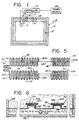
- Figure 6 illustrates, somewhat diagrammatically, apparatus for producing the panels for Figures 1, 2, 4 and 5.
- Figure 6 a frame 68 which is provided with a horizontal bottom 70.
- the bottom 70 supports a plurality of elongated upwardly rising strips 72 forming plateaus. Each of the strips has a flat rectangular upper surface 74.
- the bottom 70, entire strips 72 and upper surface 74 are of porous material.
- Frame 68 is mounted on a suction box 76 which extends below the bottom 70 of the frame.
- the suction box 76 has an orifice 78 which is adapted to be connected to a means not shown, to evacuate the suction box 76.
- the opposite ends 43A and 43B of a pair of resistance heating elements 38A and 38B are welded together and a pair of the assembled elements 38A and 38B are then placed on each strip 74, with the bends 42 and 44 overlapping opposite sides of the strip 74.
- the frame 68 is filled to a level above the resistance elements 38A and 38B with a slurry of water, binder, and inorganic fibers of the type described in United States Patent No. 3,500,444 of W. K. Hesse, et al.
- the liquid portion of the slurry is permitted to flow through the bottom 70 of the frame 68, and suction is applied to the suction box 76 to withdraw a larger portion of the liquid portion of the slurry on the bottom 70.
- the porous strip 72 permits the passage of the liquid portion of the slurry, and the fibers will be deposited upon the resistance heating elements 38A and 38B and the walls of the strip 72. It will be noted in Figure 6 that a plurality of strips 72 are employed to mold in situ a plurality of electrical heating elements 38A and 38B. The block thus formed is thereafter removed from the frame 68 and dried.
Landscapes
- Resistance Heating (AREA)
- Furnace Details (AREA)
- Vertical, Hearth, Or Arc Furnaces (AREA)
- Furnace Housings, Linings, Walls, And Ceilings (AREA)
- Control Of High-Frequency Heating Circuits (AREA)
- Constitution Of High-Frequency Heating (AREA)
- Electric Stoves And Ranges (AREA)
Claims (8)
- Kombination einer Wärmeisolations- und Heizeinheit (10) zur Verwendung in einem Ofen (4), der zur Funktionsweise bei Temperaturen über 700°C geeignet ist, mit einer Anhäufung von Keramikfasern, die miteinander verbunden sind, so daß sie einen starren Block (12) mit einer Oberfläche (16) bilden, welche in das Innere des Ofens zeigt, wobei die Fasern elektrisch isolierend sind, und wobei der Block einen elektrischen Isolator sowie einen Wärmeisolator darstellt, wobei der Block einen Langschlitz (28) aufweist, der sich darin von der Oberfläche erstreckt, wobei der Schlitz an entgegengesetzten Seiten entgegengesetzte Wände (30, 32) gestaltet, die sich in den Block erstrecken, und mit einem Boden (36), der sich zwischen den Wänden befindet, mit einem ersten langgestreckten elektrischen Widerstandselement (38A), das sich neben dem Boden in dem Schlitz befindet und das sich zwischen ersten und zweiten Enden des Schlitzes erstreckt, wobei das erste Widerstandselement eine erste Mehrzahl von Biegungen (42) aufweist, die sich an einer Seite der Achse (45) der Ausdehnung des Widerstandselementes befinden und die mit dem Block an einer der entgegengesetzten Wände des Schlitzes eingreifen, wobei das erste Widerstandselement eine zweite Mehrzahl von Biegungen (44) aufweist, die sich an der anderen Seite der Achse der Ausdehnung des Widerstandselementes befinden und die mit dem Block an der anderen der entgegengesetzten Wände des Schlitzes eingreifen, wobei die Biegungen der ersten Gruppe elektrisch in Reihe mit den Biegungen der zweiten Gruppe verbunden sind (46), und gekennzeichnet durch ein zweites langgestrecktes elektrisches Widerstandselement (39A), das zu dem ersten Widerstandselement identisch ist, das sich neben dem Boden in dem Schlitz befindet und das sich zwischen dem ersten und zweiten Ende des Schlitzes erstreckt, wobei das zweite Widerstandselement eine erste Mehrzahl von Biegungen aufweist, die sich an einer Seite der Ausdehnungsachse des zweiten Widerstandselementes befinden und die mit dem Block an einer der entgegengesetzten Wände des Schlitzes eingreifen, wobei das zweite Widerstandselement eine zweite Mehrzahl von Biegungen aufweist, die sich an der anderen Seite der Ausdehnungsachse des zweiten Widerstandselementes befinden und die mit dem Block an der anderen der entgegengesetzten Wände des Schlitzes eingreifen, wobei das erste Ende (43B) des zweiten Widerstandselementes elektrisch mit dem ersten Ende des ersten Widerstandselementes verbunden ist, und wobei das zweite Ende des zweiten Widerstandselementes elektrisch mit dem zweiten Ende des ersten Widerstandselementes verbunden ist, wobei die beiden Widerstandselemente somit elektrisch parallel verbunden sind.
- Kombination einer Wärmeisolations- und Heizeinheit nach Anspruch 1, dadurch gekennzeichnet, daß es sich bei den ersten und zweiten Widerstandselementen um langgestreckte, metallische Widerstandselemente handelt.
- Kombination einer Wärmeisolations- und Heizeinheit nach Anspruch 1, dadurch gekennzeichnet, daß es sich bei der ersten Gruppe von Biegungen und der zweiten Gruppe von Biegungen der ersten und zweiten Elemente um Biegungen von im wesentlichen 180 Grad handelt.
- Kombination einer Wärmeisolations- und Heizeinheit nach Anspruch 1, dadurch gekennzeichnet, daß es sich bei den ersten und zweiten Widerstandselementen um hohle, röhrenförmige Elemente handelt.
- Kombination einer Wärmeisolations- und Heizeinheit nach Anspruch 1, dadurch gekennzeichnet, daß wenigstens ein Teil der Biegungen der ersten Gruppe und ein Teil der Biegungen der zweiten Gruppe der ersten und zweiten Widerstandselemente in der einen bzw. in der anderen Wand eingebettet ist.
- Kombination einer Wärmeisolations- und Heizeinheit nach Anspruch 1, dadurch gekennzeichnet, daß die Wände des Schlitzes senkrecht zu der Oberfläche und parallel zueinander sind, wobei die ersten Biegungen der ersten und zweiten Widerstandselemente auf einer ersten Ebene enden, die parallel zu der einen Wand ist, und wobei die zweiten Biegungen der ersten und zweiten Widerstandselemente auf einer zweiten Ebene enden, die parallel zu der anderen Wand des Schlitzes ist.
- Kombination einer Wärmeisolations- und Heizeinheit nach Anspruch 1, dadurch gekennzeichnet, daß die ersten und zweiten Widerstandselemente überlappend angeordnet sind, wobei die ersten und zweiten Enden jedes Widerstandselementes in langgestreckten Stümpfen enden, die sich nebeneinander und quer zu der Achse der Ausdehnung der Widerstandselemente erstrecken, und wobei jedes Stumpfpaar an den ersten und zweiten Enden elektrisch miteinander verbunden ist, um die entsprechenden ersten und zweiten Enden elektrisch miteinander zu verbinden.
- Kombination einer Wärmeisolations- und Heizeinheit zur Verwendung in einem Ofen nach Anspruch 1, dadurch gekennzeichnet, daß eine Mehrzahl dieser Einheiten dazu verwendet wird, an der Innenoberfläche der Umhüllung eines Ofens eine wärmeisolierende Schicht zu gestalten, wobei der Ofen eine Quelle für elektrische Energie umfaßt sowie eine Einrichtung zur Verbindung der Quelle für elektrische Energie über die ersten und zweiten Enden der ersten und zweiten Widerstandselemente, wobei die Verbindungseinrichtung eine Einrichtung zur Regelung des Flusses von elektrischem Strom durch die ersten und zweiten Widerstandselemente umfaßt, und zwar als Reaktion auf die Temperatur in der Umhüllung, so daß die Temperatur in der Umhüllung auf einem vorbestimmten Wert von mindestens 700°C gehalten wird.
Applications Claiming Priority (2)
| Application Number | Priority Date | Filing Date | Title |
|---|---|---|---|
| US42593589A | 1989-10-24 | 1989-10-24 | |
| US425935 | 1989-10-24 |
Publications (2)
| Publication Number | Publication Date |
|---|---|
| EP0424818A1 EP0424818A1 (de) | 1991-05-02 |
| EP0424818B1 true EP0424818B1 (de) | 1994-12-14 |
Family
ID=23688644
Family Applications (1)
| Application Number | Title | Priority Date | Filing Date |
|---|---|---|---|
| EP90120092A Expired - Lifetime EP0424818B1 (de) | 1989-10-24 | 1990-10-19 | Ofen und Heizeinheit für diesen Ofen |
Country Status (5)
| Country | Link |
|---|---|
| US (1) | US5126535A (de) |
| EP (1) | EP0424818B1 (de) |
| JP (1) | JPH0731012B2 (de) |
| AT (1) | ATE115825T1 (de) |
| DE (1) | DE69015114D1 (de) |
Families Citing this family (6)
| Publication number | Priority date | Publication date | Assignee | Title |
|---|---|---|---|---|
| JPH065355A (ja) * | 1992-06-23 | 1994-01-14 | Sakaguchi Dennetsu Kk | 面状発熱体 |
| US5847368A (en) * | 1996-06-20 | 1998-12-08 | Koyo Lindberg Limited | Electric heating unit and method of producing same |
| JP5216356B2 (ja) * | 2008-02-15 | 2013-06-19 | 光洋サーモシステム株式会社 | 電気加熱ユニットおよびその製造方法 |
| CN103017543B (zh) * | 2013-01-07 | 2015-10-21 | 尹彦征 | 一种烧制镉红色釉陶瓷挂盘的电窑 |
| JP6619127B2 (ja) | 2013-10-30 | 2019-12-11 | サンドビック株式会社 | 加熱装置および加熱炉 |
| KR102157476B1 (ko) * | 2018-02-14 | 2020-09-21 | (주)알파플러스 | 진공 증발원용 히터 및 절연체 어셈블리 |
Family Cites Families (19)
| Publication number | Priority date | Publication date | Assignee | Title |
|---|---|---|---|---|
| US1057745A (en) * | 1912-02-05 | 1913-04-01 | Milton M Kohn | Electric heater. |
| US1645867A (en) * | 1926-12-21 | 1927-10-18 | William B Louthan | Electric heating unit |
| US1923644A (en) * | 1932-01-11 | 1933-08-22 | Pittsburgh Res Corp | Electric heating furnace |
| US1910700A (en) * | 1932-01-25 | 1933-05-23 | Lebau Louis | Electric radiant range |
| FR770071A (fr) * | 1934-03-01 | 1934-09-06 | Nouveau système de four électrique | |
| US2708704A (en) * | 1952-04-23 | 1955-05-17 | Lindberg Eng Co | Electric heating coil structure |
| US2896004A (en) * | 1956-03-05 | 1959-07-21 | Lindberg Eng Co | Electric heating furnace and method of heating |
| US2820076A (en) * | 1956-05-21 | 1958-01-14 | Lindberg Eng Co | Electrical heating assembly |
| US2891303A (en) * | 1957-04-29 | 1959-06-23 | Lindberg Eng Co | Electric furnace heating element |
| US3134836A (en) * | 1960-07-11 | 1964-05-26 | Lindberg Eng Co | Electric heating furnace |
| US3500444A (en) * | 1968-01-16 | 1970-03-10 | Johns Manville | Electrical heating unit with an insulating refractory support |
| US4154975A (en) * | 1977-03-04 | 1979-05-15 | Sauder Industries, Inc. | Method and apparatus for supporting electric heating elements in a furnace insulated with ceramic fiber |
| SE7806238L (sv) * | 1977-07-02 | 1979-01-03 | Fischer Karl | Elektriskt stralningsvermeelement, serskilt for glaskeramikkokhell |
| US4161391A (en) * | 1978-03-14 | 1979-07-17 | Allied Chemical Corporation | Melting apparatus |
| SE8002541L (sv) * | 1980-04-02 | 1981-10-03 | Bulten Kanthal Ab | Anordning for uppberande av elektriska motstandselement |
| US4445024A (en) * | 1981-03-24 | 1984-04-24 | Research Technology Canberra Pty. Ltd. | Electric kiln |
| DE3233181C2 (de) * | 1982-09-07 | 1985-08-01 | Bulten-Kanthal GmbH, 6082 Mörfelden-Walldorf | Aus keramischen Fasern vakuumgeformte, elektrische, freistrahlende Widerstands-Heizvorrichtung für Industrieöfen und Verfahren zu deren Herstellung. |
| US4575619A (en) * | 1984-05-08 | 1986-03-11 | General Signal Corporation | Electrical heating unit with serpentine heating element |
| US4829282A (en) * | 1988-01-21 | 1989-05-09 | Btu Engineering Corporation | High efficiency high heat output electrical heater assembly |
-
1990
- 1990-10-19 EP EP90120092A patent/EP0424818B1/de not_active Expired - Lifetime
- 1990-10-19 AT AT90120092T patent/ATE115825T1/de not_active IP Right Cessation
- 1990-10-19 DE DE69015114T patent/DE69015114D1/de not_active Expired - Lifetime
- 1990-10-24 JP JP2284531A patent/JPH0731012B2/ja not_active Expired - Lifetime
-
1991
- 1991-07-22 US US07/734,052 patent/US5126535A/en not_active Expired - Fee Related
Also Published As
| Publication number | Publication date |
|---|---|
| EP0424818A1 (de) | 1991-05-02 |
| JPH0731012B2 (ja) | 1995-04-10 |
| US5126535A (en) | 1992-06-30 |
| ATE115825T1 (de) | 1994-12-15 |
| DE69015114D1 (de) | 1995-01-26 |
| JPH03221784A (ja) | 1991-09-30 |
Similar Documents
| Publication | Publication Date | Title |
|---|---|---|
| EP0160926B1 (de) | Elektrische Heizeinheit mit Heizelement und Verfahren zu seiner Herstellung | |
| CH649621A5 (de) | Elektrische strahlungsheizeinrichtung fuer kochgeraete. | |
| EP0424818B1 (de) | Ofen und Heizeinheit für diesen Ofen | |
| US1923644A (en) | Electric heating furnace | |
| US4380116A (en) | Radiant electrical heater, as well as method and apparatus for the manufacture thereof | |
| US4249888A (en) | Industrial furnace with ceramic insulating modules having internal grid support | |
| EP0612195B1 (de) | Elektrischer Strahlungsheizkörper und Verfahren zu seiner Herstellung | |
| EP0179606B1 (de) | Heizgerät für warmschrumpfende Röhre | |
| CA2190680C (en) | Apparatus for lengthwise graphitization (lwg) of carbon electrode bodies | |
| US4147888A (en) | Electric heating element for electric resistance furnaces | |
| EP0612197B1 (de) | Verfahren zur Herstellung eines elektrischen Strahlungsheizkörpers | |
| JP2023553951A (ja) | コンクリート養生用均一発熱システム | |
| US4669181A (en) | Method for manufacturing an electrical heating unit with serpentine heating elements | |
| JP3500583B2 (ja) | 放射電熱器の製造方法 | |
| CA1087236A (en) | Electric slot furnace | |
| EP1842395A2 (de) | Heizelementstruktur mit effizienter wärmeerzeugung und mechanischer stabilität | |
| EP0814640B1 (de) | Elektrische Heizanordnung und ihr Herstellungsverfahren | |
| US4620309A (en) | Electric furnace construction | |
| US3142717A (en) | Apparatus for producing quartz | |
| JP2803413B2 (ja) | 電気ヒーター並びにその製造方法 | |
| GB2163248A (en) | Insulation of electrical storage heaters | |
| JP2946649B2 (ja) | 真空炉及び真空炉における温度均一化方法 | |
| JPS61119988A (ja) | セラミツクス焼成装置 | |
| CA1105976A (en) | Electric furnace heater assembly | |
| JPH07249475A (ja) | SiC質パネルヒーター |
Legal Events
| Date | Code | Title | Description |
|---|---|---|---|
| PUAI | Public reference made under article 153(3) epc to a published international application that has entered the european phase |
Free format text: ORIGINAL CODE: 0009012 |
|
| AK | Designated contracting states |
Kind code of ref document: A1 Designated state(s): AT DE FR GB IT |
|
| 17P | Request for examination filed |
Effective date: 19910725 |
|
| 17Q | First examination report despatched |
Effective date: 19930309 |
|
| GRAA | (expected) grant |
Free format text: ORIGINAL CODE: 0009210 |
|
| ITF | It: translation for a ep patent filed | ||
| AK | Designated contracting states |
Kind code of ref document: B1 Designated state(s): AT DE FR GB IT |
|
| PG25 | Lapsed in a contracting state [announced via postgrant information from national office to epo] |
Ref country code: FR Effective date: 19941214 Ref country code: AT Effective date: 19941214 |
|
| REF | Corresponds to: |
Ref document number: 115825 Country of ref document: AT Date of ref document: 19941215 Kind code of ref document: T |
|
| REF | Corresponds to: |
Ref document number: 69015114 Country of ref document: DE Date of ref document: 19950126 |
|
| PG25 | Lapsed in a contracting state [announced via postgrant information from national office to epo] |
Ref country code: DE Effective date: 19950315 |
|
| EN | Fr: translation not filed | ||
| PG25 | Lapsed in a contracting state [announced via postgrant information from national office to epo] |
Ref country code: GB Effective date: 19951019 |
|
| PLBE | No opposition filed within time limit |
Free format text: ORIGINAL CODE: 0009261 |
|
| STAA | Information on the status of an ep patent application or granted ep patent |
Free format text: STATUS: NO OPPOSITION FILED WITHIN TIME LIMIT |
|
| 26N | No opposition filed | ||
| GBPC | Gb: european patent ceased through non-payment of renewal fee |
Effective date: 19951019 |
|
| PG25 | Lapsed in a contracting state [announced via postgrant information from national office to epo] |
Ref country code: IT Free format text: LAPSE BECAUSE OF NON-PAYMENT OF DUE FEES;WARNING: LAPSES OF ITALIAN PATENTS WITH EFFECTIVE DATE BEFORE 2007 MAY HAVE OCCURRED AT ANY TIME BEFORE 2007. THE CORRECT EFFECTIVE DATE MAY BE DIFFERENT FROM THE ONE RECORDED. Effective date: 20051019 |