EP0425067A2 - Vorrichtung zum Auftragen eines Beschichtungsmittels auf einer Substratoberfläche - Google Patents
Vorrichtung zum Auftragen eines Beschichtungsmittels auf einer Substratoberfläche Download PDFInfo
- Publication number
- EP0425067A2 EP0425067A2 EP90304154A EP90304154A EP0425067A2 EP 0425067 A2 EP0425067 A2 EP 0425067A2 EP 90304154 A EP90304154 A EP 90304154A EP 90304154 A EP90304154 A EP 90304154A EP 0425067 A2 EP0425067 A2 EP 0425067A2
- Authority
- EP
- European Patent Office
- Prior art keywords
- coating
- roller
- substrate
- doctor
- applying
- Prior art date
- Legal status (The legal status is an assumption and is not a legal conclusion. Google has not performed a legal analysis and makes no representation as to the accuracy of the status listed.)
- Granted
Links
- 239000011248 coating agent Substances 0.000 title claims abstract description 34
- 238000000576 coating method Methods 0.000 title claims abstract description 34
- 239000000758 substrate Substances 0.000 title claims abstract description 20
- 230000001105 regulatory effect Effects 0.000 claims abstract description 4
- 239000011247 coating layer Substances 0.000 description 5
- 239000004831 Hot glue Substances 0.000 description 3
- 239000000853 adhesive Substances 0.000 description 2
- 230000001070 adhesive effect Effects 0.000 description 2
- 230000003287 optical effect Effects 0.000 description 2
- 239000011241 protective layer Substances 0.000 description 1
- 239000012260 resinous material Substances 0.000 description 1
Images


Classifications
-
- B—PERFORMING OPERATIONS; TRANSPORTING
- B05—SPRAYING OR ATOMISING IN GENERAL; APPLYING FLUENT MATERIALS TO SURFACES, IN GENERAL
- B05C—APPARATUS FOR APPLYING FLUENT MATERIALS TO SURFACES, IN GENERAL
- B05C1/00—Apparatus in which liquid or other fluent material is applied to the surface of the work by contact with a member carrying the liquid or other fluent material, e.g. a porous member loaded with a liquid to be applied as a coating
- B05C1/04—Apparatus in which liquid or other fluent material is applied to the surface of the work by contact with a member carrying the liquid or other fluent material, e.g. a porous member loaded with a liquid to be applied as a coating for applying liquid or other fluent material to work of indefinite length
- B05C1/08—Apparatus in which liquid or other fluent material is applied to the surface of the work by contact with a member carrying the liquid or other fluent material, e.g. a porous member loaded with a liquid to be applied as a coating for applying liquid or other fluent material to work of indefinite length using a roller or other rotating member which contacts the work along a generating line
- B05C1/0817—Apparatus in which liquid or other fluent material is applied to the surface of the work by contact with a member carrying the liquid or other fluent material, e.g. a porous member loaded with a liquid to be applied as a coating for applying liquid or other fluent material to work of indefinite length using a roller or other rotating member which contacts the work along a generating line characterised by means for removing partially liquid or other fluent material from the roller, e.g. scrapers
-
- D—TEXTILES; PAPER
- D21—PAPER-MAKING; PRODUCTION OF CELLULOSE
- D21H—PULP COMPOSITIONS; PREPARATION THEREOF NOT COVERED BY SUBCLASSES D21C OR D21D; IMPREGNATING OR COATING OF PAPER; TREATMENT OF FINISHED PAPER NOT COVERED BY CLASS B31 OR SUBCLASS D21G; PAPER NOT OTHERWISE PROVIDED FOR
- D21H23/00—Processes or apparatus for adding material to the pulp or to the paper
- D21H23/02—Processes or apparatus for adding material to the pulp or to the paper characterised by the manner in which substances are added
- D21H23/22—Addition to the formed paper
- D21H23/52—Addition to the formed paper by contacting paper with a device carrying the material
- D21H23/56—Rolls
Definitions
- This invention relates to an apparatus for applying a coating to a surface of a substrate at a constant coating thickness.
- a conventional roll coater is shown in Fig. 3.
- the conventional apparatus includes a lower roller 1, and an associated upper roller 3 which are rotated while clamping therebetween a substrate 2 to be coated.
- a coating 5 is supplied to a surface of the upper roller 3 from a feeder 4 for applying the coating 5 to the upper roller 3, and the coating 5 applied by the feeder 4 is coated on the surface of the upper roller 3 at a uniform thickness to form a coating layer 7 by using a doctor 6.
- the upper roller 3 rotates on the substrate 2 with the coating layer 7 being applied onto the surface of the substrate 2.
- the coating 5 applied on the surface of the upper roller 3 by the feeder 4 is likely to be piled, because the coating 5 applied by the feeder 4 spreads onto a flank or escape surface, i.e., the surface opposite to a rake surface 6a of a doctor 6. Therefore, the coating accumulated on the flank surface of the doctor 6 will drop onto the surface of the substrate 2 so that the coating dropped onto the substrate is adhered thereto in the form of an undesired protrusion.
- An apparatus for applying a coating to a surface of a substrate comprises means for feeding the coating to a predetermined position, a roller means for applying the coating onto the surface of the substrate to be coated from the feeding means and a doctor means for regulating a thickness of the coating applied to the roller means, the doctor means having a rake surface, a facing surface and a flank surface forming an escape angle with the facing surface confronted with the surface of the roller, wherein the escape angle defined between a tangential plane with which the roller means is contacted and an extension plane of the flank surface at an intersection defined between the extension plane and roller means is an obtuse angle.
- the coating scraped by the rake surface of the doctor could not move along an over the flank surface of the doctor, and is all formed on the surface of the upper roller as the constant thickness coating.
- roller coater according to this invention is composed of substantially the same components as those shown in Fig. 3 except for the parts described hereinbelow. Accordingly the duplicated description therefore will be omitted.
- the like members and components are designated by the same reference characters.
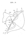
- a doctor 10 for regulating a coating 5 continuously applied to a surface of an upper roller 3 by a feeder 4 for applying the coating 5 to the surface of the upper roller 4 as a coating layer 7 at a constant thickness has a sharp knife edge portion 10a with a flank or escape surface 10b and a facing surface 10c.
- the facing surface 10c of the edge portion 10a is confronted with the surface of upper roller 3, and is extended toward the upper roller 3 along the circumference of the upper roller 3.
- the flank surface 10b is placed in the opposite side to the facing surface 10c.
- the facing surface 10c confronted with the surface of the upper roller 3 forms an angle ⁇ 1 of approximately 60 degree with the flank surface 10b.
- an "escape angle" of ⁇ 2 formed by the flank surface 10b with the surface of the upper roller 3, i.e., an angle defined between a tangential plane 13 with which the upper roller 3 is contacted and an extension plane 11 of the flank surface 10b at an intersection 12 defined between the extension plane 11 and the upper roller surface is an obtuse angle at about 120 degrees.
- the coating 5 may include a hot melt adhesive or the like.
- the substrate 2 may include a disc-like member made of transparent resinous material.
- the hot melt adhesive is applied to one surface of the substrate. Thereafter, the substrate having the adhesive is bonded with one having the same shape (not shown). These steps are suitable for producing an optical video disc.
- the roll coater according to the present invention is suitable for applying onto disc substrates a hot melt adhesive as a protective layer or a bonding adhesive for the optical disc as shown in, for example, the Japanese Patent Unexamined Publication No. Sho. 58-6536.
- the coating supplied from the feeder is formed into a coating layer at a uniform thickness, because the escape angle formed by the contact portion of the doctor 10 relative to the upper roller 3 is an obtuse angle, so that the coating supplied from the feeder will not escape to the flank surface side of the doctor. As a result, all the coating is coated on the surface of the roller. Therefore, the coating is prevented from dropping onto the surface of the substrate.
Landscapes
- Coating Apparatus (AREA)
Applications Claiming Priority (2)
| Application Number | Priority Date | Filing Date | Title |
|---|---|---|---|
| JP12447989U JPH0361959U (de) | 1989-10-24 | 1989-10-24 | |
| JP124479/89 | 1989-10-24 |
Publications (3)
| Publication Number | Publication Date |
|---|---|
| EP0425067A2 true EP0425067A2 (de) | 1991-05-02 |
| EP0425067A3 EP0425067A3 (en) | 1991-10-30 |
| EP0425067B1 EP0425067B1 (de) | 1993-10-20 |
Family
ID=14886540
Family Applications (1)
| Application Number | Title | Priority Date | Filing Date |
|---|---|---|---|
| EP90304154A Expired - Lifetime EP0425067B1 (de) | 1989-10-24 | 1990-04-18 | Vorrichtung zum Auftragen eines Beschichtungsmittels auf einer Substratoberfläche |
Country Status (3)
| Country | Link |
|---|---|
| EP (1) | EP0425067B1 (de) |
| JP (1) | JPH0361959U (de) |
| DE (1) | DE69004048T2 (de) |
Cited By (1)
| Publication number | Priority date | Publication date | Assignee | Title |
|---|---|---|---|---|
| GB2533313A (en) * | 2014-12-15 | 2016-06-22 | Airbus Operations Ltd | Flowable material applicator |
Family Cites Families (6)
| Publication number | Priority date | Publication date | Assignee | Title |
|---|---|---|---|---|
| JPS6049963B2 (ja) * | 1977-08-22 | 1985-11-06 | 三菱電機株式会社 | 信号記録装置 |
| JPS586536A (ja) * | 1981-07-01 | 1983-01-14 | Pioneer Electronic Corp | 光学式デイスク |
| JPS6039370U (ja) * | 1983-08-23 | 1985-03-19 | パイオニア株式会社 | ロ−ルコ−タ |
| DE8415154U1 (de) * | 1984-05-18 | 1984-09-13 | Jagenberg AG, 4000 Düsseldorf | Vorrichtung zum beschichten laufender materialbahnen |
| JPS6242759A (ja) * | 1985-08-19 | 1987-02-24 | Hirano Kinzoku Kk | 被膜塗工装置 |
| JPH03501823A (ja) * | 1987-10-10 | 1991-04-25 | ツインマー,ヨハネス | 塗着装置 |
-
1989
- 1989-10-24 JP JP12447989U patent/JPH0361959U/ja active Pending
-
1990
- 1990-04-18 EP EP90304154A patent/EP0425067B1/de not_active Expired - Lifetime
- 1990-04-18 DE DE1990604048 patent/DE69004048T2/de not_active Expired - Fee Related
Cited By (1)
| Publication number | Priority date | Publication date | Assignee | Title |
|---|---|---|---|---|
| GB2533313A (en) * | 2014-12-15 | 2016-06-22 | Airbus Operations Ltd | Flowable material applicator |
Also Published As
| Publication number | Publication date |
|---|---|
| DE69004048T2 (de) | 1994-05-05 |
| JPH0361959U (de) | 1991-06-18 |
| DE69004048D1 (de) | 1993-11-25 |
| EP0425067B1 (de) | 1993-10-20 |
| EP0425067A3 (en) | 1991-10-30 |
Similar Documents
| Publication | Publication Date | Title |
|---|---|---|
| WO1998052074A1 (fr) | Composant optique en plastique pourvu d'une pellicule empechant la reflexion et mecanisme servant a uniformiser l'epaisseur de cette pellicule | |
| US4077830A (en) | Laminate and method for protecting photographic element | |
| US5332607A (en) | Water-soluble double-faced adhesive tape for splicing | |
| AU691146B2 (en) | Method and apparatus for applying a coating material to sheets | |
| EP0278663A3 (de) | Verfahren zum Formen von Polsterstücken | |
| CA2028052A1 (en) | Repositionable pressure-sensitive adhesive tape and method of making | |
| EP0396150A3 (de) | Beschichteter Schleifkörper und Verfahren zu seiner Herstellung | |
| TW263613B (en) | Uniform film thickness deposition of sputtered materials | |
| EP0654306A4 (de) | Verfahren und vorrichtung zum flüssigkeitsauftrag. | |
| EP0855702A3 (de) | Optische Platte | |
| JPS55121092A (en) | Transcription sheet having pattern | |
| US5224995A (en) | Apparatus for applying a coating to a surface of a substrate | |
| US6482490B1 (en) | Printing sheet with base material, and method of manufacturing the same | |
| EP0425067B1 (de) | Vorrichtung zum Auftragen eines Beschichtungsmittels auf einer Substratoberfläche | |
| EP0982604A3 (de) | Herstellungsverfahren für optische Filter | |
| EP0356886A3 (de) | Verfahren zur Ausrüstung eines Polyolefinharz-Substrats mit einer Klebeschicht | |
| CA1164832A (en) | Glue applicator for a labelling machine | |
| EP0932061A3 (de) | Optische Komponenten mit dünnen magnetischen filmen zur Orientierung und Verfahren zu ihren Aufbau | |
| EP1275521A3 (de) | Klebevorrichtung für die Buchbinderei | |
| CA2067996A1 (en) | Method and Device for Coating of a Moving Base | |
| EP0814470A3 (de) | Optische Platte und Verfahren zu deren Herstellung | |
| EP0525332A1 (de) | Methode und Vorrichtung zur Endlosbeschichtung | |
| MY115161A (en) | Multiple data surface optical data storage system. | |
| US5002813A (en) | Substrate with protective film and method of manufacturing optical memory device using the same | |
| US4123567A (en) | Process for applying electrodes to the surfaces of electroacoustic transducer elements such as ceramic discs |
Legal Events
| Date | Code | Title | Description |
|---|---|---|---|
| PUAI | Public reference made under article 153(3) epc to a published international application that has entered the european phase |
Free format text: ORIGINAL CODE: 0009012 |
|
| AK | Designated contracting states |
Kind code of ref document: A2 Designated state(s): DE FR GB |
|
| PUAL | Search report despatched |
Free format text: ORIGINAL CODE: 0009013 |
|
| AK | Designated contracting states |
Kind code of ref document: A3 Designated state(s): DE FR GB |
|
| 17P | Request for examination filed |
Effective date: 19920416 |
|
| 17Q | First examination report despatched |
Effective date: 19920612 |
|
| GRAA | (expected) grant |
Free format text: ORIGINAL CODE: 0009210 |
|
| AK | Designated contracting states |
Kind code of ref document: B1 Designated state(s): DE FR GB |
|
| REF | Corresponds to: |
Ref document number: 69004048 Country of ref document: DE Date of ref document: 19931125 |
|
| ET | Fr: translation filed | ||
| PLBE | No opposition filed within time limit |
Free format text: ORIGINAL CODE: 0009261 |
|
| STAA | Information on the status of an ep patent application or granted ep patent |
Free format text: STATUS: NO OPPOSITION FILED WITHIN TIME LIMIT |
|
| 26N | No opposition filed | ||
| PGFP | Annual fee paid to national office [announced via postgrant information from national office to epo] |
Ref country code: GB Payment date: 19950410 Year of fee payment: 6 Ref country code: DE Payment date: 19950410 Year of fee payment: 6 |
|
| PGFP | Annual fee paid to national office [announced via postgrant information from national office to epo] |
Ref country code: FR Payment date: 19950411 Year of fee payment: 6 |
|
| PG25 | Lapsed in a contracting state [announced via postgrant information from national office to epo] |
Ref country code: GB Effective date: 19960418 |
|
| GBPC | Gb: european patent ceased through non-payment of renewal fee |
Effective date: 19960418 |
|
| PG25 | Lapsed in a contracting state [announced via postgrant information from national office to epo] |
Ref country code: FR Effective date: 19961227 |
|
| PG25 | Lapsed in a contracting state [announced via postgrant information from national office to epo] |
Ref country code: DE Effective date: 19970101 |
|
| REG | Reference to a national code |
Ref country code: FR Ref legal event code: ST |