EP0425174A2 - Evaluation de courbe paramétrique pour système d'affichage graphique à calculateur - Google Patents
Evaluation de courbe paramétrique pour système d'affichage graphique à calculateur Download PDFInfo
- Publication number
- EP0425174A2 EP0425174A2 EP90311369A EP90311369A EP0425174A2 EP 0425174 A2 EP0425174 A2 EP 0425174A2 EP 90311369 A EP90311369 A EP 90311369A EP 90311369 A EP90311369 A EP 90311369A EP 0425174 A2 EP0425174 A2 EP 0425174A2
- Authority
- EP
- European Patent Office
- Prior art keywords
- curve
- coordinates
- data
- successive
- points
- Prior art date
- Legal status (The legal status is an assumption and is not a legal conclusion. Google has not performed a legal analysis and makes no representation as to the accuracy of the status listed.)
- Withdrawn
Links
Images




Classifications
-
- G—PHYSICS
- G06—COMPUTING OR CALCULATING; COUNTING
- G06F—ELECTRIC DIGITAL DATA PROCESSING
- G06F17/00—Digital computing or data processing equipment or methods, specially adapted for specific functions
- G06F17/10—Complex mathematical operations
- G06F17/17—Function evaluation by approximation methods, e.g. inter- or extrapolation, smoothing, least mean square method
Definitions
- This invention relates to apparatus and method for evaluating and rendering parametric curves for a computer graphics display system.
- U.S. Patent 4,760,548 describes a method and apparatus of providing a visual representation of a curve wherein curve data is provided by a b-spline equation computed with a forward difference technique using scaled integer variables.
- this approach suffers from a number of drawbacks. It supports only uniform non-rational b-splines, a subset of the broader class of non-uniform rational b-splines (NURBS) and cannot effectively render certain curves such as circles.
- NURBS non-uniform rational b-splines
- This earlier approach operates on individual spans of a curve in isolation from neighboring spans and depends on integer arithmetic to avoid accumulation of errors obtained when using floating point arithmetic for the forward difference algorithm. There are significant penalties in terms of efficiency, speed and utility associated with these limitations.
- U.S. Patent 4,855,935 describes a "Method and Apparatus For Rendering Vectors Using Bresenham Parameters."
- This approach like the one in U.S. Patent 4,760,548 does not support NURBS, is strongly dependent on the forward difference algorithm, operates on individual spans in isolation from neighboring spans, depends on integer arithmetic, seems specific to the cubic form and, further, converts a curve directly to single pixels.
- a method of converting NURBS data representative of a parametric curve into geometric coordinates of vertices of a polyline for subsequent rendering on the screen of a computer graphics display system, said curve being composed of successive spans comprising the steps of: organising and locating the NURBS data in memory as a sequence of data records, a first subset of said sequence defining a first span of the curve and each successive individual data record of the sequence, in conjunction with prior data records, defining a corresponding successive span of the curve; reading said first subset of data records in said sequence and employing said subset to evaluate the coordinates of determined parameter points along the first span of the curve; and reading each successive individual data record of the sequence and evaluating the coordinates of determined parameter points along the corresponding successive span therewith.
- the graphics control processor also transforms control points associated with the parametric curve from modeling coordinates to view coordinates, converts the transformed control point coordinates to homogeneous coordinates, determines a parametric coordinate interval for tessellating the parametric curve, and generates a series of interval spaced parameter points to be used in the evaluation.
- the parallel floating point processors implement a Cox-DeBoor process in performing evaluation.
- One of the parallel processors provides a weight output for each parameter point evaluated and the further floating point processor calculates the reciprocal of the weight and multiplies the reciprocal by the outputs of the three remaining parallel processors to obtain the geometric coordinates.
- a clipping processor and frame buffer can advantageously be arranged in series with the output of the further floating point processor and operate in pipeline fashion therewith.
- the NURBS data is arranged in the following sequence to allow sharing of such data by successive spans of a complex curve: a first sequence portion specifying the order k and number of control points n of the curve; a second sequence portion comprising knot values for the first through the k-1 knots of the curve; a third sequence portion comprising k-1 successive sets of data, each set comprising coordinates and an associated weight w for a control point and a knot value, the data sets including data for the first through k-1 control points and k through 2k-2 knots of the curve; a fourth sequence portion comprising n-k additional successive sets of data, these data sets including data for the k through n control points and 2k-1 through n+k-1 knots of the curve, and tesselation parameters 1 through n-k+1; and a fifth sequence portion comprising a n+k knot value.
- the invention also provides a method of evaluating and rendering a parametric curve of order k upon a screen of a computer graphics display system, the curve being represented by NURBS data and composed of successive spans, each span being defined by k control points and 2k-2 knot values, comprising the steps of: organising and locating the NURBS data including modelling coordinates of control points and associated weights and knot values in a memory as a sequence of data records such that successive spans of the parametric curve are defined by individual successive data records in conjunction with the immediately preceding 2k-3 prior data records of the sequence; reading the data records from memory in said sequence; transforming the control point modelling coordinates to view coordinates; multiplying the transformed coordinates of a control point by its associated weight to produce a set of homogenous coordinates wx, wy, wz, w for each control point; calculating a parametric coordinate interval and generating therefrom a series of parameter points, successive parameter points being spaced apart by said interval; with parallel floating point processors simultaneously evaluating the b splin
- An apparatus and method for evaluating and rendering parametric curves based on NURBS offers many advantages including high performance, good numerical stability, cost effectiveness, high speed and accuracy, greater control over the curves, compatibility with the proposed PHIGS PLUS standard, and the elimination of data redundancy. Further, a computer graphics display system can be allowed to fully capitalize on the inherent characteristics and advantages of NURBS, including such features as the ability to construct complex curves using low order NURBS, local control, the convex hull property, the ability to render conic sections accurately using weights, invariance with respect to coordinate transformations and significant data compression.
- NURBS non-uniform rational b-splines
- Parametric curves may also be defined in terms of simple polynomials, and any such parametric polynomial function may be represented exactly by a corresponding NURBS function.
- NURBS curves may be defined in either rational or non-rational forms.
- each component (x,y,z) of a NURBS curve may be determined by evaluating a polynomial function of the parametric coordinate:
- W(t) ⁇ c wi t i .
- Each NURBS function may be characterized by the degree (m) corresponding to the highest power of the parametric coordinate, and the order (k), which equals m + 1 corresponding to the number of linearly independent terms in a polynomial of degree m.
- a quadratic function, ax2 + bx + c has a degree 2 and order 3.
- a NURBS function may be represented by multiple sets of coefficients, each of which is valid only for a limited range of the parametric coordinate.
- a curve may be divided into a sequence of successive spans, each represented by different polynomials. This is illustrated by the 2 dimensional curve C in Fig. 1, which consists of three spans. The first span is defined by parameter values t running from t0 to t1, and the coordinates of this portion of the curve are determined by the polynomials:
- the second span is defined by parametric values t running from t1 to t2, and the coordinates of this portion of the curve are determined by the polynomials
- NURBS are determined by control points, weights, and knot vectors.
- the control points provide the primary control over the geometry of a curve.
- a curve may have n control points, where n must be greater than or equal to the order (k) of the curve.
- Each span of a curve has k control points.
- the control points determine the general shape of the curve, but the curve usually does not pass through these points.
- Figure 2 illustrates a curve C with 6 control points labelled 1-6.
- weight values are only used to define the rational form of the NURBS curves.
- a weight (w) is associated with each of the coordinates (x,y,z) of the control points.
- the weights and coordinates are combined to form the homogeneous coordinates (wx,wy,wz,w), which define the control points for a set of four parametric polynomial functions, WX(t), WY(t), WZ(t), and W(t).
- the weights are required to be positive and greater than zero.
- the values of the weights are usually close to unity, and the rational form reduces to the non-rational form if the weights are all equal.
- the knot vectors for a curve define a partitioning of the parameter space for the parametric coordinate (t).
- the knot vector for a curve of order k with n control points will have n + k components, of which the first and last are never used.
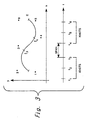
- These knot values are divided into two groups: one having m knot values preceding the span and the other having m knot values following the span. For an illustration, see Figure 3 in which a span (t3 - t4) of curve C has 3 knot values (t1, t2, t3) preceding the span and 3 knot values (t4, t5, t6) following the span.
- the knot values will determine if the b-spline is uniform or non-uniform. If the values of the knots are spaced uniformly (for example, 0, 1, 2, 3), then the result is a uniform b-spline. For a non-uniform b-spline, the knot values may be separated by irregular intervals, and knot values may be repeated, as in the knot vector (0.0, 1.2, 1.5, 1.5, 2.7, 9.0).
- NURBS is used generically and is meant to encompass the special cases of non-rational (weights set equal to 1) and uniform b-splines.
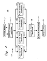
- a curve evaluation and rendering system constructed in accordance with the principles of the present invention, is represented in Figure 4, and includes the following principal components:
- the system memory (12) contains the NURBS data for each parametric curve.
- the data is stored in memory 12 and is transmitted to the graphics control processor (14) in a structured arrangement or sequence that permits the sharing of data by successive spans, thereby eliminating data redundancy.
- prefatory header information is located in system memory.
- the header information includes: the order (k), where k is an integer from 2 to kmax, where kmax is the maximum order supported by the floating point processors; number of control points (n), which must be ⁇ k; curve type flag, which may be 1 for non-rational, 0 for rational; curve status flag, which may be 0 for tessellation parameters undefined, 1 for tessellation parameters defined; tmin and tmax, which specify the range of the parametric coordinate. Tessellation parameters will be explained subsequently.
- the values of initial knots 1 through k-1 of the curve are located in system memory.
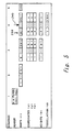
- each vertical column in Fig. 5 comprises an individual data set or record.
- Sequence portion 4 contains similar successive data sets or records, each augmented by tessellation parameter (d). Each successive data record of sequence portion 4 will complete a successive span of the curve.
- a span is defined by k control points and 2k-2 knots. Knot 1, in sequence portion 2, is not used for curve evaluation.
- the second span is completed by the second set or column of data of sequence 4 along with the prior 2k-3 columns of data (i.e.
- the final knot value n+k is located in system memory. However, this knot is not used in the curve evaluation process.
- the graphics control processor (14) reads the data stored in system memory (12), in the sequence previously explained, and can write data back to system memory, as indicated by the two-way arrows shown in Fig. 4.
- the graphics control processor transforms control point data from modeling coordinates to view coordinates, converts the transformed control point data to homogeneous coordinates (wx, wy, wz, w), determines a parametric coordinate interval (dt) for tessellating the parametric coordinate, generating a series of interval spaced parameter points (PC), and also transmits commands and data to the four parallel floating point processors (16), as more fully explained hereinafter.
- Processors 16x, 16y, 16z and 16w independently, simultaneously and synchronously evaluate the b-spline functions of a respective one of the homogeneous coordinates wx, wy, wz and w for each parameter point PC.
- the outputs wx(t), wy(t), wz(t) and w(t) from processors 16x, 16y, 16z and 16w, respectively, are provided in series to floating point processor 18.
- Processor 18 calculates the reciprocal of w(t) and multiplies wx(t), wy(t) and wz(t) by this reciprocal to determine the corresponding geometric coordinates x, y, z of vertices of the polyline representative of the curve.
- the polyline coordinates are processed in known fashion by clipping processor 20 (i.e. vectors defined by each sequential pair of vertices are clipped to the current viewing window) and sent to frame buffer 22 for rendering of the curve upon a monitor screen (not shown) of the computer graphics display, in conventional fashion.
- clipping processor 20 i.e. vectors defined by each sequential pair of vertices are clipped to the current viewing window
- frame buffer 22 for rendering of the curve upon a monitor screen (not shown) of the computer graphics display, in conventional fashion.
- System memory 12 can comprise 2 to 4 Mbytes (or more) of random access memory (RAM).
- the system memory must be capable of holding the data for at least one parametric curve and typically contains a display list composed of various graphics elements, i.e. primitives and attributes, including NURBS curves.
- Graphics control processor 14 includes: a floating point multiplier; a floating point adder, also used as an accumulator for the multiplier; a sequencer; ability to access at least 32k code memory; ability to access at least 32k data memory; 32 integer registers; and 32 registers for floating point operation.
- Processor 14 can be advantageously embodied by a 10 Mhz Weitek chip set (a XL-8136 programmable sequencer, a XL-3132 floating point processor unit, and KL-8137 integer processing unit, working together) available from Weitek of Sunnyvale, California.
- a 10 Mhz Weitek chip set (a XL-8136 programmable sequencer, a XL-3132 floating point processor unit, and KL-8137 integer processing unit, working together) available from Weitek of Sunnyvale, California.
- Floating point processors 16x, 16y, 16z, 16w and 18 can each be a VLSI processor with 32-bit floating point capability. Each of these processors includes a floating point multiplier; a floating point adder, also used as an accumulator for the multiplier; a simple sequencer; RAM for microcode; FIFO for input and output for interface; and sixty-four registers for storing data. Floating point processors are known generally in the art. Commonly assigned U.S. patent application serial number 331,021, filed March 28, 1989, discloses an invention which provides special input and output FIFOs for advantageous parallel and/or pipelined interconnection in the manner herein described, and is hereby incorporated herein by reference. Clipping processor 20 and frame buffer 22 may each contain multiple similar processors in any number and configuration which provides adequate performance.
- control points are transformed by the graphics control processor 14.
- the resulting transformed control points are converted to homogeneous coordinates (wx, wy, wz, w) and sent to the pipelined parallel processors 16 where individual coordinates are retained by respective processors 16x, 16y, 16z and 16w.
- the graphics control processor 14 determines how to tessellate the parametric coordinate (t) and sends a series of parameter values PC to the pipeline.
- Processors 16 simultaneously evaluate the wx, wy, wz, and w components in parallel for each of these values of the parametric coordinate.
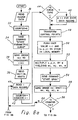
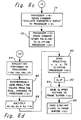
- the header information which includes the order (k), number of control points (n), curve type flag, curve status flag, tmin and tmax, is read from system memory (operation 30) and stored in registers within the graphics control processor 14.
- a register, called counter, will be used to keep track of the number of control points processed, and will initially be set to zero (operation 32).
- the graphics control processor will send the command "Start Parametric Curve” (operation 34) and the order (k) (operation 36) to each of the parallel floating point processors (16).
- the graphics control processor will read from system memory k-1 initial knots (operation 38) and will transmit these values to all of the parallel floating point processors (16).
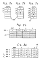
- a stack 39 within each of the parallel floating point processors will hold the knot values transmitted to said processors.
- Each stack 39 will be large enough to hold 2k-2 rows of data, and it will operate in a first in-first out (FIFO) manner.
- a data record containing a knot value (t(k)), a control point (x(1), y(1), z(1)), a weight (w(1)), and tessellation data, if available, will be read from system memory (operation 40).
- the counter will be updated by 1 (operation 42), and if the curve type is equal to 1 (inquiry 44), then the weight for each data record will be set to 1 (operation 46), which indicates a non-rational b-spline.
- the graphics control processor will transform the control point, which was just received from system memory, from modelling coordinates to view coordinates (x,y,z) (operation 48).
- a transformation matrix previously loaded in the graphics control processor, will allow x,y,z to be translated, rotated and scaled as desired, in conventional manner.
- the graphics control processor will push the knot value (t), and control point coordinates (x,y,z) onto a stack 49 in local memory of the graphics control processor (operation 50).
- This stack 49 will be large enough to hold k rows of control point data, which is sufficient for one span, and will also operate on a FIFO basis.
- control point coordinates (x,y,z) just read from system memory will be multiplied by a weight (w) yielding the weighted coordinates (wx,wy,wz,w) (operation 52).
- the graphics control processor will send the command "Start Span" (operation 54) to each of the parallel floating point processors (16).
- This command will be followed by the order (k), a knot value (t (k)), which will be pushed onto the knot stack 39 in each of the parallel floating point processors (see Figure 7b for an illustration of how the knot stack will look after this value is pushed on), and the weighted coordinates (wx,wy,wz, and w) (operation 56).
- Each component of the coordinate set (wx,wy,wz,w) will be transmitted to only one floating point processor. Therefore, wx will be sent to the first parallel floating point processor (16x), wy will be sent to the second parallel floating point processor (16y), and so forth.
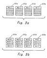
- a stack 57 is used to hold the individual component of the coordinate set (wx,wy,wz,w). Each stack can hold up to k rows of data and operates in a FIFO manner.
- Figure 9a is an illustration of individual stacks 57x, 57y, 57z and 57w within the respective parallel floating point processors 16, with the respective initial weighted coordinate pushed therein.
- knot stack 39 within each of the parallel floating point processors 16 will have data for knots 2 through 2k-1, as represented in Figure 7c;
- a span is valid if: T1 ⁇ Tmax T2 > Tmin and T2 > T1 where T1 is equal to the first knot value and T2 is equal to the second knot value on the stack 49 in the graphics control processor 14.
- the flow will once again return to operation 40 (read 1 data record) via line 64. If the span is valid and the curve status flag is 0 (operation 65), then the tessellation parameter (d) will be calculated by graphics control processor 14 (operation 66) and that value will be saved in system memory (operation 68). If the curve status flag is not equal to 0, then the flow will skip to 70 (calculate dt) via line 67, which signifies that the tessellation parameter has already been calculated.
- Tessellation is the process by which a curved line is divided into segments, which may be approximated with straight lines.
- the calculation of the tessellation parameter is dependent on the number of points in a span, which is defined by the order of the curve.
- a curve of order k has k control points per span and k-1 sections.
- dt (T2 - T1)/NStep where Nstep is determined by:
- T1 and T2 will be adjusted to fit within the boundaries of T min - and T max as follows: If T min - is between T1 and T2, then set T1 equal to T min , and if T max is between T1 and T2, then set T2 equal to T max (operation 71). Then, the graphics control processor will send the command "Evaluate Parametric Curve” to the parallel floating point processors 16 (operation 72). When the parallel floating point processors receive this command, they in turn send the command "Evaluate Parametric Curve” to the floating point processor 18 (operation 74) which then sends the command "Start Polyline” to the clipping processor (20) (operation 76). This is illustrated in Figure 6c.
- the graphics control processor sends the order (k) to the parallel floating point processors 16 (operation 78). Then, a parameter point (PC) will be initialized to T1, which is the first knot value of a span (operation 80), and PC will be sent to each of the parallel floating point processors (operation 82).
- each processor will begin evaluating the b-spline functions for one component of the control point coordinate set (wx,wy,wz,w) (operation 84). For example, the first parallel floating point processor 16x will evaluate the x coordinate of the parameter point, the second parallel floating point processor 16y will evaluate the y coordinate, and so forth. All four of the parallel floating point processors 16 evaluate their respective coordinates simultaneously.
- a process known in the art as the Cox-DeBoor (or Decasteljau) process is employed for evaluation. This process performs a linear interpolation between the components of the control points. A total of k (k-1)/2 interpolations will be performed for each value of PC sent to the floating point processor for each coordinate.
- the six knot values, t1 - t6 represent the knot values on the stack 39 in each of the floating point processors (for an illustration of this stack, see Figure 7c).
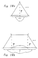
- Figure 11b is an illustration of the positioning of the before knots (t1, t2, t3), which represent the beginning of each piece to be interpolated
- Figure 11c is an illustration of the positioning of the after knots (t4, t5, t6), which represent the end of each piece to be interpolated. Therefore, an interpolation will be performed between t1 and t4, t2 and t5, and t3 and t6.
- the Cox-DeBoor evaluation process uses the above-mentioned variables in the following equations.
- f1 ((t4 - PC)x1 + (PC-t1)x2)/(t4 - t1)
- f2 ((t5 - PC)x2 + (PC-t2)x3)/(t5 - t2)
- f3 ((t6 - PC)x3 + (PC-t3)x4)/(t6 - t3)
- the second stage of interpolation requires a repositioning of the knot values. At this stage, we only have 3 points, therefore we only require knots t2 through t5. Knots t2 and t3 are the new before knots and t4 and t5 are the new after knots.
- the parallel floating point processors 16 will send the resulting coordinate values (wx(t), wy(t), wz(t), w(t)) to floating point processor 18 in a synchronized manner such that these coordinate values are received in series (operation 86).
- this processor 18 Upon receiving each set of coordinate values, this processor 18 will compute 1/w(t) and multiply this by (wx(t), wy(t), wz(t), w(t)) (operation 88) to obtain the geometric coordinates (x,y,z). These coordinates are then sent to the clipping processor 20 (operation 90).
- the clipping processor receives the coordinates sent by the processor 18, and clips the vectors defined by each sequential pair of coordinates to the current viewing boundaries (operation 92). These resulting sets of clipped vectors are sent to the frame buffer 22 (operation 94) where they are drawn as straight line segments (96).
- the counter is examined to see if it is less than the number of control points (operation 106). If it is, then the flow returns to operation 40 (read 1 data record) via line 108, and the whole process is repeated until it is completed n times.
- the graphics control processor 14 sends the command "End of Curve” (operation 110) to the parallel floating point processors 16.
- NURBS non-uniform rational b-splines
- NURBS because of their inherent characteristics provide many advantages, and the present invention fully utilizes those advantages.
- NURBS allow curves to be divided into sequences of spans, in which each span is represented by a different set of parametric polynomials.
- the parametric polynomials which describe adjacent spans of a NURBS curve provide a specific degree of continuity.
- the degree of continuity may be controlled so that a smooth curve or a curve with sharp corners may be drawn.
- the ability to match successive spans with a specified degree of continuity enables the construction of a complex curve passing through many points using low order NURBS. This property is extremely valuable because it makes it possible to avoid high order functions, which are usually costly to evaluate and prone to numerical instabilities.
- NURBS Another characteristic of NURBS is local control. Since NURBS are determined by control points, weights and knot vectors, it is possible to alter a span of the curve by moving a control point without affecting the whole of the curve.
- the convex hull property offers further advantages. NURBS curves are contained within the convex hull of their control points.
- the convex hull is the smallest convex polygon (for a 2-dimensional case) or the smallest convex polyhedron (for a 3-dimensional case) which contains a given set of points.
- Each span of a curve must lie within the convex hull of the k control points which determine that span. This characteristic makes it possible to make estimates of and place bounds on the size and location of a NURBS curve without evaluating any points. This is particularly important in trivial rejection testing. In other words, if the convex hull does not overlap with the current screen, then the curve is not evaluated and it is rejected. If the curve is not rejected, then the convex hull may be used to determine the points at which the curve is evaluated.
- the weights associated with the control points provide exact representations of conic sections, which include circles and ellipses. This is a particularly important advantage since many objects require circular forms.
- a further advantage is that transformations are accomplished using control points rather than vertices. Since there are usually fewer control points than vertices, this method is more economical.
- the evaluation technique employed herein uses the control points directly which results in reduced set-up cost.
- the interpolation formulas preserve the numerical stability of the NURBS functions, and each point is computed independently, so there are no cumulative errors as the calculations progress across a span. Consequently the last point on a curve will be just as accurate as the first, and each span will match the next with maximum accuracy.
- NURBS curves form very compact data structures resulting in significantly improved data transfer rates, better use of system resources and the ability to support more complex graphics, as compared to the traditional polyline data. These advantages are preserved by processing the NURBS data in its original form and enhanced by the approach of span sharing data sequencing.
- a curve evaluation system which organizes and locates in memory, NURBS data representative of a multispan parametric curve of order k, as a sequence of data records.
- the data records in the sequence are arranged such that successive spans of the curve are defined by successive individual records in conjunction with a plurality of immediately preceding prior data records of the sequence.
- Data records are read in sequence by a graphics control processor, which selectively passes the NURBS data and commands to a pipelined arrangement of floating point processors.
- the pipelined arrangement includes four parallel processors having their outputs connected to the input of a further processor.
- the parallel processors serve to simultaneously evaluate the b-spline functions for individual components of a set of homogeneous coordinates (wx, wy, wz, w) at determined parameter points along the curve.
- the further floating point processor converts the homogeneous coordinates to geometric coordinates for subsequent rendering of the curve on a screen of the graphics display system.
- the apparatus and method for evaluating and rendering parametric curves based on NURBS, disclosed herein, have many advantages, which include high performance, good numerical stability, cost effectiveness, high speed and accuracy, greater control over the curves, compatibility with the proposed PHIGS PLUS standard for interactive 3-D graphics, and the elimination of data redundancy.
Landscapes
- Physics & Mathematics (AREA)
- Engineering & Computer Science (AREA)
- General Physics & Mathematics (AREA)
- Mathematical Analysis (AREA)
- Mathematical Optimization (AREA)
- Pure & Applied Mathematics (AREA)
- Computational Mathematics (AREA)
- Data Mining & Analysis (AREA)
- Mathematical Physics (AREA)
- Theoretical Computer Science (AREA)
- Algebra (AREA)
- Databases & Information Systems (AREA)
- Software Systems (AREA)
- General Engineering & Computer Science (AREA)
- Image Generation (AREA)
Applications Claiming Priority (2)
| Application Number | Priority Date | Filing Date | Title |
|---|---|---|---|
| US42691289A | 1989-10-24 | 1989-10-24 | |
| US426912 | 1989-10-24 |
Publications (2)
| Publication Number | Publication Date |
|---|---|
| EP0425174A2 true EP0425174A2 (fr) | 1991-05-02 |
| EP0425174A3 EP0425174A3 (en) | 1992-10-07 |
Family
ID=23692710
Family Applications (1)
| Application Number | Title | Priority Date | Filing Date |
|---|---|---|---|
| EP19900311369 Withdrawn EP0425174A3 (en) | 1989-10-24 | 1990-10-17 | Parametric curve evaluation for a computer graphics display system |
Country Status (2)
| Country | Link |
|---|---|
| EP (1) | EP0425174A3 (fr) |
| JP (1) | JPH0766451B2 (fr) |
Cited By (2)
| Publication number | Priority date | Publication date | Assignee | Title |
|---|---|---|---|---|
| WO2001069528A3 (fr) * | 2000-03-15 | 2002-03-14 | Sun Microsystems Inc | Decompression de morphage dans un systeme graphique |
| CN116880060A (zh) * | 2023-07-18 | 2023-10-13 | 常州星宇车灯股份有限公司 | 一种基于b样条的光学曲面构建方法 |
Families Citing this family (1)
| Publication number | Priority date | Publication date | Assignee | Title |
|---|---|---|---|---|
| JP5967946B2 (ja) * | 2012-01-23 | 2016-08-10 | 株式会社アドテックエンジニアリング | 露光描画装置、露光描画システム、プログラム及び露光描画方法 |
Family Cites Families (3)
| Publication number | Priority date | Publication date | Assignee | Title |
|---|---|---|---|---|
| US4760548A (en) * | 1986-06-13 | 1988-07-26 | International Business Machines Corporation | Method and apparatus for producing a curve image |
| US4999789A (en) * | 1987-02-05 | 1991-03-12 | Hewlett-Packard Co. | Method and apparatus for trimming B-spline descriptions of patches in a high performance three dimensional graphics system |
| US4912659A (en) * | 1987-10-30 | 1990-03-27 | International Business Machines Corporation | Parallel surface processing system for graphics display |
-
1990
- 1990-09-19 JP JP24767390A patent/JPH0766451B2/ja not_active Expired - Lifetime
- 1990-10-17 EP EP19900311369 patent/EP0425174A3/en not_active Withdrawn
Cited By (3)
| Publication number | Priority date | Publication date | Assignee | Title |
|---|---|---|---|---|
| WO2001069528A3 (fr) * | 2000-03-15 | 2002-03-14 | Sun Microsystems Inc | Decompression de morphage dans un systeme graphique |
| US6525725B1 (en) | 2000-03-15 | 2003-02-25 | Sun Microsystems, Inc. | Morphing decompression in a graphics system |
| CN116880060A (zh) * | 2023-07-18 | 2023-10-13 | 常州星宇车灯股份有限公司 | 一种基于b样条的光学曲面构建方法 |
Also Published As
| Publication number | Publication date |
|---|---|
| JPH03144781A (ja) | 1991-06-20 |
| JPH0766451B2 (ja) | 1995-07-19 |
| EP0425174A3 (en) | 1992-10-07 |
Similar Documents
| Publication | Publication Date | Title |
|---|---|---|
| US5317682A (en) | Parametric curve evaluation method and apparatus for a computer graphics display system | |
| US5278948A (en) | Parametric surface evaluation method and apparatus for a computer graphics display system | |
| Shani et al. | Splines as embeddings for generalized cylinders | |
| Gallagher et al. | Computer visualization: graphics techniques for engineering and scientific analysis | |
| US7564459B2 (en) | Resolution-independent curve rendering using programmable graphics hardware | |
| US6664960B2 (en) | Apparatus for processing non-planar video graphics primitives and associated method of operation | |
| US5522019A (en) | Methods and apparatus for efficiently generating isosurfaces and for displaying isosurfaces and surface contour line image data | |
| EP0240557A1 (fr) | Informatique graphique, processeur de subdivision parallele d'elements triangulaires parametriques. | |
| EP0782105B1 (fr) | Traitement de données d'image | |
| EP1097435B1 (fr) | Evaluation parametrique de surfaces dans un espace vrai de matrice de subdivision d'un carreau irregulier | |
| US5771341A (en) | Graphics apparatus and method for dividing parametric surface patches defining an object into polygons | |
| JPH07141519A (ja) | 画像処理方法及び装置 | |
| JP4526121B2 (ja) | 三角形と線分の交点計算方法とそのプログラム | |
| US8482559B2 (en) | Method and apparatus for triangle tessellation | |
| JP3556969B2 (ja) | 投影図作成方法 | |
| JP2926637B2 (ja) | ボリュームレンダリング装置及びこれに好適な方法 | |
| EP0425174A2 (fr) | Evaluation de courbe paramétrique pour système d'affichage graphique à calculateur | |
| Rossl et al. | Visualization of volume data with quadratic super splines | |
| EP0596666A1 (fr) | Traitement de données d'images | |
| JP2005514675A (ja) | N次元空間にm次の形状を生成するための方法および装置 | |
| JP3039387B2 (ja) | 3次元cadにおけるb−スプライン曲線と直線との交点算出装置 | |
| JP3254276B2 (ja) | 貼り形状算出装置 | |
| JPH1074268A (ja) | ポリゴン画像再生方法および装置 | |
| KR100647323B1 (ko) | 섭동 함수를 이용한 3차원 객체 처리 장치 및 방법 | |
| JP3071495B2 (ja) | 物体モデル編集装置 |
Legal Events
| Date | Code | Title | Description |
|---|---|---|---|
| PUAI | Public reference made under article 153(3) epc to a published international application that has entered the european phase |
Free format text: ORIGINAL CODE: 0009012 |
|
| 17P | Request for examination filed |
Effective date: 19901213 |
|
| AK | Designated contracting states |
Kind code of ref document: A2 Designated state(s): DE FR GB IT |
|
| PUAL | Search report despatched |
Free format text: ORIGINAL CODE: 0009013 |
|
| AK | Designated contracting states |
Kind code of ref document: A3 Designated state(s): DE FR GB IT |
|
| 17Q | First examination report despatched |
Effective date: 19951019 |
|
| GRAG | Despatch of communication of intention to grant |
Free format text: ORIGINAL CODE: EPIDOS AGRA |
|
| GRAH | Despatch of communication of intention to grant a patent |
Free format text: ORIGINAL CODE: EPIDOS IGRA |
|
| STAA | Information on the status of an ep patent application or granted ep patent |
Free format text: STATUS: THE APPLICATION IS DEEMED TO BE WITHDRAWN |
|
| 18D | Application deemed to be withdrawn |
Effective date: 19970522 |