EP0425208A2 - Réceptacle pour recevoir un petit article - Google Patents
Réceptacle pour recevoir un petit article Download PDFInfo
- Publication number
- EP0425208A2 EP0425208A2 EP90311521A EP90311521A EP0425208A2 EP 0425208 A2 EP0425208 A2 EP 0425208A2 EP 90311521 A EP90311521 A EP 90311521A EP 90311521 A EP90311521 A EP 90311521A EP 0425208 A2 EP0425208 A2 EP 0425208A2
- Authority
- EP
- European Patent Office
- Prior art keywords
- cover
- projection
- hook
- fitting
- hole
- Prior art date
- Legal status (The legal status is an assumption and is not a legal conclusion. Google has not performed a legal analysis and makes no representation as to the accuracy of the status listed.)
- Withdrawn
Links
- 229920003023 plastic Polymers 0.000 claims abstract description 5
- 239000004033 plastic Substances 0.000 claims abstract description 5
- 230000037431 insertion Effects 0.000 claims description 12
- 238000003780 insertion Methods 0.000 claims description 12
- 238000001746 injection moulding Methods 0.000 claims description 4
- 238000005452 bending Methods 0.000 claims description 3
- 230000003578 releasing effect Effects 0.000 abstract description 6
- 238000002347 injection Methods 0.000 abstract 1
- 239000007924 injection Substances 0.000 abstract 1
- 230000002093 peripheral effect Effects 0.000 description 7
- 239000000463 material Substances 0.000 description 2
- 230000002265 prevention Effects 0.000 description 1
- 108010085990 projectin Proteins 0.000 description 1
- 238000000638 solvent extraction Methods 0.000 description 1
Images


Classifications
-
- A—HUMAN NECESSITIES
- A45—HAND OR TRAVELLING ARTICLES
- A45C—PURSES; LUGGAGE; HAND CARRIED BAGS
- A45C13/00—Details; Accessories
- A45C13/10—Arrangement of fasteners
- A45C13/1076—Arrangement of fasteners with a snap action
- A45C13/1084—Arrangement of fasteners with a snap action of the latch-and-catch type
-
- A—HUMAN NECESSITIES
- A45—HAND OR TRAVELLING ARTICLES
- A45D—HAIRDRESSING OR SHAVING EQUIPMENT; EQUIPMENT FOR COSMETICS OR COSMETIC TREATMENTS, e.g. FOR MANICURING OR PEDICURING
- A45D40/00—Casings or accessories specially adapted for storing or handling solid or pasty toiletry or cosmetic substances, e.g. shaving soaps or lipsticks
- A45D40/22—Casings characterised by a hinged cover
-
- E—FIXED CONSTRUCTIONS
- E05—LOCKS; KEYS; WINDOW OR DOOR FITTINGS; SAFES
- E05C—BOLTS OR FASTENING DEVICES FOR WINGS, SPECIALLY FOR DOORS OR WINDOWS
- E05C1/00—Fastening devices with bolts moving rectilinearly
- E05C1/08—Fastening devices with bolts moving rectilinearly with latching action
- E05C1/12—Fastening devices with bolts moving rectilinearly with latching action with operating handle or equivalent member moving otherwise than rigidly with the latch
- E05C1/14—Fastening devices with bolts moving rectilinearly with latching action with operating handle or equivalent member moving otherwise than rigidly with the latch the handle or member moving essentially towards or away from the plane of the wing or frame
- E05C1/145—Fastening devices with bolts moving rectilinearly with latching action with operating handle or equivalent member moving otherwise than rigidly with the latch the handle or member moving essentially towards or away from the plane of the wing or frame flush
Definitions
- the present invention relates to a receptacle for receiving a small article.
- a receptacle comprising a receptacle body integrally molded by injection molding, a cover fixed to said receptacle body by means of a hinge, said cover being automatically locked by latching a hook portion of said cover with an engaging projection of said receptacle body when said cover is closed and a lock and lock releasing means of the cover, e.g. a means for pushing the hook down from the outside of said hook for separating from the engaging projection when said cover is caused to open by releasing a locking state, was publicly known.
- the receptacle for receiving a small article comprising a receptacle body, a cover and a closing operation plate made of plastics each being independently and integrally formed by injection molding so as to constitute receptacle for receiving a small article by assembling said constitutional members, the receptacle body and the cover being connected to each other by pushing axial projections into axial holes , the closing operation plate being incorporated within a sliding groove mounted at the upper surface of the cover, said cover being caused to close by engaging a hook with a latching plate of the cover and said cover being caused to open by pushing the hook by means of an operative projection of the closing operation plate so as to separate from said latching plate.
- the hook(8) is guided by means of a hook guide hole(16) so as to push an operative projection(32) outwards from the inside of a fitting-in hole(15). As a result, said hook engages with the latching plate(17).
- the closing operation plate(4) is also moved proportional to the length of the movement of the operative projection(32) caused by the outwards pushing action of the operative projection (32) , but the closing operation plate(4) is controlled to a prescribed length of the movement due to the engagement of a projection(33) with a stopper(13). Therefore, the stopper forces to push out the operative projection(32) somewhat ourwards the fitting-in hole(15) against the aforementioned movement and tension generates to the closing operation plate(4) in proportion to the prevention of the movement.
- the reverse taper face(35) of the operative projection(32) abuts the taper face (10) of the hook (8).
- the operative projection(32) causes to press into the hook(8) and the hook(8) is released out of the latching plate(17) so as to open the cover(3) with one touch action. Since tension is applied to the closing operation plate(4) in some degree due to pushing out of the hook(8), the cover(3) may be released out of its locking state immediately by means of pushing down the touch plate(30) a little.
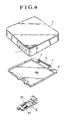
- the receptacle(1) consists of a receptacle body (2) , a cover(3) and a closing plate(4) made of plastics each molded by injection molding independently and integrally and then said each constitutional member is assembled so as to constitute the receptacle.
- the receptacle body(2) and the cover (3) are connected to each other rotationally free by fitting two axial projections(5) (5) mounted at the peripheral edge of the receptacle body (2) into axial holes(7) (7) mounted at both ends of a supporting frame(6) of said cover.
- the receptacle body(2) has the shape of a square as shown in the Figures, but it may not be limited theereto.
- the receptacle body(2) provides with a hook(8) at a peripheral edge opposing to the edge to which the cover(3) is connected.
- Said hook (8) is mounted in a raisen state from an inner peripheral surface of the receptacle body and extends upwards from the upper surface(9) of the peripheral edge and further provides with a taper face(10) facing outward from the receptacle body (2).
- (11) is a fitting-in groove of a touch plate(30).
- the cover(3) consisting of a sliding groove(12) and a stopper(12) mounted within a stopper recess(14), a fitting-in hole(15), a hook latching plate(17) and an insertion hole(18).
- the sliding groove(12) is mounted at a position corresponding to a fitting position(19) of the hook(8) by forming a raisen edge(20) at an upper surface of said cover. Further, said groove(12) is open to one end edge of the cover(3) and extends in the shape of U substantially towards the inside of said cover.
- the shape of said sliding groove may be formed in the shape of a rectagle.
- the stopper recess(14) is mounted at an upper surface of the cover(3) in the shape of a rectangular groove and further provides with the stopper(13) partitioning said groove talerally and said stopper(13) somewhat projects out of the upper surface(50) of the cover(3).
- the fitting-in hole (15) is mounted at an opening side of the sliding groove(12). As illustrated in Fig. 4 and Fig. 5, said fitting-in hole(15) is formed to have a rectangular opening portion by means of a supporting frame(22) extending in the shape of L from a lower surface of the cover(3) and , when the cover is closed onto the receptacle body(2), a lower projection(23) forming the fitting-in hole(15) has the length same as that of an external peripheral surface(24) of the receptacle body providing with the hook(8) and further an upper projection(25) is shifted somewhat inward than the lower projection(23).
- the hook guide hole(16) is mounted at said lower projection (23) and slidably guides the hook(8).
- Said hole(16) is a rectangular through hole in conform to the shape of the hook(8) and further provides with a reverse taper face(26) at one side of the inner surface of the opening.
- the hook guide hole(16) is arranged to have a position somewhat shifted from a fitting position of the hook(8) as illustrated in the Figure.
- a hook latching plate(17) is arranged at an upper end opening edge of the hook guide hole(16) which is open at the upper surface of the lower projection (23) and the hook(8) engages with said opening edge.
- An insertion inlet(18) is mounted within an insertion inlet (28) mounted at the cover(3) in a manner of contacting the risen edge(20) at the end(27) of the sliding groove(12) and opens to the lower surface of said risen edge(20) and further communicates with an hole(29) perforated at the back of the cover(3) from the lower surface of said risen edge(20).
- the closing operation plate(4) is formed in the shape of a plate substantially and further incorporated in the sliding groove.
- Said plate(4) consists of a touch plate(30), a tongue piece(31), an operative projection(32), a fitting-in groove and a projection (33).
- Said touch plate (30) is formed by bending one end of the closing operation plate (4) and has the shape fitting into the fitting-in groove of the receptacle body.
- the tongue piece(31) is mounted with a step at the end face at the side opposing to the touch plate(30) of the closing operation plate(4).
- the operative projection(32) is mounted projectively at the back of the touch plate(30) and further the fitting-in groove(34) fitting into the upper projection(25) of the cover is mounted between the back surface of the closing operation plate(4) and the operative projection(32).
- the operative projection has the width and thickness suitable for sliding within the fitting-in hole(15) of the cover(3) and further provides with the reverse taper face(35) at the front edge portion thereof.
- the projection(33) is mounted laterally within a rectangular recess(37) mounted at the back surface of the closing operation plate(4) as illustrated in Fig. 4.
- the tongue piece(31) of the closing operation plate(4) is inserted into the hole(29) within the insertion recess(28) through the insertion inlet(18).
- the tongue piece(31) is freely movable within the hole(29) and thus may easily be inserted thereinto).
- the upper projection (25) is forced to fit into the fitting-in groove(34) by utilizing the elasticity of the closing operation plate(4).
- the projection(33) engages with the stopper (13), so that the sliding action of the closing operation plate(4) is prevented, but by forcing to contact the reverse taper face(26) of the operative projection(32) with the end portion(45) of the upper projection(25), the operative projection (32) is fitted into the fitting-in hole after riding across the end portion(45) when pushed down by utilizing the elasticity of a material ; and at the same time, the upper projection(25) is fitted into the fitting-in groove(34).
- the closing operation plate (4) is incorporated in the sliding groove(12) and further the operative projection(32) is fitted fully into the fitting-in hole(15), the tongue piece(31) has space which does not abut the inner surface(38) of the hole(29) and further the stopper (13) of the cover(3) and the projection(33) of the closing plate(4) have space 0.
- the closing operation plate(4) is incorporated in the sliding groove(12) in a manner having certain space between the end surface(39) of the upper projection(25) and the inner surface(40) of the fitting-in groove (34).
- the taper face(10) of the hook(8) abuts the reverse taper. face(26) of the hook guide hole(16).
- the hook guide hole (16) is mounted at somewhat shifted position from the position of said hook ; and accordingly the taper face(10) of the hook(8) abuts at first the reverse taper face(26) of the guide hole(16) and the hook(8) slides somewhat bendingly in the direction of an arrow R in Fig. 6 while slidably guided along the hook guide hole(16).
- the taper face(10) of the hook(8) abuts the reverse taper face(35) of the operative projection(32) due to the engagement of the hook with the latching plate(17) and thus the hook(8) acts to push the operative projection(32) toward the outside of the fitting-in hole(15). That is to say,
- the closing operation plate(4) is incorporated in the cover(3) in a manner that said plate(4) may slide within the sliding groove(11) on the aforementioned condition and further the space 0 between the stopper (13) and the projection (33) and the space Q between the inner surface (43) of the touch plate(30) and the external peripheral surface(44) of the receptacle body(2) are prescribed to have the same length. It is further constituted that the operative projection(32) slides within the fitting-in hole(15) and the tongue piece(31) moves within the hole(29) on the condition that the closing operation plate slides only along the aforementioned length.
- the tongue piece(31) is at first inserted into the insertion inlet(18) and then the upper end projectin edge(25) is fitted into the fitting-in groove(34) ; at the same time the operative projection(32) is fitted into the fitting-in hole(15). It may further be possible that the upper end projection edge(25) is fitted into the fitting-in groove(34) at first and at the same time the operative projection(32) is fitted into the fitting-in hole(15). Then, the tongue piece(31) is fitted into the insertion inlet(18) so as to incorporate the closing operation plate(4) in the sliding groove(12) of the cover(3) by utilizing the elasticity of the closing operation plate(4).
- the space 0 between the stopper(13) of the cover(3) and the projection(33) of the closing operation plate(4) is prescribed to be somewhat shorter space than the moving length of the operative projection(32) toward the outside of the fitting-in hole(15). Further, the operative projection(32) is still pushed toward the outside of the fitting-in hole(15) by means of the hook(8) even when the closing operation plate(4) is prevented from the sliding movement within the sliding groove (12). The pushing forth applied to the operative projection(32) by means of the hook(8) still acts as a tensile strength for drawing the closing operation plate(4) prevented the movement thereof by means of the stopper(13) so as to generate tensile stress to the closing operation plate(4).
- the cover(3) is automatically be open by merely pushing the touch plate(30) down with the finger.
- the closing operation plate(4) slides along the sliding groove (12) and further the projection(33) moves in the direction where it separates from the engagement with the stopper(13).
- the reverse taper face(35) of the operative projection(32) acts to push the taper face(10) of the hook(8) inwards the fitting-in hole(15).
- the hook(8) separates from the latching plate(17).
- the taper face(10) of the hook(8) causes to slide the reverse taper face(35) of the operative projection(32) downward and then the hook(8) is guided within the hook guide hole(16) ; and at the same time further abuts the reverse taper face(26) of the hook guide hole(16) so as to slide downwards.
- the hook(8) also separates from the hook guide hole (16) so as to open the cover(3).
- the receptacle for receiving a small article of the present invention there is no fear of causing looseness at the connecting portion of the receptacle body and the cover or no fear of causing looseness of a locking state of the cover and furthermore a locking or lock releasing action can easily be carried out.
Landscapes
- Engineering & Computer Science (AREA)
- Mechanical Engineering (AREA)
- Connector Housings Or Holding Contact Members (AREA)
- Closures For Containers (AREA)
Applications Claiming Priority (2)
| Application Number | Priority Date | Filing Date | Title |
|---|---|---|---|
| JP124693/89U | 1989-10-25 | ||
| JP1989124693U JPH0732437Y2 (ja) | 1989-10-25 | 1989-10-25 | 容 器 |
Publications (2)
| Publication Number | Publication Date |
|---|---|
| EP0425208A2 true EP0425208A2 (fr) | 1991-05-02 |
| EP0425208A3 EP0425208A3 (en) | 1992-04-08 |
Family
ID=14891755
Family Applications (1)
| Application Number | Title | Priority Date | Filing Date |
|---|---|---|---|
| EP19900311521 Withdrawn EP0425208A3 (en) | 1989-10-25 | 1990-10-19 | A receptacle for receiving a small article |
Country Status (3)
| Country | Link |
|---|---|
| US (1) | US5131558A (fr) |
| EP (1) | EP0425208A3 (fr) |
| JP (1) | JPH0732437Y2 (fr) |
Cited By (1)
| Publication number | Priority date | Publication date | Assignee | Title |
|---|---|---|---|---|
| EP0548472A3 (fr) * | 1992-09-24 | 1993-07-21 | Wilhelm Koopmann Kg | Boítier pour cosmétiques |
Families Citing this family (19)
| Publication number | Priority date | Publication date | Assignee | Title |
|---|---|---|---|---|
| US5358135A (en) * | 1992-12-28 | 1994-10-25 | Square D Company | Access door hinge attachment |
| US5522563A (en) * | 1994-05-13 | 1996-06-04 | Eastman Kodak Company | Film cassette with latching device to prevent separation of cassette halves |
| US5755350A (en) * | 1996-06-21 | 1998-05-26 | Acco Brands, Inc. | Storage container assembly having single-finger-actuatable door latch mechanism |
| US6592000B1 (en) * | 2000-01-31 | 2003-07-15 | Paragon Medical, Inc. | Sterilization container for medical instrumentation having a sliding latch |
| US6659272B2 (en) * | 2001-07-13 | 2003-12-09 | Church Of Spiritual Technology | System for storing and transporting discs and accessory materials |
| USD475485S1 (en) | 2001-12-05 | 2003-06-03 | Wen-Cheng Sheng | Cosmetic case |
| USD517735S1 (en) * | 2004-07-01 | 2006-03-21 | Chao Ling Chemical Industry Co., Ltd. | Cosmetic casing |
| US7665625B1 (en) * | 2005-05-26 | 2010-02-23 | James L. Rothstein | Container and closure |
| DE102005036904B3 (de) * | 2005-08-05 | 2006-10-19 | A. Raymond Et Cie | Vorrichtung mit einer lösbaren Rastverbindung |
| US7556169B2 (en) * | 2005-09-15 | 2009-07-07 | Toyota Motor Manufacturing North America, Inc. | Automatic locking mechanism |
| KR100673957B1 (ko) * | 2005-12-30 | 2007-01-24 | 삼성테크윈 주식회사 | 휴대용 전자기기의 케이스 |
| US8141731B2 (en) * | 2008-05-27 | 2012-03-27 | Seaquist Closures L.L.C. | Closure with lid and slidable latch system |
| CN101752690B (zh) * | 2008-11-28 | 2012-01-04 | 鸿富锦精密工业(深圳)有限公司 | 连接器装置 |
| US8540121B2 (en) * | 2009-07-07 | 2013-09-24 | Aptargroup, Inc. | Dispensing actuator with flip-open lid |
| WO2017022068A1 (fr) * | 2015-08-04 | 2017-02-09 | 三菱電機株式会社 | Structure d'assemblage pour boîtier de dispositif électronique et dispositif électronique |
| USD882359S1 (en) * | 2017-12-22 | 2020-04-28 | Jingsheng Xu | Lunch box |
| USD874875S1 (en) * | 2018-08-08 | 2020-02-11 | Aiven On Stationery Co., Ltd. | Storage container |
| USD881653S1 (en) * | 2018-12-18 | 2020-04-21 | Can't Live Without It, LLC | Food container |
| USD927971S1 (en) * | 2019-02-08 | 2021-08-17 | Crayola Llc | Crayon container |
Family Cites Families (18)
| Publication number | Priority date | Publication date | Assignee | Title |
|---|---|---|---|---|
| FR936618A (fr) * | 1946-11-26 | 1948-07-26 | Mécanisme de fermeture pour boîtes métalliques plates pouvant servir de poudrier,d'étui à cigarettes, etc. | |
| US2633265A (en) * | 1949-03-22 | 1953-03-31 | Walter J Zipper | Powder box |
| FI31713A (fi) * | 1959-06-30 | 1961-03-10 | Doebelner Beschlaege Metall | Tuhkakuppi varsinkin moottoriajoneuvoja varten |
| FR2102896A5 (fr) * | 1970-08-28 | 1972-04-07 | Michau Georges | |
| CH530912A (de) * | 1970-10-02 | 1972-11-30 | Utz Ag Georg | Transportbehälter mit anscharniertem Deckel |
| JPS6033847Y2 (ja) * | 1981-02-06 | 1985-10-08 | 株式会社吉野工業所 | 化粧用コンパクト |
| JPS5825936Y2 (ja) * | 1981-03-16 | 1983-06-04 | 吉田工業株式会社 | コンパクト容器 |
| JPS5825937Y2 (ja) * | 1981-03-23 | 1983-06-04 | 吉田工業株式会社 | コンパクト容器 |
| JPS6018712U (ja) * | 1983-07-18 | 1985-02-08 | 釜屋化学工業株式会社 | コンパクトの開閉機構 |
| US4540090A (en) * | 1984-06-15 | 1985-09-10 | Shape, Inc. | Cassette storage container |
| FR2566373B1 (fr) * | 1984-06-25 | 1986-09-26 | Reboul Smt | Boitier a couvercle pivotant |
| US4917131A (en) * | 1985-05-06 | 1990-04-17 | Contreras Sr Joseph P | Latch assembly and front release mechanism for compacts and other containers |
| FR2595663B1 (fr) * | 1986-03-11 | 1988-06-10 | Oreal | Boitier notamment boitier de maquillage, comportant un dispositif de fermeture de structure et de manipulation simplifiees |
| US4693392A (en) * | 1986-09-15 | 1987-09-15 | Contreras Sr Joseph P | Hinge, and boss assembly for closure members |
| US4746013A (en) * | 1986-09-16 | 1988-05-24 | Sony Corporation | Disc cartridge with releasable locking means |
| US4799604A (en) * | 1987-08-05 | 1989-01-24 | Yoshida Industry Co., Ltd. | Vanity case |
| JPH0637995Y2 (ja) * | 1988-02-19 | 1994-10-05 | 日立マクセル株式会社 | テープカートリッジの収納箱 |
| FR2627458B1 (fr) * | 1988-02-24 | 1990-07-20 | Oreal | Boitiers, comprenant une base et un couvercle relies l'un a l'autre par une articulation munis d'un dispositif de fermeture comportant au moins un element mobile cooperant avec des elements fixes du couvercle et du boitier |
-
1989
- 1989-10-25 JP JP1989124693U patent/JPH0732437Y2/ja not_active Expired - Lifetime
-
1990
- 1990-10-19 EP EP19900311521 patent/EP0425208A3/en not_active Withdrawn
- 1990-10-22 US US07/602,216 patent/US5131558A/en not_active Expired - Fee Related
Cited By (1)
| Publication number | Priority date | Publication date | Assignee | Title |
|---|---|---|---|---|
| EP0548472A3 (fr) * | 1992-09-24 | 1993-07-21 | Wilhelm Koopmann Kg | Boítier pour cosmétiques |
Also Published As
| Publication number | Publication date |
|---|---|
| EP0425208A3 (en) | 1992-04-08 |
| US5131558A (en) | 1992-07-21 |
| JPH0364237U (fr) | 1991-06-24 |
| JPH0732437Y2 (ja) | 1995-07-26 |
Similar Documents
| Publication | Publication Date | Title |
|---|---|---|
| EP0425208A2 (fr) | Réceptacle pour recevoir un petit article | |
| US4331168A (en) | Vanity case | |
| US4387730A (en) | Vanity case | |
| EP0413805B1 (fr) | Logement pour pile | |
| US4831694A (en) | Buckle having external finger grip | |
| EP1596030B1 (fr) | Système de verrouillage-déverrouillage par pression résistant à la déformation | |
| US6142333A (en) | Bi-directional lid opening apparatus | |
| US4799503A (en) | Compact cosmetic case | |
| US4545097A (en) | Lock for a safety belt | |
| US5147099A (en) | Drawer or cabinet latch | |
| KR100661693B1 (ko) | 좌석 벨트 버클 | |
| US4474196A (en) | Vanity case | |
| US4542563A (en) | End release buckle | |
| JPS6345201B2 (fr) | ||
| US4886946A (en) | Slide switch with an extendible actuator | |
| US5901420A (en) | Auto-lock slide fastener slider | |
| US4943124A (en) | Ashtray for vehicles | |
| KR100257979B1 (ko) | 자동 정지장치를 갖는 슬라이드 파스너용 슬라이더 | |
| US6064577A (en) | Bottom insert belt clip mount on battery | |
| GB2320922A (en) | Disc container | |
| US4377303A (en) | Closure latch mechanism improvements | |
| GB2088335A (en) | A vanity case | |
| US6899504B2 (en) | Fastener | |
| EP0337220A2 (fr) | Récipient, notamment pour cosmétiques | |
| US4794693A (en) | Slider for a cutter knife |
Legal Events
| Date | Code | Title | Description |
|---|---|---|---|
| PUAI | Public reference made under article 153(3) epc to a published international application that has entered the european phase |
Free format text: ORIGINAL CODE: 0009012 |
|
| AK | Designated contracting states |
Kind code of ref document: A2 Designated state(s): DE FR IT |
|
| PUAL | Search report despatched |
Free format text: ORIGINAL CODE: 0009013 |
|
| AK | Designated contracting states |
Kind code of ref document: A3 Designated state(s): DE FR IT |
|
| STAA | Information on the status of an ep patent application or granted ep patent |
Free format text: STATUS: THE APPLICATION IS DEEMED TO BE WITHDRAWN |
|
| 18D | Application deemed to be withdrawn |
Effective date: 19921009 |