EP0425342A1 - Motorangetriebener Golfwagen - Google Patents
Motorangetriebener Golfwagen Download PDFInfo
- Publication number
- EP0425342A1 EP0425342A1 EP90402912A EP90402912A EP0425342A1 EP 0425342 A1 EP0425342 A1 EP 0425342A1 EP 90402912 A EP90402912 A EP 90402912A EP 90402912 A EP90402912 A EP 90402912A EP 0425342 A1 EP0425342 A1 EP 0425342A1
- Authority
- EP
- European Patent Office
- Prior art keywords
- supports
- golf cart
- female
- male
- cart according
- Prior art date
- Legal status (The legal status is an assumption and is not a legal conclusion. Google has not performed a legal analysis and makes no representation as to the accuracy of the status listed.)
- Withdrawn
Links
- 230000008878 coupling Effects 0.000 claims description 3
- 238000010168 coupling process Methods 0.000 claims description 3
- 238000005859 coupling reaction Methods 0.000 claims description 3
- 230000036961 partial effect Effects 0.000 description 4
- 239000000463 material Substances 0.000 description 3
- 230000002093 peripheral effect Effects 0.000 description 3
- 230000000903 blocking effect Effects 0.000 description 2
- 230000000670 limiting effect Effects 0.000 description 2
- 238000000926 separation method Methods 0.000 description 2
- 229910052782 aluminium Inorganic materials 0.000 description 1
- XAGFODPZIPBFFR-UHFFFAOYSA-N aluminium Chemical compound [Al] XAGFODPZIPBFFR-UHFFFAOYSA-N 0.000 description 1
- 239000000470 constituent Substances 0.000 description 1
- 230000003100 immobilizing effect Effects 0.000 description 1
- 229910052751 metal Inorganic materials 0.000 description 1
- 239000002184 metal Substances 0.000 description 1
- 238000013021 overheating Methods 0.000 description 1
- 230000000717 retained effect Effects 0.000 description 1
- 230000002441 reversible effect Effects 0.000 description 1
Images



Classifications
-
- B—PERFORMING OPERATIONS; TRANSPORTING
- B62—LAND VEHICLES FOR TRAVELLING OTHERWISE THAN ON RAILS
- B62B—HAND-PROPELLED VEHICLES, e.g. HAND CARTS OR PERAMBULATORS; SLEDGES
- B62B1/00—Hand carts having only one axis carrying one or more transport wheels; Equipment therefor
- B62B1/02—Hand carts having only one axis carrying one or more transport wheels; Equipment therefor in which the wheel axis is disposed between the load and the handles
- B62B1/04—Hand carts having only one axis carrying one or more transport wheels; Equipment therefor in which the wheel axis is disposed between the load and the handles involving parts being adjustable, collapsible, attachable, detachable, or convertible
- B62B1/042—Hand carts having only one axis carrying one or more transport wheels; Equipment therefor in which the wheel axis is disposed between the load and the handles involving parts being adjustable, collapsible, attachable, detachable, or convertible foldable
-
- B—PERFORMING OPERATIONS; TRANSPORTING
- B62—LAND VEHICLES FOR TRAVELLING OTHERWISE THAN ON RAILS
- B62B—HAND-PROPELLED VEHICLES, e.g. HAND CARTS OR PERAMBULATORS; SLEDGES
- B62B5/00—Accessories or details specially adapted for hand carts
- B62B5/0026—Propulsion aids
-
- B—PERFORMING OPERATIONS; TRANSPORTING
- B62—LAND VEHICLES FOR TRAVELLING OTHERWISE THAN ON RAILS
- B62B—HAND-PROPELLED VEHICLES, e.g. HAND CARTS OR PERAMBULATORS; SLEDGES
- B62B2202/00—Indexing codes relating to type or characteristics of transported articles
- B62B2202/40—Sport articles
- B62B2202/404—Golf articles, e.g. golfbags
-
- B—PERFORMING OPERATIONS; TRANSPORTING
- B62—LAND VEHICLES FOR TRAVELLING OTHERWISE THAN ON RAILS
- B62B—HAND-PROPELLED VEHICLES, e.g. HAND CARTS OR PERAMBULATORS; SLEDGES
- B62B5/00—Accessories or details specially adapted for hand carts
- B62B5/0026—Propulsion aids
- B62B5/0033—Electric motors
- B62B5/0036—Arrangements of motors
- B62B5/0046—One motor drives two wheels
-
- B—PERFORMING OPERATIONS; TRANSPORTING
- B62—LAND VEHICLES FOR TRAVELLING OTHERWISE THAN ON RAILS
- B62B—HAND-PROPELLED VEHICLES, e.g. HAND CARTS OR PERAMBULATORS; SLEDGES
- B62B5/00—Accessories or details specially adapted for hand carts
- B62B5/0026—Propulsion aids
- B62B5/0069—Control
-
- Y—GENERAL TAGGING OF NEW TECHNOLOGICAL DEVELOPMENTS; GENERAL TAGGING OF CROSS-SECTIONAL TECHNOLOGIES SPANNING OVER SEVERAL SECTIONS OF THE IPC; TECHNICAL SUBJECTS COVERED BY FORMER USPC CROSS-REFERENCE ART COLLECTIONS [XRACs] AND DIGESTS
- Y10—TECHNICAL SUBJECTS COVERED BY FORMER USPC
- Y10S—TECHNICAL SUBJECTS COVERED BY FORMER USPC CROSS-REFERENCE ART COLLECTIONS [XRACs] AND DIGESTS
- Y10S280/00—Land vehicles
- Y10S280/05—Motorized golf carts
-
- Y—GENERAL TAGGING OF NEW TECHNOLOGICAL DEVELOPMENTS; GENERAL TAGGING OF CROSS-SECTIONAL TECHNOLOGIES SPANNING OVER SEVERAL SECTIONS OF THE IPC; TECHNICAL SUBJECTS COVERED BY FORMER USPC CROSS-REFERENCE ART COLLECTIONS [XRACs] AND DIGESTS
- Y10—TECHNICAL SUBJECTS COVERED BY FORMER USPC
- Y10S—TECHNICAL SUBJECTS COVERED BY FORMER USPC CROSS-REFERENCE ART COLLECTIONS [XRACs] AND DIGESTS
- Y10S280/00—Land vehicles
- Y10S280/06—Wheeled golf club carriers
-
- Y—GENERAL TAGGING OF NEW TECHNOLOGICAL DEVELOPMENTS; GENERAL TAGGING OF CROSS-SECTIONAL TECHNOLOGIES SPANNING OVER SEVERAL SECTIONS OF THE IPC; TECHNICAL SUBJECTS COVERED BY FORMER USPC CROSS-REFERENCE ART COLLECTIONS [XRACs] AND DIGESTS
- Y10—TECHNICAL SUBJECTS COVERED BY FORMER USPC
- Y10T—TECHNICAL SUBJECTS COVERED BY FORMER US CLASSIFICATION
- Y10T403/00—Joints and connections
- Y10T403/32—Articulated members
- Y10T403/32254—Lockable at fixed position
- Y10T403/32262—At selected angle
- Y10T403/32319—At selected angle including pivot stud
- Y10T403/32393—At selected angle including pivot stud including bridging keeper
Definitions
- the present invention relates to a motorized golf cart, of the type comprising a chassis formed of at least two supports assembled to each other by a rotary type connecting device consisting of two male and female parts nested one in the other and respectively secured to the two supports of the chassis, one of the supports carrying two driving wheels, an electric motor and a battery, the other support essentially consisting of an operating handle terminated at one end by a handle having a manually controlled member connected to the engine by an electrical connection including an intermediate socket.
- chassis of a motorized or non-motorized golf cart is now of the foldable or dismountable type in order to significantly reduce its size and thus facilitate transport in a car trunk for example.
- an intermediate connection socket is made necessary at the level of the electrical connection between the motor carried by a first support of the chassis and its control member carried by the handle of operation which constitutes a second support of the chassis removably attached to the first support.
- This electrical connection with intermediate plug is generally a flexible electric cable passing outside the chassis.
- the object of the invention is to design a motorized golf cart with an electrical connection of a type new between the engine and its control member, this connection being more particularly suited to a chassis of the type described in document FR-2 621 251 in the name of the applicant.
- the chassis described in the aforementioned document advantageously consists of two supports assembled to one another by a rotary type connecting device comprising two male and female parts fitted one into the other and respectively integral with the two supports of the frame.
- This chassis is such that the two supports can take two positions relative to each other while remaining linked to each other.
- the two supports In a first position or position of use of the carriage, the two supports are generally 90 ° from each other (the operating handle being in a plane perpendicular to the axis of the wheels and halfway between those -ci), and in the second position or storage position, the two supports are generally coplanar (the operating handle being substantially parallel to the axis of the wheels).
- the male and female elements of the intermediate socket or connector are respectively supported by the two male female parts of the connection device, and they are aligned on the axis of rotation of the two supports of the chassis.
- the male and female elements of the auxiliary connector are fitted one into the other, which suggests that the connector ensures in both cases the electrical continuity of the link on which it is inserted.
- the motor can be rotated if the control member located on the handle is not in the stop position.
- the carriage is in the storage position, and although the male and female elements of the connector are nested one inside the other, the continuity of the connection is nevertheless interrupted at the level of the connector.
- the cylindrical connector is chosen for example with a number of contacts greater than the number necessary to ensure the continuity of the electrical connection, so that the aforementioned conditions are satisfied by an appropriate choice of the male and female contacts actually used.
- the motor is housed in a housing on which is removably fixed another housing in which the battery is housed, with an external electrical connection which ensures the connection between the battery and an electronic circuit motor speed variation, this connection connecting to the battery by a socket which is supported by the battery case and which also serves to connect the battery to an external power source in order to recharge it.
- control handle is formed by two half-arms articulated to each other around an eccentric pivot axis, and it comprises means for limiting the pivoting movement of the two half-arms between two extreme positions corresponding respectively to the folded and unfolded handle, and means for locking in position the two half-arms in the unfolded position of the handle.
- the carriage is towed or propelled according to the direction of assembly of the operating handle.
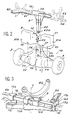
- the motorized golf cart comprises a frame 1 which essentially supports a removable bag (not shown), two-wheel drive 3, an electric motor M, an autonomous energy source such as a battery B, an operating and guiding handle 4 with a manually controlled element 60 connected by an electrical connection L to an electronic circuit 58 for varying the speed of the motor M.
- the chassis 1 is formed by two supports 1a, 1b articulated to each other by a connecting device 5 of the rotary type.
- the support 1a is formed by two half-arms 6a, 6b substantially of the same length and which constitute the operating handle of the carriage.
- each half-arm 6a, 6b consists of a metal rod of rectangular section, made of aluminum for example.
- the two half-arms 6a, 6b are articulated to each other around a pivot axis A supported by two blocks 10a, 10b respectively integral with the two half-arms 6a, 6b .
- Each block 10a, 10b advantageously made of plastic material is traversed right through by an opening 12 of rectangular section, so that it can be slidably mounted on the associated half-arm 6a, 6b.
- Each block 10a, 10b also has a hole 13 passing right through it, but along an axis perpendicular to the axis of the associated opening 12.
- Each block 10a, 10b is mounted towards one end of the associated arm 6a, 6b while being distant from this end by a length 1.
- the pivot axis A is freely housed in the two holes 13 of the two blocks 10a, 10b and is held in position by any suitable means. According to this arrangement, the axis A is off-axis with respect to the two half-arms 6a, 6b and extends perpendicularly to the latter. Considering a fixed half-arm, the other half-arm can pivot 180 ° between two extreme positions corresponding to the two folded and unfolded positions of the operating handle, respectively. To this end, each half-arm 6a, 6b supports a second block 15a, 15b advantageously made of plastic which fulfills two functions: a function of limiting the pivoting and a function of blocking in the unfolded position of the two half-arms 6a, 6b.
- Each second block 15a, 15b is traversed right through by an opening 16 of rectangular section, so that it can be slidably mounted on the associated half-arm 6a, 6b.
- Each block 15a, 15b has a housing 17 in U whose base 17a is formed by an extension of one face of the block, a first branch of which is formed by the external face of the block perpendicular to the base 17a and whose second branch 17b is formed by a parallel wall and facing said face of the block.
- the free end surface of the wall 17b has an internal rim 17c.
- Each housing 17 is substantially the dimensions of the section of each half-arm 6a, 6b.
- Each second block 15a, 15b is mounted on the associated half-arm 6a, 6b so that its housing 17 can receive the end part (adjacent to the pivot axis A) of the other half-arm.
- the half-arm 6a supports the handle 4 towards its end opposite to the pivot axis A (FIG. 1).
- This handle 4 advantageously made of plastic, has a tubular end-piece which allows it to be force-fitted at the end of the half-arm 6a.
- the manually controlled member 60 such as a rotary type potentiometer-switch.
- a plate 4a extends the handle 4 in the axis of the half-arm 6a and it is intended to support the scorecard, "tee" and balls, possibly with the presence of a small storage box.
- the half-arm 6b receives at its end opposite to the pivot axis A a tubular end piece 7 made of plastic material which forms the third support point of the carriage (the other two points being constituted by the wheels 3).
- This nozzle 7 carries a first cradle 7a on which the bag supported by straps for example (not shown) is supported.
- the half-arm 6b supports a second cradle 8a whose foot 8 is traversed right through by an opening so as to mount it sliding on the half-arm 6b on the side of its end adjacent to the axis pivot A.
- the support 1b of the chassis is a flat elongated element 15 which supports the two wheels 3 at its two ends.
- the rotary connection device 5 between the two supports 1a, 1b of the chassis is constituted as described in the aforementioned document, and it comprises two parts, respectively male 5a and female 5b, made of plastic material, nested one inside the other and respectively secured to the two supports 1a, 1b.
- the male part 5a generally in the shape of a T, has a central tubular element 20 of circular section connected, at one end, to a lateral tubular element 21 extending perpendicularly from both sides. 'other of the central tubular element 20.
- This central element 20 is extended axially, at its other end, by a tube 22 of circular section and of smaller diameter.
- the central tubular element 20 and the tube 22 define between them an annular external shoulder 24 at the surface of which project four axial bosses 25 forming a stop circumferentially regularly spaced from each other.
- the external peripheral surface of the central tubular element 20 has two grooves 26, coplanar, diametrically opposite and which extend respectively over two angular sectors of the order of 90 °.
- the external peripheral surface of the central tubular element 20 has a notch 26a separated from the groove 26 by a rib 26b.
- the male part 5a is completed by two stiffening elements 30 which extend the lateral tubular element 21 on either side of the central tubular element 20 and which are connected to the latter. These stiffening elements 30 extend over the length of the central tubular element 20 and each extend by a lug 31 which extends over part of the length of the tube 22 and which ends, radially inwards, by a pin 32.
- the two stiffening elements 30 and the legs 31 are located in a plane passing through two diametrically opposite ends of the two grooves 26 and by two diametrically opposite stops 25 of the central tubular element 20.
- the male part 5a is engaged by one end on the half-arm 6b of the operating handle by means of its lateral tubular element 21 and is then fixed in position along the half-arm 6b by means of a screw 35 for example.
- the female part 5b is constituted by a tubular element 40 in one piece with the element 15 forming the second support 1b of the chassis 1.
- This tubular element 40 is located in the center of the element 15, extends perpendicular to it. last and has a circular section with an inner diameter slightly greater than that of the tube 22 of the male part 5a, and an outer diameter substantially equal to that of the central tubular element 20 of the male part 5a.
- the tubular element 40 has four notches 41 circumferentially regularly spaced from one another.
- the external peripheral surface of the tubular element 40 has: two grooves 42, coplanar, diametrically opposite and which each extend over an angular sector of about 90 °; two notches 42a respectively towards the two ends of each groove 42, located at a different level from that of the associated groove 42 and separated from the latter by a rib 42b.
- the structure of the female part 5b is also completed by two stiffening elements 44, diametrically opposite and which each connect to the element 15 forming the second support 1b and to the tubular element 40.
- Each stiffening element 44 extends beyond from the free end surface of the tubular element 40 by a lug 45 terminated by a pin 46 extending radially inward.
- the motor M is housed in a box 50 of elongated shape consisting of two plastic half-housings joined to one another by screws for example.
- the box 50 is attached around the support 1b of the chassis 1.
- the battery B is also housed in a housing 51 formed of two plastic half-housings assembled to one another by screws for example.
- the housing 51 is divided into two compartments 51a, 51b containing battery cells and connected to each other by a central part 52 of lesser thickness.
- the housing 51 comes to rest on the housing 50 and is positioned thereon by pins 53 which respectively penetrate into two holes 54 of the housing 50.
- a locking element 55 is provided, such as a latch hook mounted on the central part 52 of the housing 51, and which cooperates with a stop 56 provided on the outer surface of the tubular element 40 of the female part 5b of the connection device 5.
- a socket 57 which is used, on the one hand, to supply the electronic circuit 58 for speed variation of the motor M by an external electric cable 59 and, on the other hand, a connection socket for recharging the elements of battery B on an external power source.
- the manually controlled element 60 of the motor M located at the handle 4 is connected by the link L such as an electric cable 61 which passes inside the half-arm 6a, partially crosses the half-arm 6b to open out inside the central tubular element 20 and its extension 22 forming the male part 5a of the connection device 5.
- the free end of the cable 61 is connected to the male element 63a of an intermediate socket or connector mounted at the end of the tube 22.
- the female element 63b of this connector is mounted at the bottom of the tubular element 40 of the female part 5b of the connection device 5.
- This female element 63b is connected by an electric cable 64 to the circuit 58, as schematically illustrated in FIG. 6.
- the intermediate connector 63a, 63b is of cylindrical shape with its male contacts and its female contacts distributed over two circles of the same diameter.
- the connector does not provide electrical continuity on the link L depending on whether the carriage is in the use position or in the storage position. This continuity is only ensured in position use of the trolley.
- a connector such that the number of male and female contacts which are necessary to ensure the continuity of the electrical connection L is less than the number of male and female contacts available, it suffices to make an appropriate choice to satisfy the aforementioned conditions. .
- the electronic circuit 58 for varying the speed of rotation of the motor M supplied from the battery B and controlled from the control member 60 located on the handle 4, determines the speed of rotation of the motor M and comprises in particular elements to ensure thermal protection against overheating of the motor M and limit the consumption of the battery.
- the motor M is coupled to a geared motor (not shown) which rotates an axle 70 on the two ends of which the two drive wheels 3 are mounted with freewheel bearings 71 known in oneself.
- a geared motor (not shown) which rotates an axle 70 on the two ends of which the two drive wheels 3 are mounted with freewheel bearings 71 known in oneself.
- Each wheel 3, removably mounted on the associated end of the axle 70, has a hubcap 3a rotatably mounted between two positions spaced a quarter of a turn away.
- Each hubcap 3a is integral with a tubular element 72 in which the associated end of the axis 70 engages, with coupling means shown diagrammatically at 73 controlled by the rotation of the hubcap 3a and which for the two positions of the hubcap 3a ensures the coupling and uncoupling between the wheel 3 and the axis 70, respectively.
- FIG. 1 Suppose the carriage as shown in Figure 1, that is to say in the storage or storage position.
- the two supports 1a, 1b of the chassis are immobilized axially and in rotation.
- the pins 32 and 46 are positioned in the notches 26a and 42a, and retained by the crossing ribs 26b and 42b to immobilize the two supports 1a and 1b axially.
- an auxiliary fixing means such as a push button whose finger 75, shown diagrammatically in FIG.
- the two supports 1a, 1b of the chassis are unlocked by bringing the pins 32 and 46 into the grooves 26 and 42, respectively, after having unlocked the locking finger 75.
- This spacing between the two supports 1a, 1b automatically causes separation male 63a and female 63b elements of the intermediate connector.
- the pins 32 and 46 are brought into abutment against the other end of the grooves 26 and 42, respectively.
- the stiffening elements 30, 45 are substantially 90 ° from each other, that is to say that the axis of the wheels 3 is in a plane perpendicular to the operating handle 6.
- the two supports 1a and 1b are immobilized by exerting an axial pressure along the axis of the connecting device 5 to again engage the pins 32 and 46 in the notches 26a and 42a, respectively, to ensure an axial immobilization, for again engage the stops 25 in the notches 41, respectively, to ensure immobilization in rotation, and to again fit one into the other the male elements 63a and female 63b of the connector.
- electrical continuity is ensured at the connector 63a, 63b, that is to say that the motor M can be controlled.
- the end of the half-arm 6a, opposite the handle 4 comes be housed inside the housing 17 of the block 15 supported by the half-arm 6b, and in a symmetrical manner, the housing 17 of the block 15 supported by the half-arm 6a receives the end of the half-arm 6b opposite to that supporting the end piece 7 forming the 3rd support point of the carriage.
- the housings 17 limit the pivoting movement of the half-arm 6a, so that the two half-arms 6a, 6b are substantially in line with one another.
- the flanges 17c of the housings 17 form a first means for retaining the two half-arms 6a and 6b in the unfolded position.
- a second retaining means is advantageously provided, such as a latch hook 80 carried by the block 15a of the half-arm 6a for immobilizing the two half-arms 6a, 6b in position (FIG. 3).
- FIGS. 7 and 7a The passage of the carriage from the storage position to the use position is schematically illustrated in FIGS. 7 and 7a.
- the motor M having only one direction of rotation, we will assume that it drives the carriage along arrow F, that is to say that the carriage is in the towed position taking into account the position of the handle operation 6.
- two half-arms P1, P2 can be defined on either side of a line passing through the axis of the wheels 3.
- the support 1a can be mounted on the support 1b with the handle 4 located either in the half-plane P1 (FIGS. 7, 7a), or in the half -plan P2 ( Figures 8, 8a).
- the position of the operating handle 6 relative to the axis of the wheels 3 conditions the towed ( Figures 7, 7a) or powered ( Figures 8, 8a) operation of the carriage.
- the constituent elements of the carriage apart from the half-arms 6a and 6b, are plastic parts molded to reduce the weight of the carriage.
- the invention is not limited to the embodiment described and given only by way of example.
- the means of axial immobilization and of rotation of the two supports of the chassis, the means of blocking of the two half-arms of the operating handle can be modified without departing from the scope of the invention.
Landscapes
- Engineering & Computer Science (AREA)
- Chemical & Material Sciences (AREA)
- Combustion & Propulsion (AREA)
- Transportation (AREA)
- Mechanical Engineering (AREA)
- Handcart (AREA)
Applications Claiming Priority (2)
| Application Number | Priority Date | Filing Date | Title |
|---|---|---|---|
| FR8913821A FR2653346B1 (fr) | 1989-10-23 | 1989-10-23 | Chariot de golf motorise. |
| FR8913821 | 1989-10-23 |
Publications (1)
| Publication Number | Publication Date |
|---|---|
| EP0425342A1 true EP0425342A1 (de) | 1991-05-02 |
Family
ID=9386649
Family Applications (1)
| Application Number | Title | Priority Date | Filing Date |
|---|---|---|---|
| EP90402912A Withdrawn EP0425342A1 (de) | 1989-10-23 | 1990-10-17 | Motorangetriebener Golfwagen |
Country Status (6)
| Country | Link |
|---|---|
| US (1) | US5109938A (de) |
| EP (1) | EP0425342A1 (de) |
| JP (1) | JPH03254767A (de) |
| AU (1) | AU635073B2 (de) |
| CA (1) | CA2028233A1 (de) |
| FR (1) | FR2653346B1 (de) |
Families Citing this family (11)
| Publication number | Priority date | Publication date | Assignee | Title |
|---|---|---|---|---|
| USD331652S (en) | 1991-03-19 | 1992-12-08 | Ching-Chang Wu | Golf cart handlebar |
| US5575413A (en) * | 1995-03-16 | 1996-11-19 | Starry; William L. | Golf bag holder apparatus |
| JP3016234U (ja) * | 1995-03-27 | 1995-09-26 | ビルコン株式会社 | 電動カート |
| USD393511S (en) | 1997-03-14 | 1998-04-14 | Albertsson Stig L | Electric golf cart |
| GB2345668A (en) * | 1999-01-12 | 2000-07-19 | Clifford Thomas Salter | Pedestrian controlled vehicle |
| US6435539B1 (en) * | 2000-11-28 | 2002-08-20 | David Wu | Folding collapsible golf cart |
| CA2447019A1 (en) * | 2003-10-27 | 2005-04-27 | Alistair Jenkins | Motorized towing apparatus |
| GB2419329B (en) * | 2004-10-25 | 2007-11-07 | David Wu | Collapsible golf cart |
| ATE390748T1 (de) * | 2005-12-16 | 2008-04-15 | Alcatel Lucent | Antriebseinheit und golfwagen |
| AU2010101306B4 (en) * | 2010-09-25 | 2011-06-23 | Motocaddy Ltd | Trolleys |
| JP7496845B2 (ja) * | 2022-02-10 | 2024-06-07 | 川上産業株式会社 | 歩行式電動運搬車 |
Citations (3)
| Publication number | Priority date | Publication date | Assignee | Title |
|---|---|---|---|---|
| FR1468148A (fr) * | 1966-02-14 | 1967-02-03 | Fabrications Unicum Soc D | Chariot automoteur à éléments démontables, destiné notamment à transporter les crosses ou clubs utilisés pour pratiquer le jeu de golf, et autres utilisations |
| US3907056A (en) * | 1974-06-13 | 1975-09-23 | Electric Golf Carts Inc | Electric golf bag carrier |
| FR2621251A1 (fr) * | 1987-10-01 | 1989-04-07 | Cad Inov Groupement Interet Ec | Chariot de golf |
Family Cites Families (5)
| Publication number | Priority date | Publication date | Assignee | Title |
|---|---|---|---|---|
| US1714698A (en) * | 1926-11-08 | 1929-05-28 | Frank M Stoll | Latch mechanism for hinge members |
| US2029484A (en) * | 1933-03-18 | 1936-02-04 | John R Howard | Fishing rod |
| US3167146A (en) * | 1963-05-08 | 1965-01-26 | Rome R Rudolph | Power driven golf cart |
| US3952821A (en) * | 1975-01-22 | 1976-04-27 | Craven Charles G | Motor driven golf bag cart |
| DE2634765A1 (de) * | 1976-08-03 | 1978-02-09 | Jakob Kirchgaesser | Zweiraedriger golfhandwagen |
-
1989
- 1989-10-23 FR FR8913821A patent/FR2653346B1/fr not_active Expired - Fee Related
-
1990
- 1990-10-16 AU AU64638/90A patent/AU635073B2/en not_active Expired - Fee Related
- 1990-10-17 EP EP90402912A patent/EP0425342A1/de not_active Withdrawn
- 1990-10-17 US US07/600,186 patent/US5109938A/en not_active Expired - Fee Related
- 1990-10-22 JP JP2284122A patent/JPH03254767A/ja active Pending
- 1990-10-22 CA CA002028233A patent/CA2028233A1/fr not_active Abandoned
Patent Citations (3)
| Publication number | Priority date | Publication date | Assignee | Title |
|---|---|---|---|---|
| FR1468148A (fr) * | 1966-02-14 | 1967-02-03 | Fabrications Unicum Soc D | Chariot automoteur à éléments démontables, destiné notamment à transporter les crosses ou clubs utilisés pour pratiquer le jeu de golf, et autres utilisations |
| US3907056A (en) * | 1974-06-13 | 1975-09-23 | Electric Golf Carts Inc | Electric golf bag carrier |
| FR2621251A1 (fr) * | 1987-10-01 | 1989-04-07 | Cad Inov Groupement Interet Ec | Chariot de golf |
Also Published As
| Publication number | Publication date |
|---|---|
| AU635073B2 (en) | 1993-03-11 |
| US5109938A (en) | 1992-05-05 |
| FR2653346B1 (fr) | 1992-02-07 |
| AU6463890A (en) | 1991-04-26 |
| CA2028233A1 (fr) | 1991-04-24 |
| JPH03254767A (ja) | 1991-11-13 |
| FR2653346A1 (fr) | 1991-04-26 |
Similar Documents
| Publication | Publication Date | Title |
|---|---|---|
| EP0939019B1 (de) | Kinderwagen | |
| FR2846570A1 (fr) | Vehicule jouet | |
| EP2174860B1 (de) | Klappbarer Roller | |
| FR2642721A1 (fr) | Vehicule personnel convertible comportant un chassis en plusieurs elements | |
| FR2741819A1 (fr) | Systeme roulant, notamment jouet roulant a changement de forme | |
| WO1991007935A1 (fr) | Fauteuil roulant demontable et sac pour le transport d'un tel fauteuil apres son demontage | |
| FR2653346A1 (fr) | Chariot de golf motorise. | |
| EP2249675A1 (de) | Verbessertes gepäckstück mit rollen | |
| EP0755841A1 (de) | Lastförderwagen | |
| FR2913396A1 (fr) | Vehicule a deux roues a encombrement variable | |
| FR3100213A1 (fr) | Vehicule electrique | |
| EP0241377B1 (de) | Ausbaubare Antriebseinheit und dazugehöriges Fahrzeug, insbesondere Golfwagen | |
| BE1010411A7 (fr) | Chariot porte tailles haies multiples a fonctionnement automtique. | |
| FR2820382A1 (fr) | Dispositif formant porte-velos pour le transport d'au moins une bicyclette transversalement a l'arriere d'un vehicule automobile | |
| FR2717139A1 (fr) | Véhicule pour le transport de matériels de golf. | |
| WO2025238313A1 (fr) | Dispositif de levage et de manutention d'un touret et de déroulage d'un matériau enroulé sur ce touret | |
| EP1762279A1 (de) | Golfausrüstung mit Handwagen und Tasche | |
| FR3098157A1 (fr) | Station de recharge d’un véhicule électrique | |
| FR3028815A1 (fr) | Remorque pour la mise a l'eau et la manutention d'embarcations legeres | |
| FR2795652A1 (fr) | Chariot pliable pour sac de golf, possedant des moyens de verrouillage perfectionnes | |
| WO2025074182A1 (fr) | Système multifonction pour paire de ski-roues | |
| FR3101604A1 (fr) | Trottinette pliable | |
| EP1479601B1 (de) | Klappfahrrad | |
| FR2539039A1 (fr) | Chariot porte-sac de golf | |
| EP4691576A1 (de) | Multifunktionssystem für ein paar von ski-rad und ski-rad-kit |
Legal Events
| Date | Code | Title | Description |
|---|---|---|---|
| PUAI | Public reference made under article 153(3) epc to a published international application that has entered the european phase |
Free format text: ORIGINAL CODE: 0009012 |
|
| AK | Designated contracting states |
Kind code of ref document: A1 Designated state(s): AT BE CH DE DK ES FR GB GR IT LI LU NL SE |
|
| 17P | Request for examination filed |
Effective date: 19911031 |
|
| 17Q | First examination report despatched |
Effective date: 19930604 |
|
| STAA | Information on the status of an ep patent application or granted ep patent |
Free format text: STATUS: THE APPLICATION IS DEEMED TO BE WITHDRAWN |
|
| 18D | Application deemed to be withdrawn |
Effective date: 19931026 |