EP0425353A1 - Rüttler und Maschine zur Traubenernte mit einem solchen RÀ¼ttler - Google Patents
Rüttler und Maschine zur Traubenernte mit einem solchen RÀ¼ttler Download PDFInfo
- Publication number
- EP0425353A1 EP0425353A1 EP90402952A EP90402952A EP0425353A1 EP 0425353 A1 EP0425353 A1 EP 0425353A1 EP 90402952 A EP90402952 A EP 90402952A EP 90402952 A EP90402952 A EP 90402952A EP 0425353 A1 EP0425353 A1 EP 0425353A1
- Authority
- EP
- European Patent Office
- Prior art keywords
- shaker
- flexible rod
- rod
- harvesting machine
- axis
- Prior art date
- Legal status (The legal status is an assumption and is not a legal conclusion. Google has not performed a legal analysis and makes no representation as to the accuracy of the status listed.)
- Granted
Links
- 238000003306 harvesting Methods 0.000 title claims abstract description 34
- 235000009754 Vitis X bourquina Nutrition 0.000 title claims description 9
- 235000012333 Vitis X labruscana Nutrition 0.000 title claims description 9
- 235000014787 Vitis vinifera Nutrition 0.000 title claims description 9
- 240000006365 Vitis vinifera Species 0.000 title 1
- 241000219095 Vitis Species 0.000 claims description 8
- 230000010355 oscillation Effects 0.000 claims description 6
- 239000011152 fibreglass Substances 0.000 claims description 4
- 239000000463 material Substances 0.000 claims description 3
- 239000002184 metal Substances 0.000 claims description 3
- 238000003856 thermoforming Methods 0.000 claims description 3
- 229920000271 Kevlar® Polymers 0.000 claims description 2
- 239000004952 Polyamide Substances 0.000 claims description 2
- 239000003365 glass fiber Substances 0.000 claims description 2
- 239000004761 kevlar Substances 0.000 claims description 2
- 230000035515 penetration Effects 0.000 claims description 2
- 229920002647 polyamide Polymers 0.000 claims description 2
- 235000013399 edible fruits Nutrition 0.000 abstract description 2
- 235000021028 berry Nutrition 0.000 abstract 1
- 230000004048 modification Effects 0.000 description 3
- 238000012986 modification Methods 0.000 description 3
- 241000196324 Embryophyta Species 0.000 description 2
- 238000013459 approach Methods 0.000 description 2
- 229910000639 Spring steel Inorganic materials 0.000 description 1
- 229910000831 Steel Inorganic materials 0.000 description 1
- 238000004026 adhesive bonding Methods 0.000 description 1
- 238000009835 boiling Methods 0.000 description 1
- 239000002648 laminated material Substances 0.000 description 1
- 238000004519 manufacturing process Methods 0.000 description 1
- 239000004033 plastic Substances 0.000 description 1
- 238000010008 shearing Methods 0.000 description 1
- 230000035939 shock Effects 0.000 description 1
- 229910001220 stainless steel Inorganic materials 0.000 description 1
- 239000010935 stainless steel Substances 0.000 description 1
- 239000010959 steel Substances 0.000 description 1
- XLYOFNOQVPJJNP-UHFFFAOYSA-N water Substances O XLYOFNOQVPJJNP-UHFFFAOYSA-N 0.000 description 1
Images

Classifications
-
- A—HUMAN NECESSITIES
- A01—AGRICULTURE; FORESTRY; ANIMAL HUSBANDRY; HUNTING; TRAPPING; FISHING
- A01D—HARVESTING; MOWING
- A01D46/00—Picking of fruits, vegetables, hops, or the like; Devices for shaking trees or shrubs
- A01D46/28—Vintaging machines, i.e. grape harvesting machines
Definitions
- the present invention relates to a shaker intended in particular to equip a harvesting machine.
- Numerous shaker models are generally known in the state of the art, generally consisting of a flexible rod made of fiberglass or plastic. This flexible rod is connected to an oscillating support. The free end of this stem acts on the clusters or fruits so as to cause their fall.
- Such shakers are usually mounted on self-propelled grape harvesting machines. The rate of the shakers is of course linked to the speed of advance of the harvesting machine they equip, and it is frequent that the oscillating support is driven by high speeds of the order of 350 to 450 cycles per minute.
- the object of the present invention is to reduce the aggressiveness of the flexible shakers and to increase the efficiency of the harvesting machine thus equipped.
- the present invention relates very particularly to a shaker constituted by a flexible rod, one of the ends of which is integral with a support oscillating around a vertical axis, the free end of which is connected to a fixed point relative to said vertical axis by a means of energizing.
- This fixed point can be placed either on the oscillating support or on the frame of the harvesting machine.
- the shaker thus produced has a substantially increased active area.
- the tensioning of the free end of the flexible rod notably improves the control of its threshing.
- An additional advantage results from the fact that the shaker according to the present invention can be substituted for a shaker of known type. This replacement does not require any modification of the grape harvesting machine for the embodiment in which the tensioning means is connected directly to the oscillating support and implies a very simple modification in the case where the tensioning means is connected to a fixed point on the frame of the harvesting machine.
- the flexible rod is fixed to the oscillating support by a fixing shell extended by a rigid sleeve, perpendicular to the vertical axis of the oscillating support.
- This fixing shell makes it possible to secure the flexible rod with the oscillating support.
- the rigid sleeve extending this fixing shell makes it possible to control the initial curvature of the flexible rod, and to impose a weak curvature on the non-active area of the shaker.
- the fixing shell is articulated around a vertical axis secured to the oscillating support.
- This embodiment makes it possible to limit the forces undergone by the connection means of the flange on the oscillating support and to avoid the shearing forces exerted on the flexible rod.
- the tensioning means is constituted by a connecting rod.
- This connecting rod is advantageously held on the oscillating support by a fixing shell provided with means for adjusting the extension of said connecting rod.
- the free end of the flexible rod comprises a flange provided with a vertical articulation axis cooperating with the end of the connecting rod.
- the shaker comprises means for adjusting the angle formed between the axis of the retaining shell of the flexible rod and the axis of the connecting rod. This adjustment makes it possible to adjust the initial orientation of the flexible rod, and therefore the profile of the shaker.
- one of the ends of the flexible rod is fixed to the frame of the harvesting machine arranged in the horizontal plane containing the shaker, the free end being connected to the connecting rod integral with the oscillating support, by the 'through a flange.
- This variant makes it possible to change the curvature of the flexible rod in such a way that the length of the active zone increases when the shaker approaches the line of vegetation.
- the oscillating support comprises a fixing shell whose main axis is arranged in the plane perpendicular to the axis vertical of the oscillating support.
- the rigid rod is held by this fixing shell and has at its opposite end a vertical axis cooperating with a flange fixed on the free end of the flexible rod, the other end of the flexible rod being articulated around a vertical pivot arranged on the frame of the harvesting machine.
- one end of the rigid rod is held by the fixing shell disposed on the oscillating support, the other end being linked to the free end of the flexible rod whose opposite end is connected to a vertical pivot fixed on the support of the harvesting machine by means of a movable link around a vertical axis disposed on said end.
- This embodiment makes it possible to affix a small curvature of the active area of the shaker.
- the active area increases as the shaker approaches the vegetation line.
- the term "free end” is used to designate the end of the flexible rod furthest from the oscillating support.
- the invention aims to improve the kinematics of the shaker.
- the invention relates more particularly to a shaker whose flexible rod is connected to the oscillating support by means of a rigid rod, this rigid rod cooperating, at its end opposite to the free end of the flexible rod, by means of an axially sliding means.
- Elastic means ensure the positioning of the rigid rod.
- the force of the elastic means is adjustable.
- the shaker produced according to this variant has a variable elasticity module as a function of the amplitude of the movements.
- This embodiment also makes it possible to adjust the tension of the elastic means as a function of the density of the volume of the vegetation. Furthermore, the combination of two different elastic moduli makes it possible to attenuate the resonance phenomena.
- the shaker can be further simplified according to the variant below.
- the object of this variant relates more particularly to a shaker, the flexible rod of which has a first substantially longitudinal segment of which one of the ends of the oscillating support and the other end of which is known as the free end is extended by a second curved segment of approximately 180 ° on the side opposite to the vegetation, this second segment itself being extended by a third substantially longitudinal segment, the end of which is connected to a fixed point relative to the axis of oscillation.
- the shaker thus produced comprises a single flexible part, which simplifies its production and ensures increased reliability.
- the first segment is convex seen from the side of the vegetation, its free end being substantially tangent to the vegetation when it comes into contact with the latter.
- the three segments are produced by thermoforming a flexible rod.
- the flexible rod is produced by a multilayer structure of glass fibers.
- the flexible rod is cut from a plate of flexible material transversely.
- the rod is made of polyamide, fiberglass, KEVLAR (registered trademark), Ertalon (registered trademark) or an elastically deformable metal such as spring steel or stainless steel.
- the oscillating support comprises a first sleeve for holding the end of the first segment and a second sleeve for holding the end of the third segment.
- the oscillating support compotes means for adjusting the angle formed between the longitudinal axis of at least one of said sleeves and the median longitudinal axis of the shaker.
- At least one of the retaining sleeves is axially movable and includes locking means on the oscillating support.
- the penetration length of the end of at least one of the segments in the corresponding sleeve is adjustable and lockable.
- the present invention also relates to a grape harvesting machine using such shakers.
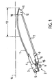
- the shaker as shown in Figure 1 consists of a flexible rod (1) made of ERTALON.
- This flexible rod (1) is fixed to an oscillating support (2) by means of a fixing shell (3) and a sleeve reinforced with ERTALON (4).
- the flexible rod (1) is engaged in the fixing shell (3) and is held by gluing, by a locking screw or by any suitable means known in the state of the art.
- the fixing shell (3) is connected to the oscillating support (2) by means of a vertical pivot (5).
- the oscillating support (2) is mounted on the vertical axis (6) of the harvesting machine.
- the shaker also comprises a fiberglass connecting rod (7), one of the ends of which is connected to the oscillating support (2) by means of a fixing shell (8).
- This fixing shell (8) comprises an adjustment and locking screw (9) making it possible to adjust the extension of the connecting rod (7).
- the other end of the connecting rod (7) is connected to the free end (10) of the flexible rod (1) by through a flange (11).
- This flange (11) is connected to the end of the connecting rod (7) by a vertical pivot (12).
- Adjusting the extension of the connecting rod (7) makes it possible to modify the profile of the flexible rod (1) so as to optimize the length of the active zone (13).
- This active area (13) corresponds to the portion that can come into contact with the vine planes aligned along an axis (14).
- the oscillating support (2) further comprises an adjustment screw (15) disposed substantially perpendicular to the axis of the holding rod (7) and the vertical axis (6).
- This adjustment screw (15) makes it possible to adjust the initial angle of the extension sleeve (4) relative to the axis of the connecting rod. By increasing this angle within a certain limit, the length of the active area (13) is increased.
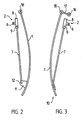
- FIG. 2 represents a variant of the invention.
- the oscillating support (2) comprises a single fixing shell (8) provided with a locking screw (9) of the connecting rod (7).
- This connecting rod (7) is driven by the oscillating movement imposed by the vertical axis (6).
- This oscillating movement is communicated to the flexible rod (1) via a flange (11) connected to the end of the retaining rod (7) by a vertical axis (12).
- the other end of the flexible rod (1) is fixed to the frame of the harvesting machine, in the plane containing the shaker, by means of a vertical pivot (16).
- the vertical axis (16) is disposed between the vertical median plane passing through the axis of the plantation and the parallel plane containing the vertical axis (6). This axis (16) is placed in front of the axis (6) of oscillation if we consider the direction of advance of the harvesting machine.
- FIG. 3 represents a third variant of the invention.
- the retaining rod (7) is connected to the free end of the flexible rod (1) by a fixed connection, for example a bolt or a non-articulated flange.
- the opposite end of the flexible rod (1) is connected to a vertical pivot (16) by means of a link (17).
- This rod (17) pivots on the one hand around the vertical axis (16) and on the other hand around a vertical axis (18) fixed on the end of the flexible rod (1).
- This link (17) consists of a rigid piece of metal.
- the shaker shown in Figure 4 consists of a flexible rod (1) having a first segment (20) substantially straight, a second segment (21) forming a curve of about 180 ° and a third segment (22) substantially straight.
- the first segment (20) has at its free end (23) a convex part seen from the side of the vegetation (24).
- This convex part (23) is substantially tangent to the center line (25) of the vegetation (24) when the shaker is in contact with the vegetation.
- This first part (20) continues with a second part (21) forming an angle of approximately 180 °, facing the side opposite to the vegetation.
- the third part (22) is connected to this second curved part (21) and has one end secured to the oscillating support (2).
- the flexible rod is made of ERTALON (registered trademark) distributed in particular by the company Cestidur.
- the curvature of the flexible rod is produced by thermoforming, by immersing the ERTALON rod in boiling water.
- the oscillating support has a first sleeve (27) into which one end of the flexible rod is threaded. The other end is threaded into a second sleeve (28).
- the sleeves of the locking screws (29, 30) used to secure the flexible rod with the oscillating support when the latter is in place.
- the oscillating support comprises an adjustment screw (31) making it possible to adjust the relative angle between the longitudinal axis (32) of the first part (20) of the flexible rod and the longitudinal axis (33) of the third part (22) of said flexible rod. By adjusting this angle (34), of course, the angle between each of the axes is also adjusted. longitudinal (32, 33) and the median longitudinal axis (35) of the shaker (1).
- the transverse elastic modulus in particular the elastic modulus in the horizontal plane of the flexible rod forming the shaker, is chosen so that the shocks caused by the contact of the free end on the vegetation are absorbed by the flexible rod, but that the latter substantially retains its initial shape.
- the transverse elasticity module in the vertical plane is chosen so that the flexible rod (1) is self-supporting, and its free end remains substantially in the plane generated by the longitudinal axes (32 and 33) of the sleeves (28 and 29).
- the two transverse elasticity modules are identical when it is a rod made of a homogeneous material, but may be different in the case of cutting from a laminated material or from multilayer or multifiber structures.
- FIG. 5 represents a top view of another variant of the shaker.
- the flexible rod (20) is connected to the oscillating support (2) via a rigid rod (7) connected to the free end (37) of the flexible rod via a joint (38) .
- This articulation (38) comprises a pivot (39) perpendicular to the plane defined by the flexible rod (20) and by the rigid rod (7).
- the opposite end of the rod (7) cooperates with the oscillating support (2) via a guide (40) having an orifice (41) inside which its end can slide.
- Thrust springs (42, 43) are arranged on either side of the guide (40).
- the end of the rod (7) has threads (44, 45). Filtered nuts (46, 47) constitute the stops of the springs (42, 43).
- the modification of the longitudinal position of the nuts (46, 47) modifies on the one hand the return force of the springs (42, 43), and on the other hand the extension at rest of the rigid rod (7).
- the adjustment of the longitudinal elongation of the rigid rod (7) makes it possible to define the camber at rest of the flexible rod (20).
Landscapes
- Life Sciences & Earth Sciences (AREA)
- Environmental Sciences (AREA)
- Soil Working Implements (AREA)
- Harvesting Machines For Root Crops (AREA)
- Preparation Of Fruits And Vegetables (AREA)
- Apparatuses For Bulk Treatment Of Fruits And Vegetables And Apparatuses For Preparing Feeds (AREA)
- Food-Manufacturing Devices (AREA)
- Harvester Elements (AREA)
Applications Claiming Priority (2)
| Application Number | Priority Date | Filing Date | Title |
|---|---|---|---|
| FR8914056A FR2653636B2 (fr) | 1989-04-18 | 1989-10-26 | Secoueur et machine a vendanger a tige flexible. |
| FR8914056 | 1989-10-26 |
Publications (2)
| Publication Number | Publication Date |
|---|---|
| EP0425353A1 true EP0425353A1 (de) | 1991-05-02 |
| EP0425353B1 EP0425353B1 (de) | 1995-04-26 |
Family
ID=9386813
Family Applications (1)
| Application Number | Title | Priority Date | Filing Date |
|---|---|---|---|
| EP90402952A Expired - Lifetime EP0425353B1 (de) | 1989-10-26 | 1990-10-19 | Rüttler und Maschine zur Traubenernte mit einem solchen Rüttler |
Country Status (4)
| Country | Link |
|---|---|
| EP (1) | EP0425353B1 (de) |
| AT (1) | ATE121589T1 (de) |
| DE (1) | DE69018928T2 (de) |
| ES (1) | ES2073551T3 (de) |
Cited By (1)
| Publication number | Priority date | Publication date | Assignee | Title |
|---|---|---|---|---|
| FR2752666A1 (fr) * | 1996-08-27 | 1998-03-06 | Gregoire Ets | Secoueur pour machine a vendanger ou a recolter des fruits ou des baies par secouage, procede de fabrication d'un tel secoueur, et moule pour la fabrication d'un tel secoueur |
Citations (6)
| Publication number | Priority date | Publication date | Assignee | Title |
|---|---|---|---|---|
| FR2605488A1 (fr) * | 1986-10-27 | 1988-04-29 | Braud Sa | Machine pour la recolte des fruits, baies et similaires portes par des arbres et arbustes fruitiers plantes en ligne |
| EP0267829A1 (de) * | 1986-10-27 | 1988-05-18 | Hesston Braud | Erntemaschine für Früchte, Beeren und ähnliche, getragen von Bäumen und Sträuchern in Reihenaufstellung |
| SU1445615A1 (ru) * | 1987-07-23 | 1988-12-23 | Центр Внедрения Научной Организации Производства И Труда | Рабочий орган виноградоуборочной машины |
| FR2638600A1 (fr) * | 1988-11-09 | 1990-05-11 | Bobard Jeune Sa Ets | Dispositif de secouage pour machines a cueillir des baies, notamment des raisins |
| FR2638602A1 (fr) * | 1988-11-10 | 1990-05-11 | Fourcade Christian | Machine a vendanger |
| FR2639177A1 (fr) * | 1988-11-18 | 1990-05-25 | Bobard Jeune Sa Ets | Dispositif de secouage pour machines a vendanger ou autres machines pour recolter des fruits |
-
1990
- 1990-10-19 EP EP90402952A patent/EP0425353B1/de not_active Expired - Lifetime
- 1990-10-19 DE DE69018928T patent/DE69018928T2/de not_active Expired - Lifetime
- 1990-10-19 ES ES90402952T patent/ES2073551T3/es not_active Expired - Lifetime
- 1990-10-19 AT AT90402952T patent/ATE121589T1/de not_active IP Right Cessation
Patent Citations (6)
| Publication number | Priority date | Publication date | Assignee | Title |
|---|---|---|---|---|
| FR2605488A1 (fr) * | 1986-10-27 | 1988-04-29 | Braud Sa | Machine pour la recolte des fruits, baies et similaires portes par des arbres et arbustes fruitiers plantes en ligne |
| EP0267829A1 (de) * | 1986-10-27 | 1988-05-18 | Hesston Braud | Erntemaschine für Früchte, Beeren und ähnliche, getragen von Bäumen und Sträuchern in Reihenaufstellung |
| SU1445615A1 (ru) * | 1987-07-23 | 1988-12-23 | Центр Внедрения Научной Организации Производства И Труда | Рабочий орган виноградоуборочной машины |
| FR2638600A1 (fr) * | 1988-11-09 | 1990-05-11 | Bobard Jeune Sa Ets | Dispositif de secouage pour machines a cueillir des baies, notamment des raisins |
| FR2638602A1 (fr) * | 1988-11-10 | 1990-05-11 | Fourcade Christian | Machine a vendanger |
| FR2639177A1 (fr) * | 1988-11-18 | 1990-05-25 | Bobard Jeune Sa Ets | Dispositif de secouage pour machines a vendanger ou autres machines pour recolter des fruits |
Cited By (2)
| Publication number | Priority date | Publication date | Assignee | Title |
|---|---|---|---|---|
| FR2752666A1 (fr) * | 1996-08-27 | 1998-03-06 | Gregoire Ets | Secoueur pour machine a vendanger ou a recolter des fruits ou des baies par secouage, procede de fabrication d'un tel secoueur, et moule pour la fabrication d'un tel secoueur |
| EP0832550A1 (de) * | 1996-08-27 | 1998-04-01 | Etablissements Gregoire S.A. | Schüttler für eine Traubenerntemaschine oder für eine Obst- oder Beerenerntemaschine, Verfahren zur Herstellung solchen Schüttlers, und Form für diese Herstellung |
Also Published As
| Publication number | Publication date |
|---|---|
| ATE121589T1 (de) | 1995-05-15 |
| DE69018928D1 (de) | 1995-06-01 |
| DE69018928T2 (de) | 1995-12-21 |
| ES2073551T3 (es) | 1995-08-16 |
| EP0425353B1 (de) | 1995-04-26 |
Similar Documents
| Publication | Publication Date | Title |
|---|---|---|
| EP0266259B1 (de) | Erntemaschine für Früchte, Beeren und ähnliche, getragen von Bäumen und Sträuchern in Reihenaufstellung | |
| EP2008147B1 (de) | Randlose brillen mit bügeln einer im wesentlichen filamentären struktur | |
| FR3062927A1 (fr) | Monture de lunettes a orientation des branches selon plusieurs plans | |
| EP1266723B1 (de) | Werkstückhalter für eine Augenoptik | |
| FR2800173A1 (fr) | Monture de lunettes et lunettes pourvues d'une telle monture | |
| EP0208608A1 (de) | Antiresonanzaufhängungsvorrichtung mit sechs Freiheitsgraden für einen Hubschrauber | |
| FR2776307A1 (fr) | Mecanisme de tirage pour mecanique d'armure et metier a tisser comprenant un tel mecanisme de tirage | |
| EP0425353B1 (de) | Rüttler und Maschine zur Traubenernte mit einem solchen Rüttler | |
| EP0328171A1 (de) | Halterung von Schabeblättern zum Reinigen von Förderbändern | |
| CA2673759C (fr) | Tronconneuse de rail ou analogue | |
| FR2645701A1 (fr) | Secoueur et machine a vendanger equipee d'un tel secoueur | |
| FR2712817A3 (fr) | Système pour agir sur les propriétés vibratoires d'un ski. | |
| FR2747098A1 (fr) | Dispositif de suspension d'une boite de transmission d'un aeronef a voilure tournante | |
| FR2653636A2 (fr) | Secoueur et machine a vendanger a tige flexible. | |
| EP0147363A1 (de) | Verfahren und Vorrichtung zur Positionierung einer optischen Faser bezüglich eines anderen optischen Bestandteiles | |
| EP1988195B1 (de) | Verbindungsstange für Zugsystem und Webrahmen, der eine solche Verbindungsstange umfasst | |
| EP0385822A1 (de) | Brillenbügel und dazu passendes Brillengestell | |
| FR2860387A1 (fr) | Dispositif de fixation amovible des doigts de secouage des peignes mobiles d'appareils de recolte aerienne de petits fruits | |
| EP1719700A2 (de) | Haltesvorrichtung für eine Flugzeugbatterie | |
| FR2654575A1 (fr) | Perfectionnements aux dispositifs de secouage lateral pour machines a recolter des fruits, notamment des machines a vendanger. | |
| FR2816234A1 (fr) | Dispositif de suspension d'une lame d'une scie a chantourner a parallelogramme | |
| FR2641158A1 (fr) | Dispositif de secouage pour machine a recolter les baies | |
| EP0832550B1 (de) | Schüttler für eine Traubenerntemaschine oder für eine Obst- oder Beerenerntemaschine und Form für diese Herstellung | |
| EP1554625A1 (de) | Abschirmung für brillen und komponenten zur herstellung einer solchen abschirmung | |
| FR2666192A2 (fr) | Perfectionnements aux dispositifs de secouage laterale pour machines a recolter des fruits notamment des machines a vendanger. |
Legal Events
| Date | Code | Title | Description |
|---|---|---|---|
| PUAI | Public reference made under article 153(3) epc to a published international application that has entered the european phase |
Free format text: ORIGINAL CODE: 0009012 |
|
| AK | Designated contracting states |
Kind code of ref document: A1 Designated state(s): AT CH DE ES IT LI |
|
| 17P | Request for examination filed |
Effective date: 19911018 |
|
| 17Q | First examination report despatched |
Effective date: 19930201 |
|
| GRAA | (expected) grant |
Free format text: ORIGINAL CODE: 0009210 |
|
| AK | Designated contracting states |
Kind code of ref document: B1 Designated state(s): AT CH DE ES IT LI |
|
| REF | Corresponds to: |
Ref document number: 121589 Country of ref document: AT Date of ref document: 19950515 Kind code of ref document: T |
|
| REF | Corresponds to: |
Ref document number: 69018928 Country of ref document: DE Date of ref document: 19950601 |
|
| ITF | It: translation for a ep patent filed | ||
| REG | Reference to a national code |
Ref country code: ES Ref legal event code: FG2A Ref document number: 2073551 Country of ref document: ES Kind code of ref document: T3 |
|
| PLBE | No opposition filed within time limit |
Free format text: ORIGINAL CODE: 0009261 |
|
| STAA | Information on the status of an ep patent application or granted ep patent |
Free format text: STATUS: NO OPPOSITION FILED WITHIN TIME LIMIT |
|
| 26N | No opposition filed | ||
| PGFP | Annual fee paid to national office [announced via postgrant information from national office to epo] |
Ref country code: CH Payment date: 19981127 Year of fee payment: 9 |
|
| PG25 | Lapsed in a contracting state [announced via postgrant information from national office to epo] |
Ref country code: LI Free format text: LAPSE BECAUSE OF NON-PAYMENT OF DUE FEES Effective date: 19991031 Ref country code: CH Free format text: LAPSE BECAUSE OF NON-PAYMENT OF DUE FEES Effective date: 19991031 |
|
| REG | Reference to a national code |
Ref country code: CH Ref legal event code: PL |
|
| PGFP | Annual fee paid to national office [announced via postgrant information from national office to epo] |
Ref country code: ES Payment date: 20091117 Year of fee payment: 20 Ref country code: DE Payment date: 20091015 Year of fee payment: 20 Ref country code: AT Payment date: 20091013 Year of fee payment: 20 |
|
| PGFP | Annual fee paid to national office [announced via postgrant information from national office to epo] |
Ref country code: IT Payment date: 20091015 Year of fee payment: 20 |
|
| PG25 | Lapsed in a contracting state [announced via postgrant information from national office to epo] |
Ref country code: DE Free format text: LAPSE BECAUSE OF EXPIRATION OF PROTECTION Effective date: 20101019 |
|
| REG | Reference to a national code |
Ref country code: ES Ref legal event code: FD2A Effective date: 20140826 |
|
| PG25 | Lapsed in a contracting state [announced via postgrant information from national office to epo] |
Ref country code: ES Free format text: LAPSE BECAUSE OF EXPIRATION OF PROTECTION Effective date: 20101020 |