EP0425377A1 - Verfahren und Vorrichtung zum Formen von Bauelementen - Google Patents
Verfahren und Vorrichtung zum Formen von Bauelementen Download PDFInfo
- Publication number
- EP0425377A1 EP0425377A1 EP90403002A EP90403002A EP0425377A1 EP 0425377 A1 EP0425377 A1 EP 0425377A1 EP 90403002 A EP90403002 A EP 90403002A EP 90403002 A EP90403002 A EP 90403002A EP 0425377 A1 EP0425377 A1 EP 0425377A1
- Authority
- EP
- European Patent Office
- Prior art keywords
- mold
- block
- walls
- molding
- forming
- Prior art date
- Legal status (The legal status is an assumption and is not a legal conclusion. Google has not performed a legal analysis and makes no representation as to the accuracy of the status listed.)
- Withdrawn
Links
- 238000000465 moulding Methods 0.000 title claims abstract description 79
- 238000000034 method Methods 0.000 title claims abstract description 19
- 239000000463 material Substances 0.000 claims abstract description 7
- 239000012778 molding material Substances 0.000 claims description 3
- 238000000605 extraction Methods 0.000 claims description 2
- 238000005266 casting Methods 0.000 claims 1
- 238000009416 shuttering Methods 0.000 claims 1
- 230000001502 supplementing effect Effects 0.000 claims 1
- 238000004519 manufacturing process Methods 0.000 abstract description 6
- 238000010276 construction Methods 0.000 description 6
- 238000006073 displacement reaction Methods 0.000 description 4
- 230000000903 blocking effect Effects 0.000 description 3
- 238000009415 formwork Methods 0.000 description 3
- 238000011065 in-situ storage Methods 0.000 description 3
- 238000007711 solidification Methods 0.000 description 3
- 230000008023 solidification Effects 0.000 description 3
- 238000010438 heat treatment Methods 0.000 description 2
- 230000002787 reinforcement Effects 0.000 description 2
- 238000005096 rolling process Methods 0.000 description 2
- 239000007787 solid Substances 0.000 description 2
- 238000003466 welding Methods 0.000 description 2
- 238000007796 conventional method Methods 0.000 description 1
- 238000009434 installation Methods 0.000 description 1
- 238000012797 qualification Methods 0.000 description 1
- 230000003014 reinforcing effect Effects 0.000 description 1
- 230000000087 stabilizing effect Effects 0.000 description 1
- XLYOFNOQVPJJNP-UHFFFAOYSA-N water Substances O XLYOFNOQVPJJNP-UHFFFAOYSA-N 0.000 description 1
Images



Classifications
-
- B—PERFORMING OPERATIONS; TRANSPORTING
- B28—WORKING CEMENT, CLAY, OR STONE
- B28B—SHAPING CLAY OR OTHER CERAMIC COMPOSITIONS; SHAPING SLAG; SHAPING MIXTURES CONTAINING CEMENTITIOUS MATERIAL, e.g. PLASTER
- B28B7/00—Moulds; Cores; Mandrels
- B28B7/22—Moulds for making units for prefabricated buildings, i.e. units each comprising an important section of at least two limiting planes of a room or space, e.g. cells; Moulds for making prefabricated stair units
-
- E—FIXED CONSTRUCTIONS
- E04—BUILDING
- E04G—SCAFFOLDING; FORMS; SHUTTERING; BUILDING IMPLEMENTS OR AIDS, OR THEIR USE; HANDLING BUILDING MATERIALS ON THE SITE; REPAIRING, BREAKING-UP OR OTHER WORK ON EXISTING BUILDINGS
- E04G11/00—Forms, shutterings, or falsework for making walls, floors, ceilings, or roofs
- E04G11/02—Forms, shutterings, or falsework for making walls, floors, ceilings, or roofs for rooms as a whole by which walls and floors are cast simultaneously, whole storeys, or whole buildings
Definitions
- the present invention relates generally to a method of molding a building block, for example of concrete, as well as to a device for implementing this method.
- This invention applies, for example, to the production of premises for residential or office use.
- the present invention aims to provide a method of molding a building block, for example concrete, and a device for its implementation, which allow the realization "in situ" of building blocks both simple, solid, inexpensive to produce and advantageously defining a habitable space.
- the subject of the present invention is a method of molding a building block constituted by a plate from which projecting elements are perpendicular or not, this method consisting in installing a mold with pivoting walls, at a location where said block must be permanently installed; lifting the mold cavity from the mold relative to a transport frame for this mold; unfolding and blocking said pivoting walls so as to form the molding cavity delimiting the contour of the plate and of the bearing elements of the block; optionally adjusting, in at least one horizontal and vertical direction, said mold cavity relative to the transport frame; pouring a molding material, for example concrete, into the molding cavity; folding the pivoting walls back to their initial position to release the plate and the load-bearing elements of the solidified block; to lower the mold cavity to detach it from the solidified block; and extracting the mold from the solidified block by passage between the load-bearing elements of said block.
- the walls are unfolded along a substantially horizontal axis to form the plate of the block, and the pivoting walls are unfolded along a substantially vertical axis to bring them closer to one another in order to define in the molding cavity part of this cavity which delimits the bearing elements of the block.
- This method is further characterized in that, after extraction of the mold from the solidified building block, the mold is juxtaposed with this block so that at least two walls pivoting along the above-mentioned substantially vertical axis enclose at least one of the carrier elements of said previously solidified block, then a second building block is molded adjacent to the first and having at least one common carrier element with the first block.
- the invention also relates to a molding device for implementing the method meeting the above characteristics, this device being constituted by a transportable mold comprising a molding cavity with articulated walls and means of transport and positioning of the mold relative to the ground.
- the mold comprises a molding cavity mounted relatively mobile on a chassis comprising on the one hand a substantially horizontal upper wall forming a receptacle for molding material such as concrete, and provided with flaps forming flaps articulated along a substantially horizontal axis and d secondly a plurality of double walls capable of pivoting along a substantially vertical axis and communicating with said upper wall forming a receptacle in the unfolded position thereof to allow the molding of a building block constituted by a plate comprising load-bearing elements protruding from this plateau.
- This device is further characterized in that the aforementioned chassis supports at least one carriage, coupled to the upper part forming the mold receptacle by articulated arms to allow the relative displacement of the molding cavity relative to the chassis.
- this device is characterized in that between the aforementioned carriage and the mold chassis is provided a second carriage movable relative to the first carriage in a direction orthogonal thereto.
- this device comprises formwork elements completing the above-mentioned double walls in the lower part of the mold.
- blocking means such as for example jacks, keep the flaps and the aforementioned double walls of the mold in the unfolded or folded position.
- This device is further characterized in that the mold is equipped with wheels and supports suitable means supply and treatment of concrete connected to an energy source, such as for example, solar collectors.
- the chassis is supported by several seats forming air cushions.
- Each seat forming an air cushion is fixed to the chassis by means of a ball-joint element.
- each element forming a ball joint consists of an upright or the like, secured to the chassis and swiveling in a housing secured to each seat.
- the seats forming air cushions are for example four in number, and are fixed permanently or removably to the chassis.
- a molding device which is essentially constituted by a transportable mold 1 which comprises a frame 5 and a molding cavity 2.
- this transportable mold 1 has at its upper part the molding cavity 2 for receiving concrete or any other moldable material.
- This molding cavity 2 has at its top an upper wall 3 on which are laterally mounted, pivoting about axes 4a and 4b parallel to the two longitudinal edges of the upper wall 3, two walls forming flap 3a and 3b.
- the longitudinal axes 4a and 4b extend substantially horizontally to allow the flaps 3a and 3b to pivot towards a position called “molding position", that is to say a position raised, so that the upper surface of the flaps is in a horizontal plane comprising the wall 3, as can be seen on the left side of FIG. 1.
- the flaps 3a and 3b can also be folded against the mold towards a so-called position "transport position" of this mold, as illustrated on the right-hand side of FIG. 1.
- the mold cavity 2 is mounted movably on the frame 5 which will be described later.
- Locking members 6a and 6b serve to selectively lock the flaps 3a and 3b in the upper molding or folded down transport position. These locking members 6a and 6b are respectively pivotally mounted at their upper end under the flaps 3a and 3b and at their lower end on the chassis 5.
- the molding cavity 2 has four double walls 7a, 7b pivotally mounted on the frame 5 so that it can be selectively unfolded in the molding position ( Figure 3) or folded against the frame 5 in the transport (figure 2).
- These double walls 7a, 7b are constituted by an external flap 7a and an internal flap 7b.
- These flaps 7a and 7b are each articulated about a vertical axis 8 and form in the molding position, that is to say in the contiguous position, the vertical and lower part of the molding cavity 2.
- the space between the flaps 7a and 7b communicates in the upper part with the upper part of the molding cavity 2 formed by the upper wall 3 and the flaps 3a and 3b described above.
- Locking latches make it possible to immobilize the double walls 7a, 7b in the molding or transport position of the mold 1.
- the horizontal upper part of the molding cavity 2 formed by the walls 3, 3a and 3b has on certain parts of its periphery flanges 2b corresponding to the thickness of the upper horizontal part of the building block. to mold.
- longitudinal and transverse grooves 10 are formed in the horizontal upper part of the molding cavity 2 to form reinforcing ribs on the corresponding part of the building block to be molded.
- the frame 5 on which the molding cavity 2 is mounted has an upper support 11 as can be seen in FIG. 3, which is fixed, for example by welding, to the upper wall 3 of the molding cavity 2.
- This support 11 has at its front and rear ends (FIGS. 2 and 3), support beams 12 on which the double walls 7a, 7b of the molding cavity 2 are articulated as described above.
- the upper support 11 is itself supported by a mechanism for adjusting the height of the molding cavity 2 constituted by articulated arms 13 forming compasses. These compasses are mounted articulated between, on the one hand the upper support 11 and on the other hand a carriage 14 which will be described below.
- the compasses 13, the carriage 14 and the upper support 11 together form deformable polygons allowing the height adjustment of the molding cavity relative to the carriage 14.
- the carriage 14 is provided with rollers 16 guided in rails 17 forming part of a second carriage 18 arranged under the first carriage 14.
- the rollers 16 thus guided allow the longitudinal displacement of the carriage 14 relative to the second carriage 18 which will be described now. It will be specified that the first carriage 14 can roll on the second carriage 18 which can itself roll on the lower part or base 21 of the chassis 5.
- the carriage 18 has rollers 19 guided in rails 20 integral with the base 21 and orthogonal to the rails 17, so that the carriage 18 can move in a direction perpendicular to the direction of movement of the carriage 14.
- wheels have been shown fixed under the base 21 of the chassis 5 and allowing the transport by rolling of the whole of the molding device according to the invention.
- the base 21 of the chassis 5 is further equipped with a system of retractable crutches 24 making it possible to stabilize the mold 1 in a fixed position relative to the ground.
- various pieces of equipment can be mounted on the mold 1, such as a concrete pump, a vibrator or a system for heating the molding cavity 2.
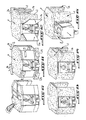
- the molding device which has just been described above makes it possible to manufacture building blocks B such as that clearly visible in FIG. 15 and comprising in particular a horizontal plate P and vertical support elements E protruding, according to the example of embodiment shown, perpendicular to the plate P and intended to rest, for example, on the ground.
- the mold 1 is moved using the wheels 22 and 23, the walls of which are closed in the transport position up to the location S of the building, represented by dotted lines, where the building block B will be molded
- this location S is located on an already existing construction, such as for example another solidified building block B.
- a foundation such as a concrete slab or a foundation under each vertical support element at the location S chosen to rest the building block that we want to mold.
- the crutches 24 are placed so as to stabilize the mold 1 relative to the ground, as is sees well in Figure 5, and thus avoid unwanted movement during subsequent molding operations.
- the first walls placed in the molding position are the flaps 3a and 3b. To achieve this, these flaps are raised to a substantially horizontal position using jacks 6a and 6b ( Figure 1) which also block the flaps.
- the four double walls 7a, 7b forming the lower part of the cavity 2 and serving to mold the support elements E of the building block B are then unfolded as seen in FIG. 7 in the molding position.
- the outer flaps 7a are pivoted about the axes 8 from their folded position against the ends of the chassis 5 to a position of coincidence with the flaps 3a and 3b.
- the interior flaps 7b are pivoted about their axes 8 from their folded position between the frame 5 to a position of contact with the exterior flaps to define with them a molding space communicating with the upper part of the molding cavity 2 and allowing the molding in a single block of the support elements E and of the plate P of the block.
- the internal flaps 7b and that the external flaps 7a are, in the molding position, immobilized by latches (not shown).
- the lifting operation is carried out by deforming, using a crank (not shown), the compasses constituted by the articulated arms 13 in the direction indicated by the arrows H in FIG. 8.
- the carriages 14 and 18 are immobilized relative to the base 21 of the chassis 5 using, for example, brakes (not shown) blocking the rotation of the rollers 16 and 19.
- a concrete pouring operation can then be carried out, as shown very schematically in FIG. 10, which concrete fills all the space defined by the double walls 7a, 7b, the wall 3, the flaps 3a, 3b, the flanges 2b and the forms 25 and 26.
- Reinforcement reinforcements (not shown) can be placed in the molding cavity 2 before the latter is filled with concrete up to the top of the flanges 2b.
- the concrete can then be vibrated inside the molding cavity 2 so as to make it more homogeneous.
- a vibrator of the type used in construction can be installed, for example, on the molding cavity 2.
- a heating system for the mold cavity 2 which may for this purpose include electrical resistors arranged near the locations to be heated from the mold 1 and integral with this mold so as to keep the concrete block B frost-free or even to accelerate its solidification.
- Solar water collectors (not shown) can also be placed near the mold 1 so as to advantageously provide the necessary heat.
- All mold equipment requiring electric current supply can advantageously be supplied with current using autonomous means (not shown).
- the formwork elements 25 and 26 are then disassembled, as can be seen in FIG. 11.
- the double walls 7a, 7b are opened. so as to release the supporting elements E from the building block B, as can be seen in FIG. 12.
- the double walls 7a and 7b are folded back by pivoting the flaps 7a and 7b around their axes 8 until '' they are placed against the frame 5 of the mold 1.
- FIG. 13 shows the operation of lowering the molding cavity 2 relative to the chassis 5. This operation is carried out by acting on the articulated arms 13 of the compasses in the opposite direction to that previously described for the lifting operation .
- the arrow A in FIG. 13 illustrates the deformation of the articulated arms 13 and the lowering of the molding cavity 2.
- it is essential to lower the cavity 2 by a height such that the wall 3 and the flaps 3a and 3b are lower than the lower part of the ribs of the plate P resulting from the molding of the concrete in the grooves 10.
- the mold 1 is extracted by rolling it between the bearing elements E of the block of construction B.
- a building block B which alone can constitute the framework of a building such as, for example, a detached house, it being understood that it will suffice to closing, with prefabricated elements for example, the lateral openings delimited by the load-bearing elements E.
- this method and this device also advantageously make it possible to produce a building block B which can serve as a reference for the positioning of the mold 1 in order to proceed with a new molding operation so as to form, for example, a building made up of several building blocks B placed side by side.
- the mold 1 is juxtaposed with a building block B previously molded.
- the procedure for adjusting the position of the mold cavity 2 relative to the frame 5 is carried out in the same way as described above, so as to place the mold cavity 2 in a position such that one can enclose one of the carrier elements E of the building block B already solidified between the exterior flaps 7a and interior 7b of one of the double walls 7a, 7b.
- the different walls of the mold 1 are then installed in the molding position as illustrated in FIGS. 4 to 7.
- a second building block is molded adjacent to the first solidified block and therefore having a supporting element E in common with the first block.
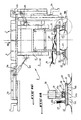
- FIGS. 16 to 18 represent another embodiment of the support and displacement means on the floor of the device according to this invention, and which bear the same references to designate the common elements.
- Each seat 40 is integral with a frame or the like 30 connected to the support 11 by means of the mechanism with articulated arms 13 allowing the height adjustment of the molding cavity.
- each seat forming an air cushion can be fixed permanently or removably to the chassis 5.
- each seat forming an air cushion 40 is constituted by a plate 42 under which a skirt 43 is fixed.
- the skirt 43 rests itself on a support plane of the mold 1, such as for example the ground.
- a flexible pipe 44 for supplying compressed air is fixed on the plate 42 and communicates with a chamber 45 formed in this plate.
- the bottom wall of the plate 42 has a plurality of holes 46 which connect the chamber 45 to the space delimited by the skirt 43, between the plate 42 and the bearing plane of the mold.
- Each support plate 42 is articulated on the frame 30 by means of a ball-joint element 50.
- This element 50 comprises an upright 51 or the like, which is fixed, for example by welding, to the frame 30, and which extends substantially vertically from the lower part thereof. It will be specified here that the seats forming air cushions can also be detachably fixed to the chassis 5.
- the lower end of the upright 51 has the shape of a hemisphere 52 which is connected to the upright by a portion of reduced section 53.
- a housing 41 is mounted with clearance on the upright 51 at the portion of reduced section 53 which passes through a bore 41b of the upper wall 41a of the housing 41.
- the hemisphere 52 can come into contact with the lower wall 41c of the housing, thanks to the mounting clearance of the part 53 in the bore 51b.
- the lower wall 41c of the housing is fixed to the support plate 42 to thereby produce a swiveling connection.
- the air cushion 40 can automatically adapt to the irregularities of the surface on which the mold 1 rests to facilitate its movement, as for example in the case where it is desired to move the mold on an inclined plane. It is thus possible to avoid any recourse to an additional displacement system such as a crane, when it is desired to load the mold on a vehicle for example.
- the mold 1 is equipped with four seats forming air cushions 40 arranged in the vicinity of the four corners of the frame 30, which is for example rectangular.
- Each air cushion 40 is connected, by through its supply line 44 to a pressure distributor 60.
- the pressure distributor 60 is itself connected by a flexible conduit 61 to an internal compressor shown schematically at 70 in FIG. 17.
- This compressed air supply system has two main advantages. First of all thanks to the distributor 60, it is possible to balance the pressures in the air cushions 40 to give the chassis 5 perfect stability. Then, it is possible to use a compressor of the type of those commonly used on construction sites, this compressor can also be used for other purposes than feeding the air cushions, for example to vibrate the material to be molded.
- this block can have a polygonal or other shape and include supporting elements E perpendicular or not at the P stage of the block.
Landscapes
- Engineering & Computer Science (AREA)
- Architecture (AREA)
- Mechanical Engineering (AREA)
- Manufacturing & Machinery (AREA)
- Chemical & Material Sciences (AREA)
- Ceramic Engineering (AREA)
- Civil Engineering (AREA)
- Structural Engineering (AREA)
- Moulds, Cores, Or Mandrels (AREA)
Applications Claiming Priority (4)
| Application Number | Priority Date | Filing Date | Title |
|---|---|---|---|
| FR8913998A FR2653376B1 (fr) | 1989-10-25 | 1989-10-25 | Procede et dispositif pour le moulage de blocs de construction. |
| FR8913998 | 1989-10-25 | ||
| FR9012430 | 1990-10-09 | ||
| FR9012430A FR2667534B2 (fr) | 1989-10-25 | 1990-10-09 | Procede et dispositif pour le moulage de blocs de construction. |
Publications (1)
| Publication Number | Publication Date |
|---|---|
| EP0425377A1 true EP0425377A1 (de) | 1991-05-02 |
Family
ID=26227621
Family Applications (1)
| Application Number | Title | Priority Date | Filing Date |
|---|---|---|---|
| EP90403002A Withdrawn EP0425377A1 (de) | 1989-10-25 | 1990-10-24 | Verfahren und Vorrichtung zum Formen von Bauelementen |
Country Status (2)
| Country | Link |
|---|---|
| EP (1) | EP0425377A1 (de) |
| FR (1) | FR2667534B2 (de) |
Cited By (4)
| Publication number | Priority date | Publication date | Assignee | Title |
|---|---|---|---|---|
| ES2132015A1 (es) * | 1996-12-02 | 1999-08-01 | Fernandez Jose Maria Villar | Encofrado para hormigon y similares. |
| WO2003090986A1 (en) * | 2002-04-24 | 2003-11-06 | David Anthony Dicesare | Vertical casting apparatus and method |
| CN113459254A (zh) * | 2021-07-09 | 2021-10-01 | 北京好运达智创科技有限公司 | 一种装配式盖梁分体模具 |
| WO2024223773A1 (de) * | 2023-04-25 | 2024-10-31 | Redima Ag | Deckentisch für betondeckenschalungen |
Citations (9)
| Publication number | Priority date | Publication date | Assignee | Title |
|---|---|---|---|---|
| BE710121A (de) * | 1968-01-30 | 1968-05-30 | ||
| FR2091938A1 (de) * | 1970-05-26 | 1971-01-21 | Materiel Special Entrepr | |
| FR2289704A1 (fr) * | 1974-10-29 | 1976-05-28 | Auxiliaire Entreprises Soc | Procede de construction utilisant des moules tridimensionnels retractables et moules correspondants |
| FR2296070A2 (fr) * | 1974-12-27 | 1976-07-23 | Auxiliaire Entreprises Soc | Procede de construction utilisant des moules tridimensionnels retractables et moules correspondants |
| NL8105300A (nl) * | 1981-11-23 | 1983-06-16 | Maco Veenendaal B V | Bekistingsvoet. |
| CA1151406A (en) * | 1982-11-18 | 1983-08-09 | Mikhail Linetsky | Precast house making plant |
| NL8201173A (nl) * | 1982-03-22 | 1983-10-17 | Hubert Adriaan Van Strien | Werkwijze voor het construeren van een bouwwerk. |
| GB2162229A (en) * | 1984-07-24 | 1986-01-29 | Aero Go Limited | Improvements relating to scaffolding |
| WO1986004540A1 (en) * | 1985-02-04 | 1986-08-14 | James Dudley Day | Apparatus and method for constructing modular pre-cast concrete buildings |
Family Cites Families (1)
| Publication number | Priority date | Publication date | Assignee | Title |
|---|---|---|---|---|
| CA115406A (en) * | 1908-04-07 | 1908-12-01 | Isaac Emerson Palmer | Thread guide |
-
1990
- 1990-10-09 FR FR9012430A patent/FR2667534B2/fr not_active Expired - Lifetime
- 1990-10-24 EP EP90403002A patent/EP0425377A1/de not_active Withdrawn
Patent Citations (9)
| Publication number | Priority date | Publication date | Assignee | Title |
|---|---|---|---|---|
| BE710121A (de) * | 1968-01-30 | 1968-05-30 | ||
| FR2091938A1 (de) * | 1970-05-26 | 1971-01-21 | Materiel Special Entrepr | |
| FR2289704A1 (fr) * | 1974-10-29 | 1976-05-28 | Auxiliaire Entreprises Soc | Procede de construction utilisant des moules tridimensionnels retractables et moules correspondants |
| FR2296070A2 (fr) * | 1974-12-27 | 1976-07-23 | Auxiliaire Entreprises Soc | Procede de construction utilisant des moules tridimensionnels retractables et moules correspondants |
| NL8105300A (nl) * | 1981-11-23 | 1983-06-16 | Maco Veenendaal B V | Bekistingsvoet. |
| NL8201173A (nl) * | 1982-03-22 | 1983-10-17 | Hubert Adriaan Van Strien | Werkwijze voor het construeren van een bouwwerk. |
| CA1151406A (en) * | 1982-11-18 | 1983-08-09 | Mikhail Linetsky | Precast house making plant |
| GB2162229A (en) * | 1984-07-24 | 1986-01-29 | Aero Go Limited | Improvements relating to scaffolding |
| WO1986004540A1 (en) * | 1985-02-04 | 1986-08-14 | James Dudley Day | Apparatus and method for constructing modular pre-cast concrete buildings |
Cited By (4)
| Publication number | Priority date | Publication date | Assignee | Title |
|---|---|---|---|---|
| ES2132015A1 (es) * | 1996-12-02 | 1999-08-01 | Fernandez Jose Maria Villar | Encofrado para hormigon y similares. |
| WO2003090986A1 (en) * | 2002-04-24 | 2003-11-06 | David Anthony Dicesare | Vertical casting apparatus and method |
| CN113459254A (zh) * | 2021-07-09 | 2021-10-01 | 北京好运达智创科技有限公司 | 一种装配式盖梁分体模具 |
| WO2024223773A1 (de) * | 2023-04-25 | 2024-10-31 | Redima Ag | Deckentisch für betondeckenschalungen |
Also Published As
| Publication number | Publication date |
|---|---|
| FR2667534A2 (fr) | 1992-04-10 |
| FR2667534B2 (fr) | 1993-01-22 |
Similar Documents
| Publication | Publication Date | Title |
|---|---|---|
| EP2710207A1 (de) | Vorrichtung zum zumindest teilweisen verschliessen eines oben offenen hohlraums | |
| EP0619773B1 (de) | Verfahren und vorrichtung zum herstellen von baublöcken aus einem hydraulischen bindemittel wie gips, einem inerten material wie sand und wasser | |
| BE620670A (de) | ||
| FR2659593A1 (fr) | Dispositif pour la fabrication automatique de produits en beton moule necessitant un demoulage par retournement. | |
| FR2507506A1 (fr) | Laminoir continu a cages croisees pour la production de tubes sans soudure | |
| BE1005071A5 (fr) | Appareil de moulage de resine synthetique. | |
| BE663028A (de) | ||
| FR2653376A1 (fr) | Procede et dispositif pour le moulage de blocs de construction. | |
| FR2724920A1 (fr) | Palonnier et installation pour la manutention de charges lourdes, telles que moteurs d'avion | |
| FR2667534A2 (fr) | Procede et dispositif pour le moulage de blocs de construction. | |
| EP0251878A1 (de) | Verfahren und Vorrichtung zum Formen von Gehäusen, Kästen oder Schränken, und erhaltenes Gehäuse | |
| EP0094465A1 (de) | Verfahren zur Herstellung von Konstruktionsplatten hergestellte Platten und Vorrichtung zur Ausführung des Verfahrens | |
| EP0136241B1 (de) | Vorrichtung für die Produktion von einstückigen Elementen bestimmt zur Herstellung von Grabgewölben | |
| FR2824772A1 (fr) | Procede et dispositif de fabrication d'elements de construction | |
| FR2740377A1 (fr) | Procede de moulage d'elements en beton et dispositif pour sa mise en oeuvre | |
| CH714545A2 (fr) | Presse à brique en terre crue compressée. | |
| BE1001496A7 (fr) | Batiment prefabrique. | |
| FR2730513A1 (fr) | Procede de construction d'un sol en beton d'une structure et dispositif utilise pour celui-ci | |
| FR2789930A1 (fr) | Dispositif de fabrication de grands parpaings en beton a dimensions exactes | |
| EP0286764A1 (de) | Transportsystem für Fertighäuser, Fertighaus mit Vorrichtungen für sein Transport und Fertigungsverfahren für ein solches Haus | |
| FR2641303A1 (fr) | Coffrages metalliques pour la prefabrication d'elements en beton de section rectangulaire et de forme allongee | |
| EP3546168A1 (de) | Vorrichtung zum formen einer schale für ein einschaliges poolbecken | |
| FR2513562A1 (fr) | Moule multiple pour la fabrication de pieces en platre | |
| FR2563204A1 (fr) | Accessoire pour chariot a fourche, et procede de dechargement utilisant cet accessoire | |
| FR2970984A1 (fr) | Procede de construction d'une structure dans lequel on construit au moins un poteau vertical et on l'assemble a au moins une poutre horizontale |
Legal Events
| Date | Code | Title | Description |
|---|---|---|---|
| PUAI | Public reference made under article 153(3) epc to a published international application that has entered the european phase |
Free format text: ORIGINAL CODE: 0009012 |
|
| AK | Designated contracting states |
Kind code of ref document: A1 Designated state(s): AT BE CH DE DK ES GB GR IT LI LU NL SE |
|
| STAA | Information on the status of an ep patent application or granted ep patent |
Free format text: STATUS: THE APPLICATION IS DEEMED TO BE WITHDRAWN |
|
| 18D | Application deemed to be withdrawn |
Effective date: 19911105 |