EP0425399B1 - Aktenschranktyp - Google Patents
Aktenschranktyp Download PDFInfo
- Publication number
- EP0425399B1 EP0425399B1 EP90450013A EP90450013A EP0425399B1 EP 0425399 B1 EP0425399 B1 EP 0425399B1 EP 90450013 A EP90450013 A EP 90450013A EP 90450013 A EP90450013 A EP 90450013A EP 0425399 B1 EP0425399 B1 EP 0425399B1
- Authority
- EP
- European Patent Office
- Prior art keywords
- door
- column
- panels
- central
- plate
- Prior art date
- Legal status (The legal status is an assumption and is not a legal conclusion. Google has not performed a legal analysis and makes no representation as to the accuracy of the status listed.)
- Expired - Lifetime
Links
- 238000005096 rolling process Methods 0.000 claims description 26
- 230000003014 reinforcing effect Effects 0.000 claims description 6
- 238000006073 displacement reaction Methods 0.000 claims description 4
- 238000000926 separation method Methods 0.000 claims 1
- 238000004519 manufacturing process Methods 0.000 description 3
- 210000000056 organ Anatomy 0.000 description 2
- BASFCYQUMIYNBI-UHFFFAOYSA-N platinum Chemical compound [Pt] BASFCYQUMIYNBI-UHFFFAOYSA-N 0.000 description 2
- 230000002787 reinforcement Effects 0.000 description 2
- 238000005452 bending Methods 0.000 description 1
- 239000002184 metal Substances 0.000 description 1
- 125000006850 spacer group Chemical group 0.000 description 1
- 230000000007 visual effect Effects 0.000 description 1
Images
Classifications
-
- A—HUMAN NECESSITIES
- A47—FURNITURE; DOMESTIC ARTICLES OR APPLIANCES; COFFEE MILLS; SPICE MILLS; SUCTION CLEANERS IN GENERAL
- A47B—TABLES; DESKS; OFFICE FURNITURE; CABINETS; DRAWERS; GENERAL DETAILS OF FURNITURE
- A47B49/00—Revolving cabinets or racks; Cabinets or racks with revolving parts
-
- A—HUMAN NECESSITIES
- A47—FURNITURE; DOMESTIC ARTICLES OR APPLIANCES; COFFEE MILLS; SPICE MILLS; SUCTION CLEANERS IN GENERAL
- A47F—SPECIAL FURNITURE, FITTINGS, OR ACCESSORIES FOR SHOPS, STOREHOUSES, BARS, RESTAURANTS OR THE LIKE; PAYING COUNTERS
- A47F5/00—Show stands, hangers, or shelves characterised by their constructional features
- A47F5/02—Rotary display stands
Definitions
- the present invention relates to a cabinet of the filing cabinet type comprising an enclosure in which are arranged several circular drums spaced from each other and mounted in rotation on a vertical central column.
- the enclosure of this type of cabinet consists of two diametrically opposite vertical panels erected between a base to which they are attached and an upper cover element.
- the two vertical panels provide between them two diametrically opposite openings each capable of being closed by a door, sliding in the enclosure and on upper and lower rails.
- Such a piece of furniture is described in particular in patent FR-A-2481904.
- the various elements of the enclosure namely the vertical panels, the closing doors and the guide rails are bent in an arc of circumference coaxial with the central column.
- the object of the present invention is to obviate the aforementioned drawbacks by implementing a filing cabinet of the aforementioned type which is extendable and / or retractable to receive both trays of large diameters and trays of small diameters without as much generate space losses.
- the cabinet according to the present invention of the cupboard type comprises a base on which are mounted, diametrically opposite with respect to a vertical central column carrying rotary drums, two curved vertical panels joined at the upper end by a plate fixed to the central column and defining between them two diametrically opposite openings which can be closed by two curved doors slidably mounted in the volume defined by the panels, said doors being provided with lower and upper rolling members which cooperate respectively with lower guide rails and upper internal to the cabinet, said cabinet being further capped by a cover.
- Such a cabinet will be able to receive either trays of large diameters (for example 900 mm) and trays of smaller diameter (for example 700 mm) without resulting in the creation of excessive volumes unusable for classification or storage, since the dimensions of the enclosure defined by the panels and doors are adaptable to the diameter of the drums.
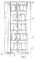
- the cabinet type filing cabinet comprises a base 1 on which are mounted, diametrically opposite with respect to a vertical central column 2 carrying rotary drums 3, two curved vertical panels 4 joined at the end upper by a plate 5 fixed to the central column 2 and defining between them two diametrically opposite openings 6 closable by two curved doors 7 slidably mounted in the volume defined by the panels 4, said doors 7 being provided with lower rolling members 8 and upper 9 which cooperate respectively with lower 10 and upper 11 guide rails internal to the cabinet, said cabinet being further capped by a cover 12.
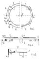
- the panels 4 are fixed to the base 1 and to the plate 5 in a removable manner and so as to be able to be brought closer or apart from the central column 2 by displacement along a diametrical axis and be locked in position.
- the rolling members 8 and 9 fitted to the port 7 can occupy on their support at least two distinct positions according to one of which they are separated from the door and according to the other, close together, which makes it possible, depending on the position they take care of removing door 7 from central column 2 or bringing it closer in order to adapt the position occupied by door 7 relative to the central column, to the position occupied by panels 4.
- the cover 12 comprises a central part 12A and two lateral parts 12B fixed to the central part so as to be able to be moved apart or brought closer to one another along the same diametrical axis of spacing or bringing together the panels 4.
- the base 1 is in the general form of a cross and comprises a vertical central orifice in which is fixed by any means known to those skilled in the art the terminal portion of the central column vertical 2.
- This column can be formed by abutment of tubular elements.
- the plates 3 have a central orifice and a tubular element extending axially upwards this central orifice.
- the tray by its central opening and by its tubular element is fitted on the central column.
- Between two contiguous plates 3 is placed on the column a ball stop so as to facilitate the rotation of each plate.
- the plate 5, mounted for fixing in any known manner at the upper end of the column 2, is constituted by a metal plate of rectangular shape for example. This plate extends along a horizontal plane and is centered relative to the column.
- a circular plate coaxial with the column which carries along its perimeter edge the lower guide rail 10 common to the two doors 7.
- This rail advantageously has a cross section in "U” and follows the outline of a coaxial circle to the column.
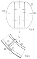
- Each panel 4 along a vertical axis is bent along an arc of circumference eccentric with respect to the column.
- the value of the radius of this arc of circumference is greater than the value of the smallest distance between column 2 and the curved part of the panel.
- each panel has, along its vertical sides, two vertical returns 13 which, when the panel is arranged in its most distant position from the column, are each arranged in a vertical plane radial to the column.
- the panel comprises a ribbed reinforcing element 14 constituted for example by a "U" profile curved according to a bending radius identical to the radius of the arc of circumference along which the panel 4 develops.
- Each panel 4 is fixed to the upper plate 5 and to the base 1 in a removable manner and as said previously with the possibility of approaching or spacing relative to the central column and locking in position.
- each panel 4 is provided with two lower horizontal lugs 15 for fixing to the base 1 and two upper horizontal lugs 16 for fixing to the plate 5, each of these lugs 15 or 16 carrying a fixing bolt either to the plate, or to the base.
- the plate 5 and the base 1 are provided with oblong slots 17, 18 which receive the fixing bolts. These lights extend in directions parallel to the direction of movement of the panels 4 relative to the central column.
- the length of the oblong lights is identical to the interval separating the two extreme positions that the panel can occupy.
- the panels 4 delimit two diametrically opposite openings 6 each closable by a door 7.
- Each door 7 is curved along an arc of circumference which is coaxial with the column 2 when the door is arranged in its most distant position from the column 2.
- the arc of circumference along which each door is bent has a length greater than the arc of circumference along which each opening develops whether the panels 4 are in the most distant position or the closest to the column.
- Each door along its vertical edges has a return at right angles to the column and along its upper and lower horizontal edges of the reinforcement elements bent along an arc of circumference of the same radius as the arc of circumference along which it develops.
- Each reinforcing element can be a curved profile, of cross section in "U".
- the door is equipped with two horizontal upper supports 19 each carrying an upper rolling member 9, these horizontal supports developing towards the central column 2 and two lower supporting elements 20 each receiving a lower rolling member 8.
- each upper rolling member 9 is oriented so that its axis of rotation is vertical. This member enters the upper guide rail 11 and cooperates in rotation with the outer side of this rail.
- Each support 19 is preferably constituted by a horizontal tab fixed to the upper reinforcement element and by at least two parallel vertical axes 19A spaced from one another, one of these axes being more spaced from the door than the 'other and one of these axes depending on the spacing of the door relative to the central column being intended to removably receive the rolling member.
- the upper rolling member will be disposed on the axis closest to the door when the latter must occupy the position closest to the central column while the axis furthest from the door will receive the rolling when the door should occupy the most distant position.
- Each lower rolling member 8 is positioned so that its axis of rotation is horizontal.
- the lower support 20 of each lower rolling member 9 is removably fixed to the lower reinforcing element of the door.
- each lower support 20 comprises a plate 21 to which is fixed a pin 22 on which is mounted in free manner in translation the lower rolling member 8 so that according to one or other of the positions of the door relative to the central column the lower rolling member 8 cooperating with this axis 22 can always be brought into the lower guide rail 10.
- the rolling member cooperates with translational stop members known per se which may be constituted by a spacer threaded on the axis 22 and positioned between the plate 21 and the said member and by a removable pin coming in front of said member 8.
- the axis 22 is fixed obliquely to the plate and the latter is supported and removably fixed on a suitable slope 23 formed on the lower reinforcing element, which allows by rotation of the plate assembly and axis following a half-turn in one direction or the other depending on whether the door is in the close position or away from the column, to orient the axis of rotation of the rolling member always in a secant manner to the geometric axis of column 2.
- This slope 23 relative to the tangent to the point of intersection of the geometric axis of axis 22 with the curved surface of the door, is inclined by an angle whose value is equal to the value of the half-angle that must describe the geometric axis of axis 22, in order to be brought in a secant fashion to the axis of the column, when the door is arranged in its position closest to this column.
- the axis 22 will be inclined by the value of the abovementioned half-angle.
- the cover 12 is removably mounted on the plate 5.
- this cover 12 is provided with a downwardly projecting perimeter rim covering the upper edge of the side panels 4 and the openings.
- the rim which comprises the lateral elements 12B covers the upper edge of the side panels 4, while the lateral rims which comprises the central element 12A cover the upper edges of the openings (6),
- the central element 12A partially covers the lateral elements 12B and these lateral elements 12B each comprise two bolts for fixing to the central element, these bolts each engaging in an oblong slot made in the central element. This light extends parallel to the diametrical axis of movement of the panels (4).
- the extensible piece of furniture as described above although given to receive two types of rotary drums differentiated by their diameter, may receive in addition to the types already indicated other types of drums of a different diameter.
- the oblong lights of the plate and the base may have visual cues materializing the different positions that the panels can occupy and the upper supports 19 will be equipped with as many vertical axes as there are positions provided.
Landscapes
- Assembled Shelves (AREA)
- Saccharide Compounds (AREA)
- Details Of Audible-Bandwidth Transducers (AREA)
- Securing Of Glass Panes Or The Like (AREA)
Claims (9)
- Ordnungsmöbel vom Schranktyp mit einem Sockel (1), auf dem bezüglich einer vertikalen zentralen Säule (2), die Drehtrommeln (3) trägt zwei gekrümmte vertikale Paneele (4) diametral entgegengesetzt angebracht sind, die am oberen Ende durch eine an der zentralen Säule (2) befestigte Platte (5) vereinigt sind und zwischen ihnen zwei diametral entgegengesetzte Öffnungen (6) bilden, die durch zwei gekrümmte Türen (7) verschlossen werden können, die in dem durch die Paneele (4) gebildeten Raum gleitend gelagert sind, wobei die Türen (7) mit einem unteren (8) und einem oberen Rollorgan (9) versehen sind, die mit einer unteren (10) bzw. oberen Führungsschiene (11) innerhalb des Schranks zusammenwirken, wobei der Schrank darüberhinaus durch einen Deckel (12) abgedeckt und dadurch gekennzeichnet ist, daß:- die Paneele (4) am Sockel (1) und an der Platte (5) derart befestigt sind, daß sie durch Verschiebung nach einer diametralen Achse an die zentrale Säule (2) angenähert oder davon entfernt werden und an Position blockiert werden können,- die Rollorgane (8) und (9), mit denen die Türe (7) ausgestattet ist an ihrem Träger wenigstens zwei verschiedene Positionen einnehmen können, wobei sie nach der einen von der Türe entfernt und nach der anderen an sie angenähert sind, womit es nach der Position, die sie einnehmen, möglich wird, die Tür (7) von der zentralen Säule zu entfernen oder sie daran anzunähern, um die von der Tür bezüglich der zentralen Säule eingenommene Position an die von den Paneelen (4) eingenommene Position anzupassen,- und daß der Deckel (12) einen zentralen Teil (12A) und zwei seitliche Teile (12B) aufweist, die am zentralen Teil derart befestigt sind, daß sie nach der gleichen diametralen Achse zum Entfernen oder Annähern der Paneele (4) voneinander entfernt oder einander angenähert werden können.
- Ordnungsmöbel nach Anspruch 1, dadurch gekennzeichnet, daß die vertikalen Paneele (4) und die Türen (7) nach einem Umfangsbogen gekrümmt sind, daß der Umfangsbogen, nach dem jede Türe gekrümmt ist, zu der Säule koaxial ist, wenn die Türe nach ihrer am weitesten von der Säule entfernten Position angeordnet ist, und daß der Umfangsbogen, nach dem jedes Paneel (4) gekrümmt ist, bezüglich der Säule exzentriert ist, wobei der Wert des Radius dieses Umfangsbogens über dem Wert der kleinsten Entfernung zwischen der Säule und dem gekrümmten Teil des Paneels liegt.
- Ordnungsmöbel nach Anspruch 1, dadurch gekennzeichnet, daß jedes Paneel (4) mit zwei unteren horizontalen Klammern (15) zur Befestigung am Sockel (1) und zwei oberen horizontalen Klammern (16) zur Befestigung an der Platine (5) versehen ist, wobei jede dieser Klammern (15) oder (16) einen Bolzen zur Befestigung an der Platte oder am Sockel trägt, und daß die Platte (5) und der Sockel (1) gegenüber der Befestigungsklammer (15) oder (16) mit Langlöchern (17), (18) versehen sind, die die Befestigungsbolzen aufnehmen, wobei sich die Löcher entlang zur Richtung der Verschiebung der Paneele (4) bezüglich der zentralen Säule paralleler Richtungen erstrecken.
- Ordnungsmöbel nach Anspruch 3, dadurch gekennzeichnet, daß die Länge der Langlöcher (17), (18) mit dem Abstand identisch ist, der die beiden Extrempositionen trennt, die das Paneel einnehmen kann.
- Ordnungsmöbel nach Anspruch 1, dadurch gekennzeichnet, daß der Umfangsbogen, nach dem jede Türe gekrümmt ist, eine Länge aufweist, die über dem Umfangsbogen liegt, nach dem sich jede Öffnung (6) abwickelt.
- Ordnungsmöbel nach Anspruch 1, dadurch gekennzeichnet, daß jede Türe mit zwei horizonalen oberen Trägern (19) ausgestattet ist, die jeweils ein oberes Rollorgan (9) tragen, wobei sich diese horizontalen Träger zu der zentralen Säule (2) hin abwickeln und von zwei unteren Trägerelementen (20) jeweils eines ein unteres Rollorgan (8) aufnimmt,- daß jedes obere Rollorgan (9) derart gerichtet ist, daß seine Rotationsachse vertikal liegt;- und daß jedes untere Rollorgan (8) derart positioniert ist, daß seine Rotationsachse horizontal liegt.
- Ordnungsmöbel nach Anspruch 6, dadurch gekennzeichnet, daß jeder Träger (19) durch eine horizontale Klammer, die an dem oberen Verstärkungselement befestigt ist, sowie durch wenigstens zwei parallele vertikale Achsen gebildet ist, die voneinander beabstandet sind, wobei eine dieser Achsen von der Türe weiter entfernt ist als die andere und eine dieser Achsen in Abhängigkeit von der Entfernung der Türe bezüglich der zentralen Säule dazu bestimmt ist, das obere Rollorgan abnehmbar aufzunehmen.
- Ordnungsmöbel nach Anspruch 6, dadurch gekennzeichnet, daß jeder untere Träger (20) eine Platte (21) aufweist, an der eine Achse (22) befestigt ist, an der das untere Rollorgan (8) in freier Translation derart angebracht ist, daß, je nach der einen oder anderen der Positionen der Türe bezüglich der zentralen Säule, das mit dieser Achse (22) zusammenwirkende untere Rollorgan in die untere Führungsschiene gebracht werden kann, und daß die Achse (22) schief zu der Platte befestigt ist, und daß diese abnehmbar an einer geeigneten Steigung (23) anliegt und befestigt ist, die an dem unteren Verstärkungselement angebracht ist, mit dem die Türe (7) ausgestattet ist, womit es durch Drehung der Einheit aus der Platte und der Achse um eine halbe Drehung in der einen oder anderen Richtung, je nachdem, ob sich die Türe in der an die Säule angenäherten oder in der davon entfernten Position befindet, möglich wird, die Rotationsachse des Rollorgans immer sekantenweise zur geometrischen Achse der Säule (2) zu orientieren.
- Ordnungsmöbel nach Anspruch 1, dadurch gekennzeichnet, daß:- der Deckel (12) mit einem nach unten vorspringenden Umfangsrand versehen ist, der die obere Umrandung der seitlichen Paneele (4) und der Öffnungen überdeckt, wobei der Rand, den die seitlichen Elemente (12B) aufweisen, die obere Umrandung der seitlichen Paneele (4) überdecken, während die seitlichen Ränder, die das zentrale Element (12A) aufweist, die oberen Umrandungen der Öffnungen (6) überdecken,- das zentrale Element (12A) teilweise die seitlichen Elemente (12B) überdeckt,- daß diese seitlichen Elemente (12B) jeweils zwei Bolzen zur Befestigung an dem zentralen Element aufweisen, daß diese Bolzen jeweils in ein Langloch eingreifen, das in dem zentralen Element vorgesehen ist;- und daß sich dieses Langloch parallel zur diametralen Verschiebungsachse der Paneele (4) erstreckt.
Applications Claiming Priority (2)
| Application Number | Priority Date | Filing Date | Title |
|---|---|---|---|
| FR8914375 | 1989-10-23 | ||
| FR8914375A FR2653316B1 (fr) | 1989-10-23 | 1989-10-23 | Meuble du type armoire de classement. |
Publications (2)
| Publication Number | Publication Date |
|---|---|
| EP0425399A1 EP0425399A1 (de) | 1991-05-02 |
| EP0425399B1 true EP0425399B1 (de) | 1995-04-05 |
Family
ID=9387026
Family Applications (1)
| Application Number | Title | Priority Date | Filing Date |
|---|---|---|---|
| EP90450013A Expired - Lifetime EP0425399B1 (de) | 1989-10-23 | 1990-10-22 | Aktenschranktyp |
Country Status (6)
| Country | Link |
|---|---|
| EP (1) | EP0425399B1 (de) |
| AT (1) | ATE120623T1 (de) |
| CA (1) | CA2028193C (de) |
| DE (1) | DE69018370T2 (de) |
| ES (1) | ES2073555T3 (de) |
| FR (1) | FR2653316B1 (de) |
Families Citing this family (2)
| Publication number | Priority date | Publication date | Assignee | Title |
|---|---|---|---|---|
| GB2356802A (en) * | 1999-12-03 | 2001-06-06 | Deborah Anne Sadler | Furniture made from oil drums |
| DE10056507A1 (de) * | 2000-11-15 | 2002-05-29 | Averbeck Alfred | Möbelstück, das um seine vertikale Mittelachse drehbar ist |
Family Cites Families (2)
| Publication number | Priority date | Publication date | Assignee | Title |
|---|---|---|---|---|
| FR1306104A (fr) * | 1961-08-31 | 1962-10-13 | Dequeker S A | Bac extensible pour classement de documents |
| FR2481904B1 (fr) * | 1980-05-12 | 1985-11-08 | Daigre Jean Claude | Meuble du type armoire |
-
1989
- 1989-10-23 FR FR8914375A patent/FR2653316B1/fr not_active Expired - Fee Related
-
1990
- 1990-10-22 CA CA002028193A patent/CA2028193C/fr not_active Expired - Fee Related
- 1990-10-22 AT AT90450013T patent/ATE120623T1/de not_active IP Right Cessation
- 1990-10-22 ES ES90450013T patent/ES2073555T3/es not_active Expired - Lifetime
- 1990-10-22 EP EP90450013A patent/EP0425399B1/de not_active Expired - Lifetime
- 1990-10-22 DE DE69018370T patent/DE69018370T2/de not_active Expired - Fee Related
Also Published As
| Publication number | Publication date |
|---|---|
| CA2028193C (fr) | 1999-06-08 |
| CA2028193A1 (fr) | 1991-04-24 |
| ATE120623T1 (de) | 1995-04-15 |
| ES2073555T3 (es) | 1995-08-16 |
| EP0425399A1 (de) | 1991-05-02 |
| FR2653316A1 (fr) | 1991-04-26 |
| DE69018370T2 (de) | 1995-12-14 |
| DE69018370D1 (de) | 1995-05-11 |
| FR2653316B1 (fr) | 1992-02-14 |
Similar Documents
| Publication | Publication Date | Title |
|---|---|---|
| EP0049665B1 (de) | Schaugestell mit Fachböden | |
| EP1166687B1 (de) | Warenschaustand | |
| EP0707681B1 (de) | Schiebeflügel und eckstück dafür | |
| FR2508291A1 (fr) | Meuble comportant un plateau reglable pour l'amenagement d'un poste de travail en construction modulaire | |
| FR2760802A1 (fr) | Dispositif d'assemblage et element modulaire le comprenant | |
| EP0008970A1 (de) | Metallschrank | |
| EP0425399A1 (de) | Aktenschranktyp | |
| EP2340742B1 (de) | Verkaufsständer zum Präsentieren und/oder Ordnen | |
| FR2958521A1 (fr) | Dispositif de liaison ou d'extension pour modules de preparation et de cuisson | |
| EP0684672A1 (de) | Gehäuse, insbesondere für Niederspannungsgeräte | |
| FR2638145A1 (fr) | Appareil de distribution automatique de documents | |
| EP0388302B1 (de) | Rundtisch mit einem Ring abnehmbarer Zusatzplatten | |
| EP1005809B1 (de) | Standfeste, seitlich ausfahrbare Vorrichtung in der Art eines Büros oder eines Tisches | |
| FR2632839A1 (fr) | Dispositif a plateau tournant pour placards | |
| FR2647328A1 (fr) | Presentoir pour bouteilles | |
| EP0577466A1 (de) | Drehbarer Aktenschrank mit schneller Montage | |
| EP1694172B1 (de) | Vorrichtung zur darbietung von gegenständen | |
| FR2648030A1 (fr) | Presentoir antivol pour lunettes | |
| EP0807542A1 (de) | Lastförderwagen mit Befestigungsmitteln | |
| FR2762977A1 (fr) | Table a rallonges | |
| FR2481904A1 (fr) | Meuble du type armoire | |
| FR2782350A1 (fr) | Dispositif de fixation amovible de deux elements plats, notamment de chants d'une etagere sur des montants | |
| FR2649659A1 (fr) | Chariot pliant | |
| EP0785738A1 (de) | Starres untergestell für bürotisch mit zweiseitig verwendbarer arbeitsplatte | |
| FR2682724A1 (fr) | Dispositif de fixation amovible d'un element sur un support. |
Legal Events
| Date | Code | Title | Description |
|---|---|---|---|
| PUAI | Public reference made under article 153(3) epc to a published international application that has entered the european phase |
Free format text: ORIGINAL CODE: 0009012 |
|
| AK | Designated contracting states |
Kind code of ref document: A1 Designated state(s): AT BE CH DE DK ES FR GB GR IT LI LU NL SE |
|
| 17P | Request for examination filed |
Effective date: 19910603 |
|
| RBV | Designated contracting states (corrected) |
Designated state(s): AT BE CH DE ES FR GB GR IT LI LU NL SE |
|
| 17Q | First examination report despatched |
Effective date: 19940921 |
|
| GRAA | (expected) grant |
Free format text: ORIGINAL CODE: 0009210 |
|
| AK | Designated contracting states |
Kind code of ref document: B1 Designated state(s): AT BE CH DE ES FR GB GR IT LI LU NL SE |
|
| PG25 | Lapsed in a contracting state [announced via postgrant information from national office to epo] |
Ref country code: GR Free format text: LAPSE BECAUSE OF FAILURE TO SUBMIT A TRANSLATION OF THE DESCRIPTION OR TO PAY THE FEE WITHIN THE PRESCRIBED TIME-LIMIT Effective date: 19950405 Ref country code: AT Effective date: 19950405 |
|
| REF | Corresponds to: |
Ref document number: 120623 Country of ref document: AT Date of ref document: 19950415 Kind code of ref document: T |
|
| REF | Corresponds to: |
Ref document number: 69018370 Country of ref document: DE Date of ref document: 19950511 |
|
| ITF | It: translation for a ep patent filed | ||
| PG25 | Lapsed in a contracting state [announced via postgrant information from national office to epo] |
Ref country code: SE Effective date: 19950705 |
|
| REG | Reference to a national code |
Ref country code: ES Ref legal event code: FG2A Ref document number: 2073555 Country of ref document: ES Kind code of ref document: T3 |
|
| GBT | Gb: translation of ep patent filed (gb section 77(6)(a)/1977) |
Effective date: 19950726 |
|
| PLBE | No opposition filed within time limit |
Free format text: ORIGINAL CODE: 0009261 |
|
| STAA | Information on the status of an ep patent application or granted ep patent |
Free format text: STATUS: NO OPPOSITION FILED WITHIN TIME LIMIT |
|
| 26N | No opposition filed | ||
| PGFP | Annual fee paid to national office [announced via postgrant information from national office to epo] |
Ref country code: DE Payment date: 19960607 Year of fee payment: 6 |
|
| PG25 | Lapsed in a contracting state [announced via postgrant information from national office to epo] |
Ref country code: DE Effective date: 19970701 |
|
| PGFP | Annual fee paid to national office [announced via postgrant information from national office to epo] |
Ref country code: ES Payment date: 19971113 Year of fee payment: 8 |
|
| PGFP | Annual fee paid to national office [announced via postgrant information from national office to epo] |
Ref country code: GB Payment date: 19971121 Year of fee payment: 8 |
|
| PGFP | Annual fee paid to national office [announced via postgrant information from national office to epo] |
Ref country code: NL Payment date: 19971130 Year of fee payment: 8 |
|
| PG25 | Lapsed in a contracting state [announced via postgrant information from national office to epo] |
Ref country code: GB Free format text: LAPSE BECAUSE OF NON-PAYMENT OF DUE FEES Effective date: 19981022 |
|
| PG25 | Lapsed in a contracting state [announced via postgrant information from national office to epo] |
Ref country code: ES Free format text: LAPSE BECAUSE OF NON-PAYMENT OF DUE FEES Effective date: 19981023 |
|
| PG25 | Lapsed in a contracting state [announced via postgrant information from national office to epo] |
Ref country code: NL Free format text: LAPSE BECAUSE OF NON-PAYMENT OF DUE FEES Effective date: 19990501 |
|
| GBPC | Gb: european patent ceased through non-payment of renewal fee |
Effective date: 19981022 |
|
| NLV4 | Nl: lapsed or anulled due to non-payment of the annual fee |
Effective date: 19990501 |
|
| PGFP | Annual fee paid to national office [announced via postgrant information from national office to epo] |
Ref country code: LU Payment date: 20011030 Year of fee payment: 12 |
|
| PGFP | Annual fee paid to national office [announced via postgrant information from national office to epo] |
Ref country code: BE Payment date: 20011116 Year of fee payment: 12 |
|
| REG | Reference to a national code |
Ref country code: CH Ref legal event code: PUEA Free format text: JEAN CLAUDE DAIGRE;SOCIETE DACOTA SUD OUEST S.A. TRANSFER- SOCIETE DACOTA SUD OUEST S.A.;N.R.C., EURL |
|
| REG | Reference to a national code |
Ref country code: FR Ref legal event code: TQ |
|
| PG25 | Lapsed in a contracting state [announced via postgrant information from national office to epo] |
Ref country code: LU Free format text: LAPSE BECAUSE OF NON-PAYMENT OF DUE FEES Effective date: 20021022 |
|
| PG25 | Lapsed in a contracting state [announced via postgrant information from national office to epo] |
Ref country code: BE Free format text: LAPSE BECAUSE OF NON-PAYMENT OF DUE FEES Effective date: 20021031 |
|
| BERE | Be: lapsed |
Owner name: *DAIGRE JEAN CLAUDE Effective date: 20021031 Owner name: SOC. *DACOTA SUD OUEST S.A. Effective date: 20021031 |
|
| REG | Reference to a national code |
Ref country code: ES Ref legal event code: FD2A Effective date: 19991113 |
|
| REG | Reference to a national code |
Ref country code: CH Ref legal event code: PUE Owner name: SOCIETE DACOTA SUD OUEST S.A. Free format text: SOCIETE DACOTA SUD OUEST S.A.#VACQUIERS#VILLEMUR-SUR-TARN (FR) $ N.R.C., EURL#LES AMANDIERS, LIEU-DIT CARNUS, LE FAU#82000 MONTAUBAN (FR) -TRANSFER TO- SOCIETE DACOTA SUD OUEST S.A.#VACQUIERS#VILLEMUR-SUR-TARN (FR) $ SARL ETA#2, RUE PORTE DU MOUSTIER#82000 MONTAUBAN (FR) |
|
| REG | Reference to a national code |
Ref country code: FR Ref legal event code: TQ |
|
| PG25 | Lapsed in a contracting state [announced via postgrant information from national office to epo] |
Ref country code: IT Free format text: LAPSE BECAUSE OF NON-PAYMENT OF DUE FEES;WARNING: LAPSES OF ITALIAN PATENTS WITH EFFECTIVE DATE BEFORE 2007 MAY HAVE OCCURRED AT ANY TIME BEFORE 2007. THE CORRECT EFFECTIVE DATE MAY BE DIFFERENT FROM THE ONE RECORDED. Effective date: 20051022 |
|
| PGFP | Annual fee paid to national office [announced via postgrant information from national office to epo] |
Ref country code: CH Payment date: 20091130 Year of fee payment: 20 |
|
| PGFP | Annual fee paid to national office [announced via postgrant information from national office to epo] |
Ref country code: FR Payment date: 20091030 Year of fee payment: 20 |
|
| REG | Reference to a national code |
Ref country code: CH Ref legal event code: PL |