EP0425497B2 - Ancre marine - Google Patents
Ancre marine Download PDFInfo
- Publication number
- EP0425497B2 EP0425497B2 EP89904584A EP89904584A EP0425497B2 EP 0425497 B2 EP0425497 B2 EP 0425497B2 EP 89904584 A EP89904584 A EP 89904584A EP 89904584 A EP89904584 A EP 89904584A EP 0425497 B2 EP0425497 B2 EP 0425497B2
- Authority
- EP
- European Patent Office
- Prior art keywords
- anchor
- shank
- fluke
- blades
- blade
- Prior art date
- Legal status (The legal status is an assumption and is not a legal conclusion. Google has not performed a legal analysis and makes no representation as to the accuracy of the status listed.)
- Expired - Lifetime
Links
- 241000935974 Paralichthys dentatus Species 0.000 claims abstract description 34
- 230000005484 gravity Effects 0.000 claims description 17
- 239000000463 material Substances 0.000 claims description 6
- 241000242541 Trematoda Species 0.000 claims description 4
- 238000005266 casting Methods 0.000 claims description 3
- 229910001385 heavy metal Inorganic materials 0.000 claims description 3
- 229910052751 metal Inorganic materials 0.000 claims description 3
- 239000002184 metal Substances 0.000 claims description 3
- 238000003466 welding Methods 0.000 claims description 3
- 238000004873 anchoring Methods 0.000 description 4
- 230000004048 modification Effects 0.000 description 3
- 238000012986 modification Methods 0.000 description 3
- 238000004519 manufacturing process Methods 0.000 description 2
- 230000035515 penetration Effects 0.000 description 2
- XLYOFNOQVPJJNP-UHFFFAOYSA-N water Substances O XLYOFNOQVPJJNP-UHFFFAOYSA-N 0.000 description 2
- 241000512259 Ascophyllum nodosum Species 0.000 description 1
- 241000196324 Embryophyta Species 0.000 description 1
- 240000007058 Halophila ovalis Species 0.000 description 1
- 229910000831 Steel Inorganic materials 0.000 description 1
- 238000010276 construction Methods 0.000 description 1
- 239000006260 foam Substances 0.000 description 1
- 238000010348 incorporation Methods 0.000 description 1
- 230000001788 irregular Effects 0.000 description 1
- 238000005304 joining Methods 0.000 description 1
- 238000003754 machining Methods 0.000 description 1
- 230000002035 prolonged effect Effects 0.000 description 1
- 239000012858 resilient material Substances 0.000 description 1
- 230000000717 retained effect Effects 0.000 description 1
- 238000005096 rolling process Methods 0.000 description 1
- 239000004576 sand Substances 0.000 description 1
- 239000010959 steel Substances 0.000 description 1
- 239000004575 stone Substances 0.000 description 1
- 229920002994 synthetic fiber Polymers 0.000 description 1
Images

Classifications
-
- B—PERFORMING OPERATIONS; TRANSPORTING
- B63—SHIPS OR OTHER WATERBORNE VESSELS; RELATED EQUIPMENT
- B63B—SHIPS OR OTHER WATERBORNE VESSELS; EQUIPMENT FOR SHIPPING
- B63B21/00—Tying-up; Shifting, towing, or pushing equipment; Anchoring
- B63B21/24—Anchors
- B63B21/30—Anchors rigid when in use
- B63B21/32—Anchors rigid when in use with one fluke
-
- B—PERFORMING OPERATIONS; TRANSPORTING
- B63—SHIPS OR OTHER WATERBORNE VESSELS; RELATED EQUIPMENT
- B63B—SHIPS OR OTHER WATERBORNE VESSELS; EQUIPMENT FOR SHIPPING
- B63B21/00—Tying-up; Shifting, towing, or pushing equipment; Anchoring
- B63B21/22—Handling or lashing of anchors
- B63B2021/222—Buoyancy elements adapted or used for manipulating anchors, e.g. buoyancy elements built-in, or connected to the anchor, and used for lifting or up-righting the same
Definitions
- This invention relates to anchors of the burying type and in particular to those of the C.Q.R. type.
- Some anchors of the burying type are also difficult or awkward to manufacture and/or handle. To achieve penetration existing anchors are usually pivotable or hinged about a point on the shank of the anchor. This results in anchors which are non-rigid and this can be dangerous when lifting of the anchor is required.
- bouyant centre of gravity means the apparent centre of gravity of the anchor when it is submerged in water.
- said buoyant centre of gravity is disposed on the fluke side of a line drawn between the leading end of the shank and a line of maximum blade width.
- the blades are curved metal sheets.
- the blades are welded together at a join on said median plane.
- the blades consist of flat or angled surfaces.
- the position of the buoyant centre of gravity can be varied by incorporating buoyant or semibuoyant materials within the shank or by removing material from shank to define holes therealong.
- the buoyant centre of gravity can be varied using material of different density. Conveniently this is achieved by disposing a heavy metal such as lead beneath the join of said blades.
- the shape of the flukes is such that when a pull is applied to the leading end of the shank when said anchor is lying on the seabed the apex penetrates the seafloor and the apex acts a a fulcrum on further pulling so that the fluke is self-burying.
- the anchor rotates upright with the shank uppermost because of the large surface area presented by the transverse portions of the blades as the pull is exerted at said leading end.
- the anchor is a one-piece casting.
- the anchor can be formed by welding the shank to the fluke to form a single unit.
- the shank incorporates a resilient portion therein to mimimise deformation to the shank if a pull is effected on the shank transverse to the usual line of action.
- a support member is coupled between the trailing ends of the blades, said support being connected between the underside surfaces at the trailing end of the blades.
- the shank includes connection means disposed on said shank for the securing of a pennant or trip cable.
- an anchor of the present invention With an anchor of the present invention the desirable characteristics of rapid rolling into the upright attitude from any attitude which the anchor may settle on the mooring bed with quick penetration of the pointed end of the fluke as the anchor is dragged, are retained and even improved to some extent as will be further explained hereinbelow.
- the anchor exhibits substantial resistance to "roll out” upon continued dragging and is able to maintain a relatively high anchoring force even when subjected to such dragging over an extended distance.
- outer fluke blade surfaces Whilst various shapes of outer fluke blade surfaces may be used within the scope of the present invention as defined herein, advantageously there is used a section of a generally conical or pyramidal or hexagonal surface generated from a point at the leading end of the shank, the eyelet, and the single apex and the outer trailing edges of blades lie on the surface of the cone.
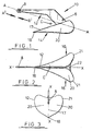
- Figs. 1 and 2 show one piece cast anchor 10 comprising a rigid elongated shank 12 connected to a fluke 14.
- the shank 12 is provided with an aperture means 6 for securing a pennant or trip cable (not shown).
- the shank 12 is additionally provided with connection means in the form of an elongated aperture or eyelet 8 for securing the main anchor cable.
- any form of anchor cable may be used including chain and steel or natural or synthetic fibre rope or hauser.
- the fluke 14 is in the form of a double bladed plough-share having two curved blades 16 as best shown in Fig. 2, which are symmetrically coupled about ridge 17 along median plane X-X. As best depicted in Figs. 1 and 3, the blades 16 have a single apex defined by the pointed forward end 18 of the ploughshare.
- each blade 16 has, when viewed from above, a concave outer surface 20 extending rearwardly and outwardly from the shank 12 and plane X-X.
- the concave outer surface 20 Of each blade 16 presents a substantial surface area best seen in Fig. 3, extending transversely outwards with respect to the direction B 1 , along which the drag force is applied.
- Each blade terminates in a trailing edge 21, the underside convex surfaces of which are connected by a strut 22 to resist compressive forces acting on the blades 20 during drag.
- a buoyant centre of gravity C is defined between the fluke 14 and shank 12 as shown.
- the buoyant centre of gravity C causes the anchor 10 to land on the seabed and have three points of contact with the seabed which are: the eyelet 8 at the leading end of the shank 12, the single apex 18 of the plough, and one of the tails of either blade 16 so that the anchor will lie on its side on the seabed.
- a drag force is applied in direction B 1 .
- the surfaces 20 in contact with the seabed in combination with apex 18 reacts such that downward forces are created on the anchor and the apex 18 of the plough penetrates the seabed.
- the cross-section of the fluke 14 in proximity to the apex 18 is V-shaped and acts as a fulcrum and the surfaces 20 cause the anchor to rotate upright when pulled and the fulcrum provided by the apex 20, together with the line of action along B 1 results in the anchor becoming self-burying.
- the anchor As a continuing load is applied to the anchor, it moves in the general direction of the load creating a drag resistance. If the drag is uniform or increasing the anchor remains in the seabed securing the vessel.
- the shape of the blades 20 causes the anchor to remain upright, and self-alinged in the direction of pull. If the anchor encounters an obstruction the shape of the blades 16 causes the anchor to self-steer around the projection in the direction of pull. For example, if a stone obstructs the movement of the anchor 10 of a point on one of the blades 16 then the obstructed blade will "dig in" to the seabed, causing the other blade to work clear of the seabed and present an increase in the projected bladed area on the side opposite the obstruction. This together with the decrease in the projected blade area at the obstruction permits the anchor to bypass the obstruction. Once the anchor has passed the obstruction a higher degree force acting on the increased area causes the anchor to revert to its original stable attitude.
- the anchor chain is shortened until the vessel is positioned directly above the buried anchor. Further vertical pull on the line causes the anchor to rotate out of the seabed into an upwards direction such that the 'V' shaped fluke orientation and apex 18 are generally vertical and this minimises resistance to lifting the anchor out of the seabed.
- the shank is conveniently in the form of a plate member and this requires minimal machining in its manufacture.
- the fluke is conveniently in the form of two sheet metal plates bent to the required dished, irregular conic, form and welded together along the central ridge.
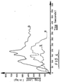
- FIG.4 compares the performance of an anchor of the invention (Q) with two previously known burying anchors according to UK patent No. 415176 (R) and UK Patent No. 1356259 (S), all of approximately similar weight in the region of 10kg.
- drag load in (in kg) is plotted against time (in seconds) corresponding to the duration of continued dragging to which the anchor is subjected.
- anchor S develops only a limited resistance to dragging in the region of 150kg.
- Anchor R develops substantially higher anchoring forces corresponding to resistance to dragging of up to approximately 350kg. Eventually, however, this anchor 'rolls out' and as it emerges from the mooring bed the anchoring force falls away rapidly.
- the anchor shown in the drawings (Q) develops a very much higher maximum resistance of over 700 kg. and even after prolonged dragging a very high dragging resistance of nearly 400 kg. is maintained.
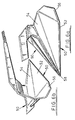
- Figs. 5 and 6 of the drawings depicts an alternative modification of a marine anchor in accordance with the present invention.
- the blades 30 are not curved but consist of 4 flat sections which are interconnected as shown.
- the blades taper towards a single apex 40 in the same way as before and each blade 30 is also dished inwardly (concave) as with the curved blade shown in Figs 1 to 3.
- the shank 42 has a plurality of circular holes 44 machined therein so that the buoyant centre of gravity can be predetermined.
- FIGs 6a and 6b shows an anchor similar to that shown in Figs. 5a and 5b except that each blade of the anchor 50 is formed by 3 plates 52, 54, and 56 interconnected. The plates taper towards a single apex 58 and are dished inwardly as before.
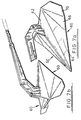
- FIGs. 7a and 7b this shows yet another modification of the marine anchor which has blades 60 made of 4 flat plates interconnected but which are shaped differently to those shown in Figs 5a and 5b and in in Figs, 6a and 6b.
- Each blade 60 consists of 4 flat blades 62, 66 and 68 and 70 which are interconnected as shown which taper to a common apex and each blade 60 is dished inwardly or concave shaped as indicated above.
- the buoyant centre of gravity can be varied, although it is desirable to keep the centre of gravity below the line of pull action A-A in Fig. 1, by the addition of weights, provided by heavy metals such as lead, disposed beneath the ridge joining the blades of the fluke or by the incorporation of buoyant or semibuoyant materials such as air or foam in the shank.
- the strut may be omitted if the blades 20 are sufficiently rigid.
- the blades may be flat or angled as well as curved to define a concave appearance and the anchor may be made by welding the shank 12 to the fluke 14 instead of casting.
- the anchor can be modified to include spring or resilient materials on the shank to prevent permanent deformation to the shank if the direction of pull is changed and also so that the anchor will re-orientate in the new direction of pull without emerging from the seabed.
- an advantage of the embodiments hereinbefore described are that the anchor always lands on the seabed in 3-point contact, so that in response to a pull its after surface causes the rear end of the anchor to rise up causing the apex to penetrate the seabed.
- the sharp single apex can penetrate a variety of seabed surfaces including weed, sea grass, kelp in sand as well as shingle.
- the single point and blade shape facilitate the tip acting as a fulcrum in response to line pull and causes the anchor to become effectively embedded in the seabed.
- the anchor is self-aligning in the direction of pull and roll-stable when being dragged along the seabed.
- the shape of the fluke blades are that on meeting an obstruction the blade area increases in the side opposite to the obstruction and causes the anchor to self steer around the obstruction in the direction of pull.
- the anchor stows in the bow roller so that tension on the pull end of the shank locks the anchor from movement in a seaway with the centre of gravity inboard and release of tension causes the anchor to slide forward on the bow roller such that the centre of gravity is moved outboard of the bow roller in which case the anchor rotates about the stemhead roller and self-launches.
- the unitary construction, cast or fabricated, facilitates safer handling because of the absence of a hinge.
- the shape of the anchor is such that should it bury in a soft seabed with the tail down and point up, pulling on the anchor causes the tail, which is at an angle greater that 65° to the direction of pull, to lift up and cause the apex and tip to penetrate the seabed.
Landscapes
- Chemical & Material Sciences (AREA)
- Engineering & Computer Science (AREA)
- Combustion & Propulsion (AREA)
- Mechanical Engineering (AREA)
- Ocean & Marine Engineering (AREA)
- Piles And Underground Anchors (AREA)
Abstract
Claims (13)
- Ancre monobloc (1) à descente libre du type s'enterrant, comportant une verge (12;42) possédant une extrémité avant (8) apte à être raccordée à un câble principal d'ancre, une aile (14) fixée rigidement à la verge (12), ladite aile possédant essentiellement la forme d'un soc à deux lames, les lames (16;30;60) étant disposées symétriquement de part et d'autre du plan médian (X-X) de la verge (12), les extrémités avant des lames se terminant sous la forme d'une pointe unique (18;58), les extrémités arrière de chaque lame (13;30;60) divergeant vers l'extérieur à partir dudit plan médian (X-X), et chaque lame possédant une forme (20) recourbée d'une manière générale vers l'intérieur, ladite verge (12) et ladite aile (14) étant agencées de manière à définir un centre de gravité d'application de la poussée d'Archimède (c) situé entre la verge (12) et l'aile (14) en avant de la jonction entre la verge et l'aile, de telle sorte que, lorsqu'elle est utilisée, l'ancre tend à s'appliquer sur le fond de la mer selon un contact en trois points, ledit contact en trois points étant établi au moyen de l'extrémité avant (8) de la verge (12), de ladite pointe commune (18;58) et de l'extrémité arrière (21) de l'une des ailes (16).
- Ancre selon la revendication 1, dans laquelle ledit centre de gravité d'application de la poussée d'Archimède (c) est situé du côté d'une ligne sur l'aile, qui s'étend entre l'extrémité avant de la verge (12) et une ligne de largeur maximale de la lame.
- Ancre selon l'une quelconque des revendications 1 ou 2, dans laquelle les lames sont des tôles cintrées.
- Ancre selon l'une quelconque des revendications 1 ou 2, dans laquelle les lames (30;60) sont constituées par une pluralité de surfaces planes ou anguleuses (34,36,38;52,54,56).
- Ancre selon l'une quelconque des revendications précédentes, dans laquelle la position du centre de gravité d'application de la poussée d'Archimède (c) est modifiée par l'incorporation de matériaux flottants ou semi-flottants à l'intérieur de la verge (42) ou bien par élimination de matière de la verge de manière à définir des trous (44) le long de cette dernière.
- Ancre selon l'une quelconque des revendications précédentes, dans laquelle le centre de gravité d'application de la poussée d'Archimède peut être modifié moyennant la mise en place d'un métal lourd au-dessous de la jonction (17) des lames (16).
- Ancre selon l'une quelconque des revendications précédentes, dans laquelle la forme des ailes (14) est telle que, lorsqu'une traction est appliquée à l'extrémité avant (8) de la verge (12) lorsque ladite ancre (10) repose sur le fond de la mer, la pointe (18;58) pénètre dans le fond de la mer et agit en tant que pivot lors d'une poursuite d'une traction ultérieure de sorte que l'aile (14) s'enterre de façon automatique.
- Ancre selon l'une quelconque des revendications précédentes, dans laquelle l'ancre (10) est une pièce moulée monobloc.
- Ancre selon l'une quelconque des revendications 1 à 8, dans laquelle l'ancre (10) peut être formée par soudage de la verge (12) sur l'aile (14) de manière à former une unité monobloc.
- Ancre selon l'une quelconque des revendications précédentes, dans laquelle la verge (12) comprend une partie élastique servant à minimiser la déformation appliquée à la verge (12) dans le cas où une traction est appliquée à cette dernière transversalement à la ligne usuelle d'action.
- Ancre selon l'une quelconque des revendications précédentes, dans laquelle un élément de support (22) est monté entre les extrémités arrière (21) des lames (16), ledit support (22) étant monté entre les surfaces inférieures présentes au niveau de l'extrémité arrière des lames (21).
- Ancre selon l'une quelconque des revendications précédentes, dans laquelle la verge (12) comprend des moyens de raccordement (6) montés sur ladite verge pour la fixation d'un câble rapporteur ou d'un câble traînard.
- Ancre (10) du type s'enterrant, comprenant une verge essentiellement rigide (12), et une aile (14) raccordée rigidement à cette ancre et possédant la forme générale d'un soc à deux lames comportant une extrémité avant pointue (18;58) et sensiblement symétrique par rapport à un plan médian longitudinal (X-X), la surface extérieure recourbée d'une manière générale vers l'intérieur (20) de chaque lame (16) de l'aile (14) s'étendant soit des deux côtés d'une nervure centrale (17) formée par la jonction entre lesdites surfaces extérieures (20), et étant d'une manière générale parallèle à ladite nervure centrale (17) au niveau de la partie d'extrémité avant (21) de l'aile (14) et divergeant en direction d'une partie d'extrémité arrière de l'aile, au niveau de laquelle ladite aile (14) est raccordée à la verge (12) de sorte que ladite surface (20) des lames de l'aile s'étend sensiblement obliquement par rapport à ladite nervure centrale (17) au niveau de ladite partie arrière au moins dans une partie latérale extérieure (21) qui est distante latéralement de la nervure centrale (17) de sorte que l'aile présente un élément de surface important tourné d'une manière générale dans la direction de la traction appliquée à l'ancre lors de son utilisation lorsque ladite ancre a pénétré dans le fond de la mer et s'est orientée d'elle-même sur la direction de la traction, ladite verge (12) et ladite aile (14) étant agencées de manière à définir un centre de gravité d'application de la poussée d'Archimède (c) disposé entre la verge et l'aile, en avant de la jonction entre la verge et l'aile, de sorte que, lorsqu'elle est utilisée, l'ancre tend à s'appliquer sur le fond de la mer selon un contact en trois points, ledit contact en trois points étant établi au moyen de l'extrémité avant (8) de la verge (12), ladite extrémité avant pointue (18;58) de l'aile et une extrémité arrière (21) de l'une des ailes (16).
Applications Claiming Priority (3)
| Application Number | Priority Date | Filing Date | Title |
|---|---|---|---|
| GB888808373A GB8808373D0 (en) | 1988-04-09 | 1988-04-09 | Marine anchor |
| GB8808373 | 1988-04-09 | ||
| PCT/GB1989/000339 WO1989009722A1 (fr) | 1988-04-09 | 1989-04-03 | Ancre marine |
Publications (3)
| Publication Number | Publication Date |
|---|---|
| EP0425497A1 EP0425497A1 (fr) | 1991-05-08 |
| EP0425497B1 EP0425497B1 (fr) | 1993-01-27 |
| EP0425497B2 true EP0425497B2 (fr) | 1997-10-15 |
Family
ID=10634895
Family Applications (1)
| Application Number | Title | Priority Date | Filing Date |
|---|---|---|---|
| EP89904584A Expired - Lifetime EP0425497B2 (fr) | 1988-04-09 | 1989-04-03 | Ancre marine |
Country Status (7)
| Country | Link |
|---|---|
| US (1) | US5138967B1 (fr) |
| EP (1) | EP0425497B2 (fr) |
| AU (1) | AU628047B2 (fr) |
| DE (1) | DE68904653T3 (fr) |
| GB (1) | GB8808373D0 (fr) |
| NZ (1) | NZ228656A (fr) |
| WO (1) | WO1989009722A1 (fr) |
Families Citing this family (18)
| Publication number | Priority date | Publication date | Assignee | Title |
|---|---|---|---|---|
| GB9110950D0 (en) * | 1991-05-21 | 1991-07-10 | Brupat Ltd | Improved marine anchor |
| GB9125241D0 (en) * | 1991-11-27 | 1992-01-29 | Brupat Ltd | Drag embedment marine anchor |
| US5188055A (en) * | 1992-01-08 | 1993-02-23 | Kershner Gary P | Adjustable boat anchor |
| USD375717S (en) | 1994-08-10 | 1996-11-19 | Dick Ian G | Anchor |
| USD403394S (en) | 1996-06-13 | 1998-12-29 | Top-Me Inc. | Hook for crab fish and lobster traps |
| US5855181A (en) * | 1997-02-14 | 1999-01-05 | Oxford; Sefton M.D. | Fixed shank plow anchor |
| EP1012034A1 (fr) * | 1997-02-26 | 2000-06-28 | Desire Dominique Hoareau | Ancre soc amelioree |
| US6148758A (en) * | 1998-02-04 | 2000-11-21 | Electromechanical Research Laboratories, Inc. | Boat anchor |
| US6041731A (en) * | 1999-04-27 | 2000-03-28 | Willis; John A. | Self-righting plow anchor with float |
| EP1173357B1 (fr) * | 1999-04-27 | 2004-08-11 | John A. Willis | Ancre flotteur relevage automatique |
| EP1500583B1 (fr) * | 2000-04-27 | 2011-04-20 | Stevlos B.V. | Ancre avec patte comportant une surface supérieure comprenant des plans latéraux inclinés vers le bas |
| US6332423B1 (en) | 2001-02-09 | 2001-12-25 | Kingston Anchors Limited | Marine anchor |
| US6390011B1 (en) * | 2001-09-07 | 2002-05-21 | Jack Goodman | Smart anchor |
| USD489669S1 (en) | 2002-10-21 | 2004-05-11 | Yukitoshi Sugiyama | Anchor |
| EP1462357B1 (fr) * | 2003-03-27 | 2007-09-12 | Alain Poiraud | Ancre asymétrique sans ballast |
| USD556666S1 (en) * | 2006-02-16 | 2007-12-04 | Manson Anchors Limited | Anchor |
| WO2008116272A1 (fr) * | 2007-03-27 | 2008-10-02 | Rex William Francis | Ancre améliorée |
| NL2002086C (nl) * | 2008-10-10 | 2010-04-13 | Stevlos Bv | Anker met meetkoppeling. |
Family Cites Families (10)
| Publication number | Priority date | Publication date | Assignee | Title |
|---|---|---|---|---|
| DE225678C (fr) * | ||||
| DE617814C (de) * | 1933-03-21 | Geoffrey Ingram Taylor | Anker | |
| US1983481A (en) * | 1934-01-15 | 1934-12-04 | Chris V Larsen | Anchor |
| US2161906A (en) * | 1938-10-08 | 1939-06-13 | Carlton W Filby | Marine anchor |
| US2948249A (en) * | 1956-10-22 | 1960-08-09 | Gesner | Single fluke anchor |
| NL6802686A (fr) * | 1968-02-26 | 1969-08-28 | ||
| US3759212A (en) * | 1972-02-02 | 1973-09-18 | D Cluett | Anchor |
| FR2366987A1 (fr) * | 1976-10-06 | 1978-05-05 | Colin Armand | Systeme d'ancres modulaire |
| GB2035242B (en) * | 1978-11-17 | 1983-04-13 | Smith R | Anchor |
| US4602588A (en) * | 1984-09-14 | 1986-07-29 | Maclean John A | Anchor |
-
1988
- 1988-04-09 GB GB888808373A patent/GB8808373D0/en active Pending
-
1989
- 1989-04-03 EP EP89904584A patent/EP0425497B2/fr not_active Expired - Lifetime
- 1989-04-03 WO PCT/GB1989/000339 patent/WO1989009722A1/fr not_active Ceased
- 1989-04-03 AU AU34150/89A patent/AU628047B2/en not_active Expired
- 1989-04-03 DE DE68904653T patent/DE68904653T3/de not_active Expired - Lifetime
- 1989-04-07 NZ NZ228656A patent/NZ228656A/en unknown
-
1990
- 1990-11-01 US US07582939 patent/US5138967B1/en not_active Expired - Lifetime
Also Published As
| Publication number | Publication date |
|---|---|
| WO1989009722A1 (fr) | 1989-10-19 |
| DE68904653D1 (de) | 1993-03-11 |
| AU628047B2 (en) | 1992-09-10 |
| DE68904653T3 (de) | 1998-05-07 |
| US5138967B1 (en) | 1997-01-14 |
| NZ228656A (en) | 1990-12-21 |
| AU3415089A (en) | 1989-11-03 |
| EP0425497A1 (fr) | 1991-05-08 |
| US5138967A (en) | 1992-08-18 |
| DE68904653T2 (de) | 1993-06-24 |
| EP0425497B1 (fr) | 1993-01-27 |
| GB8808373D0 (en) | 1988-05-11 |
Similar Documents
| Publication | Publication Date | Title |
|---|---|---|
| EP0425497B2 (fr) | Ancre marine | |
| EP2129573B1 (fr) | Ancre améliorée | |
| US4706595A (en) | Anchor | |
| EP0020152B1 (fr) | Verge d'ancre | |
| US5353732A (en) | Anchor for heavy loads | |
| US5970902A (en) | Anchors | |
| US4802434A (en) | Anchor | |
| GB2035242A (en) | Anchor | |
| US5934219A (en) | Spearhead anchor | |
| US4459934A (en) | Anchor | |
| US6332423B1 (en) | Marine anchor | |
| US3373712A (en) | Anchor having pivotable flukes | |
| US4397257A (en) | Sea anchor in particular for large ships | |
| US4154186A (en) | Boat anchor | |
| US4708086A (en) | Boat anchor | |
| CA1063883A (fr) | Ancre | |
| US3382835A (en) | Marine anchor | |
| US4704982A (en) | Anchor arranged for lowering along an inclined plane | |
| CN212022906U (zh) | 新型泊船锚 | |
| US3902446A (en) | Anchor | |
| US4545318A (en) | Anchor construction | |
| AU734943B2 (en) | Improvements in anchors | |
| US5067430A (en) | Anchor with axis control bar | |
| GB2051717A (en) | Stockless anchor | |
| US4418635A (en) | Single-fluke anchor |
Legal Events
| Date | Code | Title | Description |
|---|---|---|---|
| PUAI | Public reference made under article 153(3) epc to a published international application that has entered the european phase |
Free format text: ORIGINAL CODE: 0009012 |
|
| 17P | Request for examination filed |
Effective date: 19901009 |
|
| AK | Designated contracting states |
Kind code of ref document: A1 Designated state(s): BE CH DE FR GB IT LI NL SE |
|
| 17Q | First examination report despatched |
Effective date: 19920430 |
|
| GRAA | (expected) grant |
Free format text: ORIGINAL CODE: 0009210 |
|
| AK | Designated contracting states |
Kind code of ref document: B1 Designated state(s): BE CH DE FR GB IT LI NL SE |
|
| PG25 | Lapsed in a contracting state [announced via postgrant information from national office to epo] |
Ref country code: CH Effective date: 19930127 Ref country code: SE Effective date: 19930127 Ref country code: LI Effective date: 19930127 |
|
| ITF | It: translation for a ep patent filed | ||
| REF | Corresponds to: |
Ref document number: 68904653 Country of ref document: DE Date of ref document: 19930311 |
|
| ET | Fr: translation filed | ||
| REG | Reference to a national code |
Ref country code: CH Ref legal event code: PL |
|
| PLBI | Opposition filed |
Free format text: ORIGINAL CODE: 0009260 |
|
| 26 | Opposition filed |
Opponent name: BRUPAT LIMITED Effective date: 19931025 |
|
| NLR1 | Nl: opposition has been filed with the epo |
Opponent name: BRUPAT LIMITED. |
|
| PLBQ | Unpublished change to opponent data |
Free format text: ORIGINAL CODE: EPIDOS OPPO |
|
| PLAB | Opposition data, opponent's data or that of the opponent's representative modified |
Free format text: ORIGINAL CODE: 0009299OPPO |
|
| R26 | Opposition filed (corrected) |
Opponent name: BRUPAT LIMITED Effective date: 19931025 |
|
| APAC | Appeal dossier modified |
Free format text: ORIGINAL CODE: EPIDOS NOAPO |
|
| PLAW | Interlocutory decision in opposition |
Free format text: ORIGINAL CODE: EPIDOS IDOP |
|
| NLR1 | Nl: opposition has been filed with the epo |
Opponent name: BRUPAT LIMITED |
|
| PUAH | Patent maintained in amended form |
Free format text: ORIGINAL CODE: 0009272 |
|
| STAA | Information on the status of an ep patent application or granted ep patent |
Free format text: STATUS: PATENT MAINTAINED AS AMENDED |
|
| 27A | Patent maintained in amended form |
Effective date: 19971015 |
|
| AK | Designated contracting states |
Kind code of ref document: B2 Designated state(s): BE CH DE FR GB IT LI NL SE |
|
| REG | Reference to a national code |
Ref country code: CH Ref legal event code: AEN Free format text: AUFRECHTERHALTUNG DES PATENTES IN GEAENDERTER FORM |
|
| NLR2 | Nl: decision of opposition | ||
| ITF | It: translation for a ep patent filed | ||
| ET3 | Fr: translation filed ** decision concerning opposition | ||
| NLR3 | Nl: receipt of modified translations in the netherlands language after an opposition procedure | ||
| NLR4 | Nl: receipt of corrected translation in the netherlands language at the initiative of the proprietor of the patent | ||
| REG | Reference to a national code |
Ref country code: GB Ref legal event code: IF02 |
|
| PGFP | Annual fee paid to national office [announced via postgrant information from national office to epo] |
Ref country code: GB Payment date: 20040901 Year of fee payment: 16 |
|
| PG25 | Lapsed in a contracting state [announced via postgrant information from national office to epo] |
Ref country code: GB Free format text: LAPSE BECAUSE OF NON-PAYMENT OF DUE FEES Effective date: 20050403 |
|
| APAH | Appeal reference modified |
Free format text: ORIGINAL CODE: EPIDOSCREFNO |
|
| GBPC | Gb: european patent ceased through non-payment of renewal fee |
Effective date: 20050403 |
|
| PLAB | Opposition data, opponent's data or that of the opponent's representative modified |
Free format text: ORIGINAL CODE: 0009299OPPO |
|
| PGFP | Annual fee paid to national office [announced via postgrant information from national office to epo] |
Ref country code: FR Payment date: 20080312 Year of fee payment: 20 Ref country code: DE Payment date: 20080411 Year of fee payment: 20 |
|
| PGFP | Annual fee paid to national office [announced via postgrant information from national office to epo] |
Ref country code: BE Payment date: 20080616 Year of fee payment: 20 Ref country code: IT Payment date: 20080428 Year of fee payment: 20 |
|
| PGFP | Annual fee paid to national office [announced via postgrant information from national office to epo] |
Ref country code: NL Payment date: 20080303 Year of fee payment: 20 |
|
| BE20 | Be: patent expired |
Owner name: *SIMPSON-LAWRENCE LTD Effective date: 20090403 |
|
| PG25 | Lapsed in a contracting state [announced via postgrant information from national office to epo] |
Ref country code: NL Free format text: LAPSE BECAUSE OF EXPIRATION OF PROTECTION Effective date: 20090403 |
|
| NLV7 | Nl: ceased due to reaching the maximum lifetime of a patent |
Effective date: 20090403 |