EP0425807B1 - Umkehrkreuzungsschalter mit verteilter Steuerung - Google Patents
Umkehrkreuzungsschalter mit verteilter Steuerung Download PDFInfo
- Publication number
- EP0425807B1 EP0425807B1 EP90118071A EP90118071A EP0425807B1 EP 0425807 B1 EP0425807 B1 EP 0425807B1 EP 90118071 A EP90118071 A EP 90118071A EP 90118071 A EP90118071 A EP 90118071A EP 0425807 B1 EP0425807 B1 EP 0425807B1
- Authority
- EP
- European Patent Office
- Prior art keywords
- controllers
- controller
- port
- ports
- interconnection
- Prior art date
- Legal status (The legal status is an assumption and is not a legal conclusion. Google has not performed a legal analysis and makes no representation as to the accuracy of the status listed.)
- Expired - Lifetime
Links
- 238000000034 method Methods 0.000 claims description 34
- 230000008569 process Effects 0.000 claims description 5
- 230000004044 response Effects 0.000 claims description 2
- 238000005192 partition Methods 0.000 description 40
- 230000000903 blocking effect Effects 0.000 description 25
- 239000011159 matrix material Substances 0.000 description 17
- 238000000638 solvent extraction Methods 0.000 description 11
- 238000009826 distribution Methods 0.000 description 8
- 230000006870 function Effects 0.000 description 8
- 238000013461 design Methods 0.000 description 6
- 238000012360 testing method Methods 0.000 description 6
- 238000012545 processing Methods 0.000 description 5
- 238000010586 diagram Methods 0.000 description 4
- 230000006872 improvement Effects 0.000 description 4
- 238000013459 approach Methods 0.000 description 2
- 238000001514 detection method Methods 0.000 description 2
- 230000009471 action Effects 0.000 description 1
- 230000008901 benefit Effects 0.000 description 1
- 230000015556 catabolic process Effects 0.000 description 1
- 238000004891 communication Methods 0.000 description 1
- 230000001186 cumulative effect Effects 0.000 description 1
- 238000006731 degradation reaction Methods 0.000 description 1
- 230000008030 elimination Effects 0.000 description 1
- 238000003379 elimination reaction Methods 0.000 description 1
- 230000005012 migration Effects 0.000 description 1
- 238000013508 migration Methods 0.000 description 1
- 238000012986 modification Methods 0.000 description 1
- 230000004048 modification Effects 0.000 description 1
- 238000012544 monitoring process Methods 0.000 description 1
- 238000009828 non-uniform distribution Methods 0.000 description 1
- 230000008707 rearrangement Effects 0.000 description 1
- 230000010076 replication Effects 0.000 description 1
- 230000008672 reprogramming Effects 0.000 description 1
Images



Classifications
-
- H—ELECTRICITY
- H04—ELECTRIC COMMUNICATION TECHNIQUE
- H04Q—SELECTING
- H04Q3/00—Selecting arrangements
- H04Q3/42—Circuit arrangements for indirect selecting controlled by common circuits, e.g. register controller, marker
- H04Q3/52—Circuit arrangements for indirect selecting controlled by common circuits, e.g. register controller, marker using static devices in switching stages, e.g. electronic switching arrangements
- H04Q3/521—Circuit arrangements for indirect selecting controlled by common circuits, e.g. register controller, marker using static devices in switching stages, e.g. electronic switching arrangements using semiconductors in the switching stages
Definitions
- This invention relates to a one-sided crosspoint switch for producing electrical interconnections among a plurality of ports in response to interconnecting requests, including a plurality of internal buses and a plurality of crosspoint switching elements, each one of said switching elements being connected to one of said ports and to one of said internal buses and said switching elements being set by a controller for selectively interconnecting said connected port to said connected internal bus, and further including a port connection table to record which ports are presently busy.
- Crosspoint switches are used in the telephone and computer industry for switching data among communication lines.
- One type of crosspoint switch is the one-sided crosspoint switch described by Christos Georgiou in U.S. Patent 4,635,250.
- Figure 1 illustrates a prior art one-sided crosspoint switch.
- a set of data lines 101-116 is intersected by a set of internal buses 201-208, which together form a switching matrix.
- a crosspoint switching element (or "crosspoint") is located at each point of intersection.
- Each data line also is connected to a switch port (or "port”) via a port adapter.
- a connection between two data lines is set up by selecting one of the internal buses and then turning on the crosspoint switching elements at the points of intersection of the selected bus with each of the data lines. For example, a connection between data lines 104 and 112 (and therefore between the port connected to data line 104 and the port connected to data line 112) can be achieved by turning on switching elements 10 and 12, thereby making use of the bus 206.
- the same connection can be set up through any of the other internal buses, provided that it is not already in use for interconnecting a different pair of ports. For allowing simultaneous pairwise connections between all of the ports, the number of buses should be at least half the total number of ports.
- Such a switching system is called a non-blocking switch because it allows no connection to be blocked as a result of other connections.
- the 16-port switch in Figure 1 is thus non-blocking because of the presence of eight internal buses.
- a one-sided crosspoint matrix generally is constructed from one or more switching chips. If the number of ports in the system is small, the entire matrix can be implemented by means of a single chip. However, if the number of ports is large, it is necessary to partition the matrix into rectangular blocks so that each block can be implemented by a switching chip of moderate size. Each rectangular block or partition actually is a smaller one-sided crosspoint switch by itself. In such a case, the one-sided crosspoint switch can be thought of as consisting of a plurality of component one-sided crosspoint switches, typically arranged in rows and columns. For illustration, the switching matrix in Figure 1 has been shown as consisting of four switching chips, each chip having eight horizontal data lines and four vertical internal buses.
- a major advantage of one-sided crosspoint switches is the flexibility in allowing any of the internal buses to make a connection as long as the selected bus is not in use for another connection. This allows the system to operate in the presence of faulty buses.
- a faulty bus reduces the capacity by reducing the number of connections that can be provided simultaneously, but no ports are taken out of service as a result of the elimination of a faulty bus.
- Controller 14 receives requests for connection and disconnection from the port adapters over a port adapter bus 18 and activates or deactivates proper crosspoints in the matrix. When the combined rate at which such connections and disconnections are requested is high, a fast controller is required to handle these requests. This is frequently the case when the switch is used to interconnect computers in a multiprocessor system where the lifetime of a connection is very short.
- a controller for control of one-sided crosspoint networks is described in U.S. Patent 4,630,045 issued to Christos Georgiou. This controller achieves its speed by means of pipelining, that is by allowing one processing-step of a request to be executed simultaneously with another step of a second request.
- the present invention overcomes these two problems in part by distributing the control of the switching matrix among multiple controllers instead of using a single controller.
- An object of the present invention is to improve the speed of large one-sided crosspoint switches.
- Another object is to increase the number of connections which can be established or broken by a one-sided crosspoint switch beyond one per machine cycle.
- Still another object is to provide a single-sided cross point switch which is more reliable.
- distribution of the control of a single-sided crosspoint switching matrix takes place by using multiple controllers instead of a single controller.
- the controllers are identical and operate in parallel, each setting up connections in a variably assigned region of the switching matrix.
- Requests for connection or disconnection from the ports are distributed among the controllers using a distribution scheme such that each request is serviced by one and only one of the controllers.
- the distribution of requests is altered such that each request is routed to a fault-free controller.
- the switch can operate so long as one of the controllers is fully functional.
- the number of controllers is flexible and can be chosen to optimize various parameters such as cost, performance, and reliability.
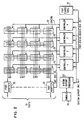
- FIG. 2 A block diagram of a preferred embodiment of the invention is shown in Fig. 2.
- a one-sided crosspoint switch having 16 ports is implemented with 16 individual chips.
- the chips are arranged in a rectangular matrix with 4 horizontal rows and 4 vertical columns.
- Each switching chip embodies a switching matrix consisting of 4 horizontal data lines and 4 vertical internal buses.
- the number of vertical buses in the switching chips can be identical or they can vary in number for each chip-column.
- the number of internal buses for each chip-column depends on a number of design factors such as the specific scheme used for routing requests from ports among the controllers, and the degree of allowable blocking. Criteria for determination of the number of internal buses are described later.
- the total number of internal vertical buses in the system is the sum of all of the individual sets of internal buses.
- the example shown in Fig. 2 has four buses in the first chip-column, three in each of the two middle chip-columns, and two in the last chip-column, resulting in a total of 12 internal buses. Note that the total number of vertical buses needed to achieve non-blocking operation would only be 8 (for 16 ports) if a single controller were used to set up the switching matrix.
- the extra 4 buses shown in Fig. 2 represent an overhead caused by the distribution of control. This overhead depends on many factors, such as the number of controllers, the specific scheme used for routing requests from ports among the controllers, and the degree of allowable blocking. The exact nature of this overhead is described in more detail later in connection with the description of methods used for distribution of requests among the controllers.
- each column of chips is controlled by an individual controller.
- the choice of one controller per chip-column is simply for convenience.
- the number of controllers can be chosen to be any number so long as there is at least one internal bus for each controller.
- the number of controllers, the number of internal buses and the distribution of the internal buses among the controllers is chosen to meet desired design objectives on cost, performance, and reliability. In the following description it is assumed, however, that the number of controllers is equal to the number of chip-columns.
- Requests for connection or disconnection originate at the port adapters 20 and are conveyed to the controllers via the port bus 18.
- a request typically consists of the addresses of the source and destination ports involved, and the action to be performed, that is, connection or disconnection.
- Each of the controllers is programmed by the system support processor 22 to respond to a certain set of source and destination addresses ("port pairs") in the connection/disconnection request.
- a request from a port reaches all the controllers via the port bus 18, but is recognized by only the particular controller which has been programmed to process a request for connection or disconnection of that particular port pair.
- the status of each of the ports that is, whether it is free or connected, is kept in a port status table 24, shared by all the controllers.
- the controllers access the port status table 24 via the port status access bus 26.
- the controllers are connected to the system support processor 22 by means of a system support bus 28.
- the system support processor 22 is responsible for programming the controllers during system initialization so that each controller responds to the requests from a unique set of port pairs. It is also responsible for detection of controller failures and the reprogramming the the remaining fault-free controllers so as to distribute the function of the faulty controller among the remaining ones.
- An operator console 30 attached to the system support processor 22 allows configuration and monitoring of the system.
- Fig. 3 shows one of the controllers of Fig. 2 in more detail.
- the controller is capable of connecting any two ports of the system, but it can use only one of the vertical buses which it controls.
- the controller sets up a connection between two ports by choosing a free bus (that is, a bus that is not in use for implementing any other connection at that time) and turning on the two crosspoints at the intersection of the designated bus and the two data lines connected to the ports. A disconnection is performed by turning them off.
- the controller addresses the individual crosspoints by means of row and column address lines.
- the row address selects one of the data lines and the column address selects one of the individual buses.
- These two sets of address lines specify a crosspoint, which can then be turned on or off by means of a set of control lines 32, which are schematically shown only as a single line.
- Each controller is programmed to recognize requests for connection or disconnection between only certain port pairs. This is achieved by means of a port address lookup table 34 in the controller.
- the port address lookup table is a random-access-memory (RAM) addressed by the source and destination addresses in a request placed on the port bus 18. If the total number of ports is 256, for example, a port address would be 8 bits long.
- the port address lookup table in such case might be implemented with a random-access-memory having a capacity of 65,536 bits, organized as 65536 words times 1 bit. In the 16-port example shown in Fig. 2, the memory size is 256 times 1.
- a '1" might be stored at a port pair location in the port address lookup table, for example, if the corresponding pair of source and destination addresses is to be recognized by the controller and a '0' stored otherwise.
- the port address lookup table 34 is loaded by the system support processor 22 via the service bus 28. During system initialization, the system support processor determines which port pairs will be serviced by a particular controller and loads the port address lookup table accordingly. Similarly, if the support processor determines that a certain controller is faulty, it modifies the port address lookup tables of the controllers so that the port pairs previously assigned to the faulty controller are redistributed among the fault-free controllers.
- the processing controller To process a connection request, the processing controller must first determine the status of the destination port.
- the destination port may already be connected, either as a source port or as a destination port.
- the port status table 24 is used to record the status of each port, that is free or connected.
- the port status table is set up as a multiword random-access memory in which addresses correspond to the ports. Each location in the memory stores the status of the corresponding port.
- the status information consists of, at a minimum, one bit to indicate whether the corresponding port is free or connected.
- the port status table 24 is shared by all the controllers.
- the controllers access the port status table via the port status access bus 26.
- the bus allows exclusive access to the table memory, one controller at a time.
- To make a connection between a source port A and a destination port B it is necessary for the processing controller to check the status of both A and B in the port status table. If both are free, the controller then updates their status in the port status table as "connected".
- These two read and update operations should be implemented as a single indivisible operation, that is a second controller should not be allowed access to the port status table between these operations. This is achieved by allowing a controller to hold the bus 26 until the read and update operations are completed.
- the port status access bus 26 can be shared among the various controllers.
- a simple method is time-division-multiplexing, where the controllers access the bus in sequence, each occupying the bus for a fixed time-slot. Note that each time-slot consists of multiple bus-cycles to implement the read/update operations.
- a controller can request the bus asynchronously when needed, and is allowed access if the bus is not in use. Simultaneous requests from more than one controller may be resolved through an arbitration scheme such as a round-robin.
- a connection request originating at a port adapter is processed as follows. Let A be the originating port and B be the requested destination port. The request is broadcast on the port bus and is received by all the controllers. The pair of port addresses A, B in the request are used by each controller to address its port-address lookup table. Only one of the port-address lookup tables has a '1' stored at this location. This controller then proceeds to process the request. The remaining controllers ignore the request.
- the processing controller accesses the port status table to determine if ports A and B are free and if so, updates their status to "connected".
- the controller then chooses a vertical internal bus under its control for making the connection. Any unused bus under its control can be chosen for the connection as long as it is not being used at the present time for making another connection. This selection is accomplished with the aid of a bus status register 36.
- This register contains one bit for each bus under the control of that controller to indicate its status, that is free or allocated.
- a '0' may be stored for every bus that is in use, for example, and a '1" for every available bus.
- a priority encoder uses the output of this register to generate the address of a free bus.
- controller turns on the two crosspoints at the intersection of the selected bus and the data lines connected to ports A and B, thereby making the connection.
- control logic 38 which provide the necessary control signals to the circuit elements.
- the controller finds the status of either A or B, as connected in the port status table, it rejects the request from the port.
- the controller informs the originating port adapter via the port bus that the connection cannot be made.
- the port adapter then informs the requesting device connected to that port by sending a special 'reject' message.
- a similar reject message is sent if the controller finds all the buses in its column in use. This represents a blocking condition. Such blocking can be eliminated if a sufficient number of buses are provided for each controller to handle the maximum number of simultaneous connections routed to that controller.
- bus status register which records the status of each vertical bus under the control of a particular controller is local to that controller, because each controller has exclusive use of those buses.
- the port status table which records the status of the ports, on the other hand, is shared by all the controllers.
- a disconnect request is processed in a similar manner.
- the request is recognized by the same controller which processed the connection request, which then releases the bus used for the connection by turning off the corresponding crosspoints.
- the status of the bus is marked as free in the bus status register.
- the port status table is also updated to reflect the "free" status of the two ports involved.
- One of the merits of the invention is its fault-tolerance, in particular that of a controller.
- the failure of a controller affects all the requests that the controller had been originally set up to recognize.
- Ability to tolerate a controller failure requires two steps: (i) detection of the failure and (ii) re-programming the fault-free controllers to migrate the function of the faulty controller to the fault-free ones.
- the failure of a controller can be detected in many ways. One approach is to make them self-testing, which simply means that each controller is designed to test itself concurrently during its normal operation and report any errors to the system support processor. The art of designing such self-testing circuits is described in the following articles and the references therein, which are hereby incorporated by reference.
- the system support processor alternatively could be designed to test the individual controllers periodically.
- the system support processor finds a controller faulty, by one of the above means, it distributes the function of the faulty controller among the remaining ones. That is, the requests initially assigned to the faulty controller are now distributed among the fault-free ones. This may be achieved by updating the port address lookup tables in the fault-free controllers in such a way that each pair of source-destination addresses (port pairs) formerly recognized by the faulty controller will be recognized thereafter by one of them.
- a controller failure also makes the corresponding internal buses unusable. This may introduce some blocking, since there may not be enough buses serving the remaining controllers to handle all the requests routed to them. However, all the ports remain in service. Alternatively, extra buses could be provided in the design to take up the additional load when a controller fails.
- the invention can be used to construct a highly reliable switching system.
- the port status table which is shared by all the controllers, can be protected by means of error-correcting codes to prevent it from being a single-point-of-failure.
- the port bus can be duplicated for reliability; this also improves performance because requests can now be routed to controllers along two separate paths.
- each of the m controllers is set up to recognize certain requests based on the addresses of the source and destination ports. If there is a total of N ports in the system, and each of these ports can make a request to connect to any one of the ports excluding itself, then a total of N(N-1) distinct requests are possible, each involving a distinct pair of source and destination port addresses. These N(N-1) different possible connection requests (port pairs) must be distributed among the controllers such that each connection request is recognized by one and only one of the controllers.
- Distribution of the possible port pairs among the individual controllers requires some kind of specific algorithm or scheme to determine the assignment of the port pairs to the controllers.
- the assignment computed by the algorithm is then used by the system support processor to set up the port address lookup tables of the individual controllers. In the following criteria are discussed for choosing such assignments and specific methods of assignment are described.
- connection between two ports say A and B
- one of them is the requesting port (or source port) and the other is the destination port.
- Such a connection can be requested either by port A or port B, depending on which is the source port. It is possible that the request for connection originated at port A and the request for disconnection at port B (or vice-versa).
- a request involving two ports should therefore be processed by the same controller, independent of the originating port. That is, the pair of ports A, B (where A is the source and B the destination) is treated in the same way as the pair B, A for the sake of determining the processing controller.
- a method of distributing the requests among the controllers is therefore achieved by assigning each pair of ports A, B to a controller without distinguishing the order of appearance of A and B in the pair.
- Each point in Fig. 4 represents a pair of ports and there is a total of N(N-1)/2 points (120 in Fig. 4).
- a request involving ports 1 and 4 is represented by a point on the grid at the intersection of the first horizontal line and the fourth vertical line, and is shown as (1,4). It can be seen that the points form a triangular region. There are exactly (N-1) points along the lower edge of the triangle and (N-1) points along the right edge.
- the problem of distributing the requests among the controllers can now be visualized as assigning each point in Fig. 4 to one of the controllers.
- the partitioning scheme will be described first with two controllers.
- the basic idea is to divide the triangular shape in Fig. 4 into two regions of approximately equal area by a horizontal line.
- Fig. 5 shows this partitioning for a 16-port switch.
- the horizontal line divides the 120 points into two parts.
- the upper partition has a triangular shape and has 55 points and the lower one has 65 points. Note that it is impossible in this case to partition the triangular region into two parts by a horizontal line such that the number of points in each half is exactly identical. The difference in their size would depend on the number of ports N.
- the points in each partition are then assigned to the corresponding controller.
- the maximum number of simultaneous connections possible for each of the partitions in Fig. 5 is 5. Therefore a total of 10 buses are needed for both the partitions to be non-blocking.
- the basic idea is to partition the triangle of N(N-1)/2 points into two parts such that the upper part, by itself, forms a triangular region.
- the partitioning is such that the difference in the number of points in the two parts is a minimum.
- the maximum number of simultaneous connections possible in the upper partition is half its height.
- the maximum number of simultaneous connections possible in the lower partition is its height. Therefore the total number of buses needed with this partitioning method is 0.646 N . Note that this represents an overhead of 30 percent over the single-controller case.
- 0.646N 10.336; choosing the largest integer value of 10.336 gives 10, the same as observed in the previous paragraph.
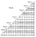
- Fig. 6 illustrates the same partitioning method for a 16-port switch with 4 controllers.
- the number of points in the partitions are 28, 27, 36, and 29, respectively from top to bottom.
- the number of buses needed for non-blocking operation of the individual partitions are 4, 3, 3, and 2, respectively, resulting in a total of 12 buses.
- the maximum number of vertical buses needed for any controller is N/M (4 in the example of Fig. 8) for each of the partitions 2 through M, and N/M-1 for the first partition. Therefore, the total number of buses needed for non-blocking operation can be as large as N-1 with this assignment.
- each controller is assigned exactly the same number of points. Therefore, the load is evenly balanced among the controllers on the average.
- N is large in comparison to M, as is the case in practice, slight non-uniformities among the size of the partitions may not affect the performance significantly.
- the partitions in Fig. 7 have a maximum difference of 1.6 percent in the number of points they contain. Therefore, the first scheme is preferable for most cases because of the lower overhead in the number of buses.
- Reconfiguration without disruption of fault-free controllers This is the preferred method of operation.
- the function of the faulty controller is distributed among the fault-free ones without causing a disruption of service.
- the only connections affected are the connections in the failed partition.
- the port pairs assigned to fault-free controllers are not modified.
- the points assigned to the faulty controller are simply distributed among the fault-free ones.
- a method is required to distribute the port-pairs in the faulty partition among the fault-free ones.
- the new assignment would depend on the initial assignment used. Again, any reassignment would work correctly if every port-pair in the failed partition is assigned to one of the fault-free controllers and no port-pair is assigned to more than one controller.
- the preferred embodiment should satisfy the following, the same properties desired of the initial assignment.
- the first set contains 10 points, the second 11, and the third 7.
- Set 1 can now be assigned to controller 2, set 2 to controller 3, and set 3 to controller 4.
- the reconfiguration is performed by the system support processor, which keeps track of the current assignment of the port pairs among the individual controllers. A subsequent failure can be handled in the same manner. In the worst case, a single fault-free controller remains, with all the N(N-1)/2 pairs assigned to it.
- each controller was assigned approximately the same number of distinct port pairs. This results in equal loading of the controllers on the average if the request pattern is uniform, that is each port pair appears with almost equal probability. However, if the request pattern is skewed, that is certain port pairs occur more frequently compared to others, then load balance can be achieved by resorting to a non-uniform distribution of port pairs among the controllers. Each controller could be assigned an unequal number of port pairs such that the cumulative probability of appearance of all the port pairs assigned to each controller is approximately identical.
- Distributed control causes an overhead in terms of the number of buses needed if non-blocking operation of the system is desired.
Landscapes
- Engineering & Computer Science (AREA)
- Computer Networks & Wireless Communication (AREA)
- Multi Processors (AREA)
- Data Exchanges In Wide-Area Networks (AREA)
- Small-Scale Networks (AREA)
Claims (7)
- Umkehrkreuzungsschalter Herstellen elektrischer Verbindungen zwischen einer Vielzahl von Anschlüssen als Reaktion auf Verbindungsanforderungen, der eine Vielzahl von internen Bussen und eine Vielzahl von Kreuzungsschaltelementen umfaßt, von denen jedes der Schaltelemente mit einem der Anschlüsse und mit einem der internen Busse verbunden ist und die Schaltelemente durch eine Steuerung eingestellt werden, damit sie wahlweise den verbundenen Anschluß mit dem verbundenen internen Bus untereinander verbinden, und der weiterhin eine Anschlußverbindungstabelle umfaßt, um aufzuzeichnen, welche Anschlüsse gegenwärtig besetzt sind,
dadurch gekennzeichnet, daß der Kreuzungsschalter umfaßt:
eine Vielzahl von Steuerungen (1 bis 4), von denen jede diejenigen der Kreuzungsschaltelemente steuert, die mit einer eindeutigen Gruppe interner Busse verbunden sind,
jede unterschiedliche Verbindungsmöglichkeit zwischen einem beliebigen Paar der Anschlüsse einer der Steuerungen variabel zugeordnet wird,
Tabellenmittel (24) über den Anschlußstatus, die auf die Steuerungen (1 bis 4) ansprechen, um den Status der Anschlüsse zu speichern, wenn sie entweder mit einem anderen der Anschlüsse verbunden oder getrennt sind,
Mittel (34) innerhalb jeder der Steuerungen (1 bis 4), um Verbindungsanforderungen zu empfangen und eine Verbindungsanforderung zu erkennen, die einer Verbindungsmöglichkeit entspricht, die einer jeden Steuerung zugeordnet ist,
Mittel (38) innerhalb einer jeden Steuerung, die auf das Erkennen einer Verbindungsanforderung durch das Erkennungsmittel ansprechen, um auf das Anschlußstatustabellenmittel (24) zuzugreifen, um zu bestimmen, ob die Anschlüsse verfügbar sind, die zur Realisierung der erkannten Verbindungsanforderung gebraucht werden, und um zu bestimmen, ob mindestens einer der durch die jeweilige Steuerung gesteuerten internen Busse verfügbar ist, und
Mittel (36) innerhalb einer jeden Steuerung, die auf das Erkennungsmittel (34) und das Zugriffs- und Bestimmungsmittel (38) ansprechen, wenn die benötigten Anschlüsse verfügbar sind und mindestens einer der gesteuerten internen Busse verfügbar ist, um die erkannte Verbindungsanforderung zu realisieren, indem einer der zumindest verfügbaren gesteuerten internen Busse verwendet wird, und
Mittel (38), die auf die Realisierung jeder Verbindungsanforderung ansprechen, um das Tabellenmittel des Anschlußstatus zu aktualisieren,
wodurch die Steuerungen (1 bis 4) simultan arbeiten, um mehrfache Verbindungs- und Trennanforderungen gleichzeitig zu verarbeiten und zu realisieren. - Umkehrkreuzungsschalter von Anspruch 1, dadurch gekennzeichnet, daß das Tabellenmittel des Anschlußstatus (24) ein gemeinsames Speichermittel ist, das von den Steuerungen getrennt ist und auf das die Steuerungen über einen gemeinsamen Bus (26) zugreifen können.
- Umkehrkreuzungsschalter von Anspruch 1 und 2, dadurch gekennzeichnet, daß die Mittel (34) zum Empfangen von Verbindungsanforderungen auf einen gemeinsamen Bus (18) geschaltet sind, welcher die Steuerungen miteinander verbindet, wobei über diesen Bus (18) Verbindungsanforderungen an die Steuerungen geschickt werden.
- Umkehrkreuzungsschalter der Ansprüche 1 bis 3, dadurch gekennzeichnet, daß jeder der Steuerungen (1 bis 4) eine Gruppe der unterschiedlichen Verbindungsmöglichkeiten dadurch zugeordnet wird, daß für jede der Steuerungen eine Liste der eindeutig zu der Steuerung zugeordneten Anschlußpaare gepflegt wird.
- Umkehrkreuzungsschalter von Anspruch 4, dadurch gekennzeichnet, daß die Liste der Anschlußpaare, die jeder der Steuerungen (1 bis 4) eindeutig zugeordnet sind, in dem Erkennungsmittel (34) der jeweiligen Steuerung gespeichert ist.
- Umkehrkreuzungsschalter der Ansprüche 4 und 5, dadurch gekennzeichnet, daß Prozessormittel zur Systemunterstützung (22) zur Verfügung gestellt werden, damit unter den Steuerungen (1 bis 4) die eindeutigen Verbindungsanforderungsmöglichkeiten erneut verteilt werden, indem die Liste der Anschlußpaare (34) modifiziert wird.
- Umkehrkreuzungsschalter der Ansprüche 1 bis 6, dadurch gekennzeichnet, daß Mittel zum Erkennen des Versagens einer beliebigen der Steuerungen (1 bis 4) zur Verfügung gestellt werden, und daß die Prozessormittel zur Systemunterstützung (22) auf diese Fehlererkennungsmittel ansprechen, indem sie unter den fehlerfreien Steuerungen die Anschlußpaare neu zuordnen, die vorher der fehlerhaften Steuerung zugeordnet waren.
Applications Claiming Priority (2)
| Application Number | Priority Date | Filing Date | Title |
|---|---|---|---|
| US07/429,674 US5072217A (en) | 1989-10-31 | 1989-10-31 | One-sided crosspoint switch with distributed control |
| US429674 | 1999-10-28 |
Publications (2)
| Publication Number | Publication Date |
|---|---|
| EP0425807A1 EP0425807A1 (de) | 1991-05-08 |
| EP0425807B1 true EP0425807B1 (de) | 1995-11-29 |
Family
ID=23704260
Family Applications (1)
| Application Number | Title | Priority Date | Filing Date |
|---|---|---|---|
| EP90118071A Expired - Lifetime EP0425807B1 (de) | 1989-10-31 | 1990-09-20 | Umkehrkreuzungsschalter mit verteilter Steuerung |
Country Status (4)
| Country | Link |
|---|---|
| US (1) | US5072217A (de) |
| EP (1) | EP0425807B1 (de) |
| JP (1) | JPH0697767B2 (de) |
| DE (1) | DE69023883T2 (de) |
Families Citing this family (45)
| Publication number | Priority date | Publication date | Assignee | Title |
|---|---|---|---|---|
| US5963746A (en) * | 1990-11-13 | 1999-10-05 | International Business Machines Corporation | Fully distributed processing memory element |
| US5828894A (en) * | 1990-11-13 | 1998-10-27 | International Business Machines Corporation | Array processor having grouping of SIMD pickets |
| ATE180586T1 (de) * | 1990-11-13 | 1999-06-15 | Ibm | Paralleles assoziativprozessor-system |
| US5708836A (en) * | 1990-11-13 | 1998-01-13 | International Business Machines Corporation | SIMD/MIMD inter-processor communication |
| US5765011A (en) * | 1990-11-13 | 1998-06-09 | International Business Machines Corporation | Parallel processing system having a synchronous SIMD processing with processing elements emulating SIMD operation using individual instruction streams |
| US5815723A (en) * | 1990-11-13 | 1998-09-29 | International Business Machines Corporation | Picket autonomy on a SIMD machine |
| US5625836A (en) * | 1990-11-13 | 1997-04-29 | International Business Machines Corporation | SIMD/MIMD processing memory element (PME) |
| US5590345A (en) * | 1990-11-13 | 1996-12-31 | International Business Machines Corporation | Advanced parallel array processor(APAP) |
| US5794059A (en) * | 1990-11-13 | 1998-08-11 | International Business Machines Corporation | N-dimensional modified hypercube |
| US5765015A (en) * | 1990-11-13 | 1998-06-09 | International Business Machines Corporation | Slide network for an array processor |
| US5809292A (en) * | 1990-11-13 | 1998-09-15 | International Business Machines Corporation | Floating point for simid array machine |
| US5963745A (en) * | 1990-11-13 | 1999-10-05 | International Business Machines Corporation | APAP I/O programmable router |
| US5617577A (en) * | 1990-11-13 | 1997-04-01 | International Business Machines Corporation | Advanced parallel array processor I/O connection |
| US5765012A (en) * | 1990-11-13 | 1998-06-09 | International Business Machines Corporation | Controller for a SIMD/MIMD array having an instruction sequencer utilizing a canned routine library |
| US5588152A (en) * | 1990-11-13 | 1996-12-24 | International Business Machines Corporation | Advanced parallel processor including advanced support hardware |
| US5966528A (en) * | 1990-11-13 | 1999-10-12 | International Business Machines Corporation | SIMD/MIMD array processor with vector processing |
| US5630162A (en) * | 1990-11-13 | 1997-05-13 | International Business Machines Corporation | Array processor dotted communication network based on H-DOTs |
| US5734921A (en) * | 1990-11-13 | 1998-03-31 | International Business Machines Corporation | Advanced parallel array processor computer package |
| WO1992009176A1 (en) * | 1990-11-15 | 1992-05-29 | Nvision, Inc. | Switch composed of identical switch modules |
| JP2770936B2 (ja) * | 1990-12-18 | 1998-07-02 | インターナショナル・ビジネス・マシーンズ・コーポレイション | 通信ネットワークおよび通信チャンネルをつくる方法 |
| US5144293A (en) * | 1990-12-18 | 1992-09-01 | International Business Machines Corporation | Serial link communication system with cascaded switches |
| US5594918A (en) * | 1991-05-13 | 1997-01-14 | International Business Machines Corporation | Parallel computer system providing multi-ported intelligent memory |
| JPH0581216A (ja) * | 1991-09-20 | 1993-04-02 | Hitachi Ltd | 並列プロセツサ |
| US5345228A (en) * | 1991-10-31 | 1994-09-06 | International Business Machines Corporation | Very large scale modular switch |
| JP2642039B2 (ja) * | 1992-05-22 | 1997-08-20 | インターナショナル・ビジネス・マシーンズ・コーポレイション | アレイ・プロセッサ |
| US5430716A (en) * | 1993-01-15 | 1995-07-04 | At&T Corp. | Path hunt for efficient broadcast and multicast connections in multi-stage switching fabrics |
| US5398239A (en) * | 1993-12-08 | 1995-03-14 | The United States Of America As Represented By The Secretary Of The Navy | Crosspoint analog data selector |
| US5686905A (en) * | 1994-03-19 | 1997-11-11 | Sony Corporation | Input/output switching apparatus having virtual control |
| FR2720577B1 (fr) * | 1994-05-27 | 1996-08-14 | Sgs Thomson Microelectronics | Circuit de détection de tonalité téléphonique. |
| US5572198A (en) * | 1994-07-25 | 1996-11-05 | Intel Corporation | Method and apparatus for routing in reduced switch matrices to provide one hundred percent coverage |
| JP3402533B2 (ja) | 1994-08-10 | 2003-05-06 | シャープ株式会社 | 文字放送特殊再生装置及びテレテキスト放送特殊再生装置 |
| US5835024A (en) * | 1995-06-07 | 1998-11-10 | International Business Machines Corporation | Multi-stage interconnection network with selectable function switching apparatus |
| US5684789A (en) * | 1995-06-29 | 1997-11-04 | Lucent Technologies Inc. | Remote control, link independent A/B switch box with diagnostic loopback |
| KR0152228B1 (ko) * | 1995-12-23 | 1998-11-02 | 양승택 | 데이타 교환 시스템에 있어서 분산 경로 제어를 이용한 데이타 송수신 방법 |
| US5805614A (en) * | 1996-07-03 | 1998-09-08 | General Signal Corporation | Fault tolerant switch fabric with control and data correction by hamming codes |
| US5812556A (en) * | 1996-07-03 | 1998-09-22 | General Signal Corporation | Fault tolerant switch fabric with control and data correction by hamming codes and error inducing check register |
| US6351258B1 (en) * | 1997-06-30 | 2002-02-26 | Sony Corporation | Switcher system and I/O switching method |
| US6628649B1 (en) * | 1999-10-29 | 2003-09-30 | Cisco Technology, Inc. | Apparatus and methods providing redundant routing in a switched network device |
| AU3983600A (en) * | 2000-01-17 | 2001-07-31 | Liyanaarachchige Don Sajjitha Sandaruwan Gunawardana | Switching mechanism using bus lines (exclusively used or shared) |
| EP1253519B1 (de) * | 2001-04-23 | 2009-03-04 | Hewlett-Packard Company | Rechner, Verfahren zur Verbindung von Geräten mit Bussteuereinrichtungen, Verfahren zur Bandbreitenzuordnung einer Mehrzahl von Datenbussteuereinrichtungen und Vorrichtung dafür |
| JP3988146B2 (ja) * | 2004-07-27 | 2007-10-10 | 日本電気株式会社 | マルチノードシステム、ノード間クロスバスイッチ、ノード、スイッチプログラム及びノードプログラム |
| US7693050B2 (en) * | 2005-04-14 | 2010-04-06 | Microsoft Corporation | Stateless, affinity-preserving load balancing |
| GB2469333B (en) * | 2009-04-09 | 2014-10-15 | Snell Ltd | Router and method of routing with redundancy |
| JP6331428B2 (ja) * | 2014-01-31 | 2018-05-30 | オムロン株式会社 | 光学計測装置用のセンサヘッド |
| US10505843B2 (en) * | 2015-03-12 | 2019-12-10 | Dell Products, Lp | System and method for optimizing management controller access for multi-server management |
Family Cites Families (10)
| Publication number | Priority date | Publication date | Assignee | Title |
|---|---|---|---|---|
| US3226688A (en) * | 1961-07-03 | 1965-12-28 | Bunker Ramo | Modular computer system |
| FR2336843A1 (fr) * | 1975-12-24 | 1977-07-22 | Lannionnais Electronique | Matrice de relais et groupement de telles matrices |
| CA1143812A (en) * | 1979-07-23 | 1983-03-29 | Fahim Ahmed | Distributed control memory network |
| US4630045A (en) * | 1983-10-24 | 1986-12-16 | International Business Machines Corporation | Controller for a cross-point switching matrix |
| US4635250A (en) * | 1984-04-13 | 1987-01-06 | International Business Machines Corporation | Full-duplex one-sided cross-point switch |
| US4695999A (en) * | 1984-06-27 | 1987-09-22 | International Business Machines Corporation | Cross-point switch of multiple autonomous planes |
| US4706150A (en) * | 1984-06-29 | 1987-11-10 | International Business Machines Corporation | Switching protocal for multiple autonomous switching planes |
| US4804956A (en) * | 1986-03-31 | 1989-02-14 | General Signal Corporation | Rearrangeable digital signal space division switching system |
| US4914527A (en) * | 1986-04-09 | 1990-04-03 | Sony Corporation | Recording and reproducing digital video and audio signals together with a time code signal which is within user control words of the audio data |
| US4763122A (en) * | 1987-03-18 | 1988-08-09 | International Business Machines Corporation | Parallel switching with round robin priority |
-
1989
- 1989-10-31 US US07/429,674 patent/US5072217A/en not_active Expired - Fee Related
-
1990
- 1990-09-20 EP EP90118071A patent/EP0425807B1/de not_active Expired - Lifetime
- 1990-09-20 DE DE69023883T patent/DE69023883T2/de not_active Expired - Fee Related
- 1990-09-27 JP JP2255473A patent/JPH0697767B2/ja not_active Expired - Lifetime
Also Published As
| Publication number | Publication date |
|---|---|
| US5072217A (en) | 1991-12-10 |
| EP0425807A1 (de) | 1991-05-08 |
| JPH0697767B2 (ja) | 1994-11-30 |
| DE69023883D1 (de) | 1996-01-11 |
| JPH03154544A (ja) | 1991-07-02 |
| DE69023883T2 (de) | 1996-06-20 |
Similar Documents
| Publication | Publication Date | Title |
|---|---|---|
| US5072217A (en) | One-sided crosspoint switch with distributed control | |
| US5321813A (en) | Reconfigurable, fault tolerant, multistage interconnect network and protocol | |
| EP1535192B1 (de) | Gatterprozessor | |
| EP0141234B1 (de) | Schaltnetzwerk | |
| EP0966123B1 (de) | Datenpfadstrukturen mit Rotatorumschalter | |
| US4811333A (en) | Substantially non-blocking space switching arrangement | |
| US4638475A (en) | Router unit and routing network for determining an output port by detecting a part of an input packet | |
| US20010006347A1 (en) | Redundancy circuitry for programmable logic devices with interleaved input circuits | |
| US20150110488A1 (en) | Configurable clos network | |
| US3978291A (en) | Automated main distributing frame system | |
| JPS5847396A (ja) | 交換システム | |
| US5345228A (en) | Very large scale modular switch | |
| US7167481B2 (en) | Technique for computing pathways in a multi-stage switch fabric through exploitation of symmetrical links | |
| EP0392216B1 (de) | Verfahren und System für Netzumordnung | |
| US4456987A (en) | Digital switching network | |
| US3916124A (en) | Nodal switching network arrangement and control | |
| US4928022A (en) | Redundancy interconnection circuitry | |
| US5216420A (en) | Matrix sorting network for sorting N inputs onto N outputs | |
| US4964105A (en) | Replacement switch | |
| EP0739146A2 (de) | Fernmeldevermittlungssystem | |
| EP0186595A2 (de) | Leitwegsteuerungstechnik | |
| EP4256766A1 (de) | Dynamisches gewebesystem | |
| EP0505782A2 (de) | Multifunktionsnetzwerk | |
| Ghosh et al. | Distributed control schemes for fast arbitration in large crossbar networks | |
| KR0171015B1 (ko) | 고성능 ipc 네트워크의 고장감내형 트래픽 분산제어 노드장치 |
Legal Events
| Date | Code | Title | Description |
|---|---|---|---|
| PUAI | Public reference made under article 153(3) epc to a published international application that has entered the european phase |
Free format text: ORIGINAL CODE: 0009012 |
|
| 17P | Request for examination filed |
Effective date: 19901213 |
|
| AK | Designated contracting states |
Kind code of ref document: A1 Designated state(s): DE FR GB |
|
| 17Q | First examination report despatched |
Effective date: 19931118 |
|
| GRAA | (expected) grant |
Free format text: ORIGINAL CODE: 0009210 |
|
| AK | Designated contracting states |
Kind code of ref document: B1 Designated state(s): DE FR GB |
|
| PG25 | Lapsed in a contracting state [announced via postgrant information from national office to epo] |
Ref country code: FR Effective date: 19951129 |
|
| REF | Corresponds to: |
Ref document number: 69023883 Country of ref document: DE Date of ref document: 19960111 |
|
| EN | Fr: translation not filed | ||
| PLBE | No opposition filed within time limit |
Free format text: ORIGINAL CODE: 0009261 |
|
| STAA | Information on the status of an ep patent application or granted ep patent |
Free format text: STATUS: NO OPPOSITION FILED WITHIN TIME LIMIT |
|
| 26N | No opposition filed | ||
| PGFP | Annual fee paid to national office [announced via postgrant information from national office to epo] |
Ref country code: GB Payment date: 20010903 Year of fee payment: 12 |
|
| PGFP | Annual fee paid to national office [announced via postgrant information from national office to epo] |
Ref country code: DE Payment date: 20010925 Year of fee payment: 12 |
|
| REG | Reference to a national code |
Ref country code: GB Ref legal event code: IF02 |
|
| PG25 | Lapsed in a contracting state [announced via postgrant information from national office to epo] |
Ref country code: GB Free format text: LAPSE BECAUSE OF NON-PAYMENT OF DUE FEES Effective date: 20020920 |
|
| PG25 | Lapsed in a contracting state [announced via postgrant information from national office to epo] |
Ref country code: DE Free format text: LAPSE BECAUSE OF NON-PAYMENT OF DUE FEES Effective date: 20030401 |
|
| GBPC | Gb: european patent ceased through non-payment of renewal fee |
Effective date: 20020920 |