EP0425885A2 - Système à ressort hydropneumatique - Google Patents
Système à ressort hydropneumatique Download PDFInfo
- Publication number
- EP0425885A2 EP0425885A2 EP90119816A EP90119816A EP0425885A2 EP 0425885 A2 EP0425885 A2 EP 0425885A2 EP 90119816 A EP90119816 A EP 90119816A EP 90119816 A EP90119816 A EP 90119816A EP 0425885 A2 EP0425885 A2 EP 0425885A2
- Authority
- EP
- European Patent Office
- Prior art keywords
- piston
- cylinder
- pressure
- suspension system
- spring
- Prior art date
- Legal status (The legal status is an assumption and is not a legal conclusion. Google has not performed a legal analysis and makes no representation as to the accuracy of the status listed.)
- Granted
Links
- 239000000725 suspension Substances 0.000 claims abstract description 83
- 230000008859 change Effects 0.000 claims abstract description 5
- 238000013016 damping Methods 0.000 claims description 40
- 230000033001 locomotion Effects 0.000 claims description 26
- 230000035939 shock Effects 0.000 claims description 26
- 238000006073 displacement reaction Methods 0.000 claims description 24
- 230000002829 reductive effect Effects 0.000 claims description 12
- 230000036316 preload Effects 0.000 claims description 9
- 230000000903 blocking effect Effects 0.000 claims description 8
- 238000001514 detection method Methods 0.000 claims description 7
- 230000006835 compression Effects 0.000 claims description 6
- 238000007906 compression Methods 0.000 claims description 6
- 238000007667 floating Methods 0.000 claims description 6
- 230000003068 static effect Effects 0.000 claims description 6
- 230000002093 peripheral effect Effects 0.000 claims description 5
- 239000006096 absorbing agent Substances 0.000 claims description 4
- 238000006243 chemical reaction Methods 0.000 claims description 2
- 238000012544 monitoring process Methods 0.000 claims description 2
- 230000001953 sensory effect Effects 0.000 claims description 2
- 230000000007 visual effect Effects 0.000 claims description 2
- 238000011161 development Methods 0.000 abstract description 7
- 238000010521 absorption reaction Methods 0.000 description 20
- 238000005259 measurement Methods 0.000 description 12
- 238000013461 design Methods 0.000 description 9
- 230000008901 benefit Effects 0.000 description 8
- 239000007789 gas Substances 0.000 description 7
- 230000018109 developmental process Effects 0.000 description 6
- 230000009471 action Effects 0.000 description 5
- 238000010586 diagram Methods 0.000 description 5
- 230000000694 effects Effects 0.000 description 5
- 230000009467 reduction Effects 0.000 description 5
- 230000005540 biological transmission Effects 0.000 description 4
- 230000001419 dependent effect Effects 0.000 description 4
- 230000001133 acceleration Effects 0.000 description 3
- 230000001681 protective effect Effects 0.000 description 3
- 230000006641 stabilisation Effects 0.000 description 3
- 238000011105 stabilization Methods 0.000 description 3
- 230000004323 axial length Effects 0.000 description 2
- 238000010276 construction Methods 0.000 description 2
- 238000007789 sealing Methods 0.000 description 2
- 241001136792 Alle Species 0.000 description 1
- 235000014443 Pyrus communis Nutrition 0.000 description 1
- 230000006978 adaptation Effects 0.000 description 1
- 230000007423 decrease Effects 0.000 description 1
- 230000009977 dual effect Effects 0.000 description 1
- 238000011156 evaluation Methods 0.000 description 1
- 238000010438 heat treatment Methods 0.000 description 1
- 230000007246 mechanism Effects 0.000 description 1
- 238000000034 method Methods 0.000 description 1
- 230000003287 optical effect Effects 0.000 description 1
- 230000036961 partial effect Effects 0.000 description 1
- 229920001296 polysiloxane Polymers 0.000 description 1
- 230000008569 process Effects 0.000 description 1
- 238000005086 pumping Methods 0.000 description 1
- 230000005855 radiation Effects 0.000 description 1
- 230000000284 resting effect Effects 0.000 description 1
- 230000000717 retained effect Effects 0.000 description 1
- 238000005096 rolling process Methods 0.000 description 1
- 230000000087 stabilizing effect Effects 0.000 description 1
- 238000012549 training Methods 0.000 description 1
- 238000013519 translation Methods 0.000 description 1
- 230000001960 triggered effect Effects 0.000 description 1
Images







Classifications
-
- F—MECHANICAL ENGINEERING; LIGHTING; HEATING; WEAPONS; BLASTING
- F16—ENGINEERING ELEMENTS AND UNITS; GENERAL MEASURES FOR PRODUCING AND MAINTAINING EFFECTIVE FUNCTIONING OF MACHINES OR INSTALLATIONS; THERMAL INSULATION IN GENERAL
- F16F—SPRINGS; SHOCK-ABSORBERS; MEANS FOR DAMPING VIBRATION
- F16F9/00—Springs, vibration-dampers, shock-absorbers, or similarly-constructed movement-dampers using a fluid or the equivalent as damping medium
- F16F9/06—Springs, vibration-dampers, shock-absorbers, or similarly-constructed movement-dampers using a fluid or the equivalent as damping medium using both gas and liquid
- F16F9/064—Units characterised by the location or shape of the expansion chamber
- F16F9/065—Expansion chamber provided on the upper or lower end of a damper, separately there from or laterally on the damper
-
- B—PERFORMING OPERATIONS; TRANSPORTING
- B60—VEHICLES IN GENERAL
- B60G—VEHICLE SUSPENSION ARRANGEMENTS
- B60G11/00—Resilient suspensions characterised by arrangement, location or kind of springs
- B60G11/26—Resilient suspensions characterised by arrangement, location or kind of springs having fluid springs only, e.g. hydropneumatic springs
-
- B—PERFORMING OPERATIONS; TRANSPORTING
- B60—VEHICLES IN GENERAL
- B60G—VEHICLE SUSPENSION ARRANGEMENTS
- B60G17/00—Resilient suspensions having means for adjusting the spring or vibration-damper characteristics, for regulating the distance between a supporting surface and a sprung part of vehicle or for locking suspension during use to meet varying vehicular or surface conditions, e.g. due to speed or load
- B60G17/015—Resilient suspensions having means for adjusting the spring or vibration-damper characteristics, for regulating the distance between a supporting surface and a sprung part of vehicle or for locking suspension during use to meet varying vehicular or surface conditions, e.g. due to speed or load the regulating means comprising electric or electronic elements
- B60G17/0152—Resilient suspensions having means for adjusting the spring or vibration-damper characteristics, for regulating the distance between a supporting surface and a sprung part of vehicle or for locking suspension during use to meet varying vehicular or surface conditions, e.g. due to speed or load the regulating means comprising electric or electronic elements characterised by the action on a particular type of suspension unit
-
- B—PERFORMING OPERATIONS; TRANSPORTING
- B60—VEHICLES IN GENERAL
- B60G—VEHICLE SUSPENSION ARRANGEMENTS
- B60G17/00—Resilient suspensions having means for adjusting the spring or vibration-damper characteristics, for regulating the distance between a supporting surface and a sprung part of vehicle or for locking suspension during use to meet varying vehicular or surface conditions, e.g. due to speed or load
- B60G17/02—Spring characteristics, e.g. mechanical springs and mechanical adjusting means
- B60G17/04—Spring characteristics, e.g. mechanical springs and mechanical adjusting means fluid spring characteristics
- B60G17/0416—Spring characteristics, e.g. mechanical springs and mechanical adjusting means fluid spring characteristics regulated by varying the resiliency of hydropneumatic suspensions
-
- B—PERFORMING OPERATIONS; TRANSPORTING
- B60—VEHICLES IN GENERAL
- B60G—VEHICLE SUSPENSION ARRANGEMENTS
- B60G17/00—Resilient suspensions having means for adjusting the spring or vibration-damper characteristics, for regulating the distance between a supporting surface and a sprung part of vehicle or for locking suspension during use to meet varying vehicular or surface conditions, e.g. due to speed or load
- B60G17/02—Spring characteristics, e.g. mechanical springs and mechanical adjusting means
- B60G17/04—Spring characteristics, e.g. mechanical springs and mechanical adjusting means fluid spring characteristics
- B60G17/0416—Spring characteristics, e.g. mechanical springs and mechanical adjusting means fluid spring characteristics regulated by varying the resiliency of hydropneumatic suspensions
- B60G17/0424—Spring characteristics, e.g. mechanical springs and mechanical adjusting means fluid spring characteristics regulated by varying the resiliency of hydropneumatic suspensions by varying the air pressure of the accumulator
-
- B—PERFORMING OPERATIONS; TRANSPORTING
- B65—CONVEYING; PACKING; STORING; HANDLING THIN OR FILAMENTARY MATERIAL
- B65G—TRANSPORT OR STORAGE DEVICES, e.g. CONVEYORS FOR LOADING OR TIPPING, SHOP CONVEYOR SYSTEMS OR PNEUMATIC TUBE CONVEYORS
- B65G23/00—Driving gear for endless conveyors; Belt- or chain-tensioning arrangements
- B65G23/44—Belt or chain tensioning arrangements
-
- F—MECHANICAL ENGINEERING; LIGHTING; HEATING; WEAPONS; BLASTING
- F16—ENGINEERING ELEMENTS AND UNITS; GENERAL MEASURES FOR PRODUCING AND MAINTAINING EFFECTIVE FUNCTIONING OF MACHINES OR INSTALLATIONS; THERMAL INSULATION IN GENERAL
- F16F—SPRINGS; SHOCK-ABSORBERS; MEANS FOR DAMPING VIBRATION
- F16F15/00—Suppression of vibrations in systems; Means or arrangements for avoiding or reducing out-of-balance forces, e.g. due to motion
- F16F15/02—Suppression of vibrations of non-rotating, e.g. reciprocating systems; Suppression of vibrations of rotating systems by use of members not moving with the rotating systems
- F16F15/023—Suppression of vibrations of non-rotating, e.g. reciprocating systems; Suppression of vibrations of rotating systems by use of members not moving with the rotating systems using fluid means
- F16F15/027—Suppression of vibrations of non-rotating, e.g. reciprocating systems; Suppression of vibrations of rotating systems by use of members not moving with the rotating systems using fluid means comprising control arrangements
-
- F—MECHANICAL ENGINEERING; LIGHTING; HEATING; WEAPONS; BLASTING
- F16—ENGINEERING ELEMENTS AND UNITS; GENERAL MEASURES FOR PRODUCING AND MAINTAINING EFFECTIVE FUNCTIONING OF MACHINES OR INSTALLATIONS; THERMAL INSULATION IN GENERAL
- F16F—SPRINGS; SHOCK-ABSORBERS; MEANS FOR DAMPING VIBRATION
- F16F9/00—Springs, vibration-dampers, shock-absorbers, or similarly-constructed movement-dampers using a fluid or the equivalent as damping medium
- F16F9/06—Springs, vibration-dampers, shock-absorbers, or similarly-constructed movement-dampers using a fluid or the equivalent as damping medium using both gas and liquid
-
- F—MECHANICAL ENGINEERING; LIGHTING; HEATING; WEAPONS; BLASTING
- F16—ENGINEERING ELEMENTS AND UNITS; GENERAL MEASURES FOR PRODUCING AND MAINTAINING EFFECTIVE FUNCTIONING OF MACHINES OR INSTALLATIONS; THERMAL INSULATION IN GENERAL
- F16F—SPRINGS; SHOCK-ABSORBERS; MEANS FOR DAMPING VIBRATION
- F16F9/00—Springs, vibration-dampers, shock-absorbers, or similarly-constructed movement-dampers using a fluid or the equivalent as damping medium
- F16F9/10—Springs, vibration-dampers, shock-absorbers, or similarly-constructed movement-dampers using a fluid or the equivalent as damping medium using liquid only; using a fluid of which the nature is immaterial
- F16F9/14—Devices with one or more members, e.g. pistons, vanes, moving to and fro in chambers and using throttling effect
- F16F9/16—Devices with one or more members, e.g. pistons, vanes, moving to and fro in chambers and using throttling effect involving only straight-line movement of the effective parts
- F16F9/22—Devices with one or more members, e.g. pistons, vanes, moving to and fro in chambers and using throttling effect involving only straight-line movement of the effective parts with one or more cylinders each having a single working space closed by a piston or plunger
-
- F—MECHANICAL ENGINEERING; LIGHTING; HEATING; WEAPONS; BLASTING
- F16—ENGINEERING ELEMENTS AND UNITS; GENERAL MEASURES FOR PRODUCING AND MAINTAINING EFFECTIVE FUNCTIONING OF MACHINES OR INSTALLATIONS; THERMAL INSULATION IN GENERAL
- F16F—SPRINGS; SHOCK-ABSORBERS; MEANS FOR DAMPING VIBRATION
- F16F9/00—Springs, vibration-dampers, shock-absorbers, or similarly-constructed movement-dampers using a fluid or the equivalent as damping medium
- F16F9/10—Springs, vibration-dampers, shock-absorbers, or similarly-constructed movement-dampers using a fluid or the equivalent as damping medium using liquid only; using a fluid of which the nature is immaterial
- F16F9/14—Devices with one or more members, e.g. pistons, vanes, moving to and fro in chambers and using throttling effect
- F16F9/16—Devices with one or more members, e.g. pistons, vanes, moving to and fro in chambers and using throttling effect involving only straight-line movement of the effective parts
- F16F9/22—Devices with one or more members, e.g. pistons, vanes, moving to and fro in chambers and using throttling effect involving only straight-line movement of the effective parts with one or more cylinders each having a single working space closed by a piston or plunger
- F16F9/26—Devices with one or more members, e.g. pistons, vanes, moving to and fro in chambers and using throttling effect involving only straight-line movement of the effective parts with one or more cylinders each having a single working space closed by a piston or plunger with two cylinders in line and with the two pistons or plungers connected together
-
- F—MECHANICAL ENGINEERING; LIGHTING; HEATING; WEAPONS; BLASTING
- F16—ENGINEERING ELEMENTS AND UNITS; GENERAL MEASURES FOR PRODUCING AND MAINTAINING EFFECTIVE FUNCTIONING OF MACHINES OR INSTALLATIONS; THERMAL INSULATION IN GENERAL
- F16F—SPRINGS; SHOCK-ABSORBERS; MEANS FOR DAMPING VIBRATION
- F16F9/00—Springs, vibration-dampers, shock-absorbers, or similarly-constructed movement-dampers using a fluid or the equivalent as damping medium
- F16F9/32—Details
- F16F9/44—Means on or in the damper for manual or non-automatic adjustment; such means combined with temperature correction
-
- F—MECHANICAL ENGINEERING; LIGHTING; HEATING; WEAPONS; BLASTING
- F16—ENGINEERING ELEMENTS AND UNITS; GENERAL MEASURES FOR PRODUCING AND MAINTAINING EFFECTIVE FUNCTIONING OF MACHINES OR INSTALLATIONS; THERMAL INSULATION IN GENERAL
- F16F—SPRINGS; SHOCK-ABSORBERS; MEANS FOR DAMPING VIBRATION
- F16F9/00—Springs, vibration-dampers, shock-absorbers, or similarly-constructed movement-dampers using a fluid or the equivalent as damping medium
- F16F9/32—Details
- F16F9/48—Arrangements for providing different damping effects at different parts of the stroke
- F16F9/486—Arrangements for providing different damping effects at different parts of the stroke comprising a pin or stem co-operating with an aperture, e.g. a cylinder-mounted stem co-operating with a hollow piston rod
-
- F—MECHANICAL ENGINEERING; LIGHTING; HEATING; WEAPONS; BLASTING
- F16—ENGINEERING ELEMENTS AND UNITS; GENERAL MEASURES FOR PRODUCING AND MAINTAINING EFFECTIVE FUNCTIONING OF MACHINES OR INSTALLATIONS; THERMAL INSULATION IN GENERAL
- F16F—SPRINGS; SHOCK-ABSORBERS; MEANS FOR DAMPING VIBRATION
- F16F9/00—Springs, vibration-dampers, shock-absorbers, or similarly-constructed movement-dampers using a fluid or the equivalent as damping medium
- F16F9/32—Details
- F16F9/48—Arrangements for providing different damping effects at different parts of the stroke
- F16F9/49—Stops limiting fluid passage, e.g. hydraulic stops or elastomeric elements inside the cylinder which contribute to changes in fluid damping
-
- F—MECHANICAL ENGINEERING; LIGHTING; HEATING; WEAPONS; BLASTING
- F16—ENGINEERING ELEMENTS AND UNITS; GENERAL MEASURES FOR PRODUCING AND MAINTAINING EFFECTIVE FUNCTIONING OF MACHINES OR INSTALLATIONS; THERMAL INSULATION IN GENERAL
- F16F—SPRINGS; SHOCK-ABSORBERS; MEANS FOR DAMPING VIBRATION
- F16F9/00—Springs, vibration-dampers, shock-absorbers, or similarly-constructed movement-dampers using a fluid or the equivalent as damping medium
- F16F9/32—Details
- F16F9/50—Special means providing automatic damping adjustment, i.e. self-adjustment of damping by particular sliding movements of a valve element, other than flexions or displacement of valve discs; Special means providing self-adjustment of spring characteristics
-
- F—MECHANICAL ENGINEERING; LIGHTING; HEATING; WEAPONS; BLASTING
- F16—ENGINEERING ELEMENTS AND UNITS; GENERAL MEASURES FOR PRODUCING AND MAINTAINING EFFECTIVE FUNCTIONING OF MACHINES OR INSTALLATIONS; THERMAL INSULATION IN GENERAL
- F16H—GEARING
- F16H7/00—Gearings for conveying rotary motion by endless flexible members
- F16H7/08—Means for varying tension of belts, ropes or chains
- F16H7/10—Means for varying tension of belts, ropes or chains by adjusting the axis of a pulley
- F16H7/12—Means for varying tension of belts, ropes or chains by adjusting the axis of a pulley of an idle pulley
- F16H7/1254—Means for varying tension of belts, ropes or chains by adjusting the axis of a pulley of an idle pulley without vibration damping means
- F16H7/1263—Means for varying tension of belts, ropes or chains by adjusting the axis of a pulley of an idle pulley without vibration damping means where the axis of the pulley moves along a substantially straight path
-
- B—PERFORMING OPERATIONS; TRANSPORTING
- B60—VEHICLES IN GENERAL
- B60G—VEHICLE SUSPENSION ARRANGEMENTS
- B60G2202/00—Indexing codes relating to the type of spring, damper or actuator
- B60G2202/10—Type of spring
- B60G2202/15—Fluid spring
- B60G2202/154—Fluid spring with an accumulator
-
- B—PERFORMING OPERATIONS; TRANSPORTING
- B60—VEHICLES IN GENERAL
- B60G—VEHICLE SUSPENSION ARRANGEMENTS
- B60G2202/00—Indexing codes relating to the type of spring, damper or actuator
- B60G2202/40—Type of actuator
- B60G2202/41—Fluid actuator
- B60G2202/412—Pneumatic actuator
-
- B—PERFORMING OPERATIONS; TRANSPORTING
- B60—VEHICLES IN GENERAL
- B60G—VEHICLE SUSPENSION ARRANGEMENTS
- B60G2202/00—Indexing codes relating to the type of spring, damper or actuator
- B60G2202/40—Type of actuator
- B60G2202/41—Fluid actuator
- B60G2202/413—Hydraulic actuator
-
- B—PERFORMING OPERATIONS; TRANSPORTING
- B60—VEHICLES IN GENERAL
- B60G—VEHICLE SUSPENSION ARRANGEMENTS
- B60G2202/00—Indexing codes relating to the type of spring, damper or actuator
- B60G2202/40—Type of actuator
- B60G2202/42—Electric actuator
-
- B—PERFORMING OPERATIONS; TRANSPORTING
- B60—VEHICLES IN GENERAL
- B60G—VEHICLE SUSPENSION ARRANGEMENTS
- B60G2400/00—Indexing codes relating to detected, measured or calculated conditions or factors
- B60G2400/25—Stroke; Height; Displacement
-
- B—PERFORMING OPERATIONS; TRANSPORTING
- B60—VEHICLES IN GENERAL
- B60G—VEHICLE SUSPENSION ARRANGEMENTS
- B60G2400/00—Indexing codes relating to detected, measured or calculated conditions or factors
- B60G2400/60—Load
-
- B—PERFORMING OPERATIONS; TRANSPORTING
- B60—VEHICLES IN GENERAL
- B60G—VEHICLE SUSPENSION ARRANGEMENTS
- B60G2500/00—Indexing codes relating to the regulated action or device
- B60G2500/10—Damping action or damper
-
- B—PERFORMING OPERATIONS; TRANSPORTING
- B60—VEHICLES IN GENERAL
- B60G—VEHICLE SUSPENSION ARRANGEMENTS
- B60G2500/00—Indexing codes relating to the regulated action or device
- B60G2500/30—Height or ground clearance
-
- B—PERFORMING OPERATIONS; TRANSPORTING
- B60—VEHICLES IN GENERAL
- B60G—VEHICLE SUSPENSION ARRANGEMENTS
- B60G2600/00—Indexing codes relating to particular elements, systems or processes used on suspension systems or suspension control systems
- B60G2600/22—Magnetic elements
- B60G2600/26—Electromagnets; Solenoids
-
- B—PERFORMING OPERATIONS; TRANSPORTING
- B60—VEHICLES IN GENERAL
- B60G—VEHICLE SUSPENSION ARRANGEMENTS
- B60G2600/00—Indexing codes relating to particular elements, systems or processes used on suspension systems or suspension control systems
- B60G2600/76—Digital systems
-
- B—PERFORMING OPERATIONS; TRANSPORTING
- B60—VEHICLES IN GENERAL
- B60G—VEHICLE SUSPENSION ARRANGEMENTS
- B60G2800/00—Indexing codes relating to the type of movement or to the condition of the vehicle and to the end result to be achieved by the control action
- B60G2800/01—Attitude or posture control
- B60G2800/012—Rolling condition
-
- B—PERFORMING OPERATIONS; TRANSPORTING
- B60—VEHICLES IN GENERAL
- B60G—VEHICLE SUSPENSION ARRANGEMENTS
- B60G2800/00—Indexing codes relating to the type of movement or to the condition of the vehicle and to the end result to be achieved by the control action
- B60G2800/01—Attitude or posture control
- B60G2800/014—Pitch; Nose dive
-
- B—PERFORMING OPERATIONS; TRANSPORTING
- B60—VEHICLES IN GENERAL
- B60G—VEHICLE SUSPENSION ARRANGEMENTS
- B60G2800/00—Indexing codes relating to the type of movement or to the condition of the vehicle and to the end result to be achieved by the control action
- B60G2800/22—Braking, stopping
-
- B—PERFORMING OPERATIONS; TRANSPORTING
- B60—VEHICLES IN GENERAL
- B60G—VEHICLE SUSPENSION ARRANGEMENTS
- B60G2800/00—Indexing codes relating to the type of movement or to the condition of the vehicle and to the end result to be achieved by the control action
- B60G2800/24—Steering, cornering
Definitions
- the present invention relates to a hydropneumatic suspension system, in particular for motor vehicles, with at least one piston cylinder unit consisting of a cylinder and a piston movably guided therein, which cooperates with at least one spring accumulator containing a compressible medium, with a hydraulic pressure of the piston cylinder unit against a pneumatic pressure of the Spring acts.
- the invention is therefore based on the object of creating a hydropneumatic suspension system of the type mentioned which is distinguished by a structurally simple and compact design of its components and by optimal suspension properties which should preferably also be easily adaptable to specific applications.
- the pneumatic pressure or the spring force of the compressible medium in the spring accumulator is not constant over the piston stroke of the piston-cylinder unit, but increases during the deflection and decreases during the rebound, since the product pressure times volume is always constant within the spring chamber. Since in vehicle suspension systems a spring force that is as constant as possible via the spring travel, or at least a spring curve that is as flat as possible, is desired, this means that the total volume of the spring chamber must be selected to be very large in order to produce only relatively small pressure changes over the spring travel.
- the load capacity of the piston-cylinder unit is also the product of the pneumatic pressure of the compressible medium in the spring chamber times the pressure surface of the separating piston or the pressure of the hydraulic medium times the pressure surface of the piston of the piston-cylinder unit, in the case of the known systems the pneumatic pressure being the same hydraulic pressure is.
- a high load-bearing capacity has now been achieved for safety reasons, in particular through a large pressure area of the separating piston or piston, but this disadvantageously results in a large structural shape (cross section) of the components.
- the hydraulic pressure is now higher than the pneumatic pressure
- the pressure surface of the piston of the piston-cylinder unit which receives the load can advantageously be made smaller and thus the piston-cylinder unit itself can be made more compact.
- the separating piston can be equipped on the basis of the invention with a simplified "oil seal" instead of the previously required "gas seal” consisting of at least three to five individual seals, since the pressure of the compressible medium, in particular compressed air, is the higher pressure opposes the hydraulic medium.
- This also contributes to the desired compact design, since the separating piston can be designed with only one peripheral seal and therefore with a much shorter axial length. This seal advantageously only needs for the differential pressure between the pneumatic and the hydraulic pressure.
- the pressure difference described is created according to the invention in that the separating piston is designed as a pressure transducer with two differently sized pressure surfaces.
- the first pressure area acted upon by the pneumatic pressure is larger than the opposite second pressure area acted upon by the hydraulic pressure.
- the separating piston is nevertheless subjected to the same force from both sides, the force being equal to the product of pressure times the pressure surface.
- a certain stroke of the piston of the piston-cylinder unit causes only a smaller stroke of the separating piston (reduction).
- a very flat spring characteristic and a large load ratio can advantageously be achieved with a small total volume of the compressible medium.
- the small total volume in conjunction with the comparatively low pressure of the spring chamber contributes to an extraordinarily high level of security; in this way it can always be guaranteed according to the invention that the product pressure times volume remains below the limit value mentioned above.
- the spring characteristic can thus be tuned by varying the transmission ratio.
- the pneumatic spring chamber is designed together with the separating piston as an external “gas spring accumulator”, ie spatially separated from the piston-cylinder unit.
- the gas spring accumulator can advantageously be arranged at a location, for example on a vehicle frame, where more space is available and where it is also protected against mechanical influences.
- the spring mechanism can also be protected against external temperature influences, such as solar radiation, which could have a negative influence on the spring characteristics.
- the external spring accumulator is connected to the piston-cylinder unit via hydraulic line connections.
- the piston-cylinder unit is equipped with a shock absorber, in particular hydraulic end position, which acts in the direction of compression and rebound.
- a shock absorber in particular hydraulic end position, which acts in the direction of compression and rebound.
- the piston-cylinder unit has two pressure chambers which are separated from the piston and which, according to the invention, are hydraulically separated from one another and are each connected to a separate spring accumulator. Consequently, two separate hydraulic circuits, each with a hydraulic pressure acting against a pneumatic pressure, are formed, the hydraulic pressure being greater than the pneumatic pressure in at least one, but preferably in both, circuits according to the invention. It is special ders advantageous if one of the two pressure chambers with its connected spring accumulator forms a closed, volume-controlled hydraulic circuit, while the other pressure chamber with its connected spring accumulator forms a load-controlled hydraulic circuit, which in particular via a leveling valve arrangement either with a pressure line or one Tank line of a hydraulic system is connectable.
- This advantageous embodiment makes it possible to apply suitable, preferably different, hydraulic pressures to the piston of the piston-cylinder unit on its two piston surfaces by suitable choice of the level of the respective pneumatic preload pressure of the compressible media in the individual spring accumulators.
- a spring characteristic can be set for dynamic suspension operation such that, on the one hand, a high level of suspension comfort can be achieved, but on the other hand, even with a suitable design or selection of the system sizes, there is advantageously no need for damping the hydraulic flow can. This is because the two piston forces F1 and F2 each change such that the piston is "braked" practically automatically before it reaches its end positions.
- the system according to the invention is advantageously extremely insensitive to temperature due to the counteracting spring accumulators, since the pneumatic preload pressure changes in at least approximately the same ratio in the event of temperature changes in both spring accumulators, so that these changes practically compensate for themselves.
- the invention also has the advantage that the so-called degree of impact, ie the ratio p max / p stat between the maximum pressure in the sprung state and the pressure in the static position, is almost constant with a steady course over the entire load ratio.
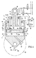
- FIGS. 1 to 4 on the one hand, and on the other hand in FIGS. 5 to 10, the same parts are designated with the same reference numerals.
- the suspension system according to the invention consists of at least one hydraulic piston-cylinder unit 2 and a spring accumulator 4 that cooperates with it, in particular pneumatic spring accumulator 4, the spring accumulator 4 and the piston-cylinder unit 2 in these embodiments according to FIGS. 1 and 2 are arranged independently, spatially separated and connected to one another via a hydraulic line connection 6.
- the piston-cylinder unit 2 consists of a cylinder 8 in which a piston 10 is guided so as to be axially movable.
- the piston 10 is mechanically connected to a piston rod 12, which is guided to the outside in a sealed manner against the cylinder 8 via a circumferential seal 14.
- the piston rod 12 has a connector 16, and the cylinder 8 also has a connector 18 at its opposite, closed end.
- the connecting piece 16 of the piston rod 12 can be fastened to a "sprung mass", for example a vehicle frame, while the connecting piece 18 of the cylinder 8 can be connected to a "unsprung mass", in particular a vehicle wheel 20 indicated only by dash-dotted lines.
- the spring accumulator 4 has a cylinder housing 22 in which a separating piston 24 is guided in a floating, ie freely movable, manner is. Within the cylinder housing 22, this separating piston 24 separates a spring chamber 26 filled with a compressible medium, in particular compressed air, from a compensating chamber 28.
- the spring accumulator 4 also has a filling connection 30 opening into the spring chamber 26.
- the separating piston 24 is connected to the sealing element via a peripheral seal 32 Sealed inner wall of the cylinder housing 22.
- the piston-cylinder unit 2 and the compensation chamber 28 are now filled with a hydraulic medium, so that when the piston 10 moves, a corresponding volume of the hydraulic medium flows back and forth between the cylinder 8 and the compensation chamber 28 of the spring accumulator 4. This also results in a displacement of the separating piston 24 against the pneumatic spring action of the medium contained in the spring chamber 26 in a manner known per se.
- the compressible medium acts on the separating piston 24 from the side of the spring chamber 26 with a pneumatic pressure p pn , while the hydraulic medium acts in the compensation chamber 28 with a pressure p hy against the separating piston 24.
- the pneumatic pressure p pn is now lower , and preferably significantly lower than the hydraulic pressure p hy .
- the separating piston 24 is designed according to the invention as a pressure transducer with two differently sized pressure surfaces 34 and 36.
- the first pressure surface 34 facing the spring chamber 26, which is acted upon by the pneumatic pressure p pn is larger than the opposite second pressure surface 36 acted on by the hydraulic pressure p hy .
- the separating piston 24 is, according to the invention, with a separating piston rod 38 connected by the Compensation chamber 28 and extends outwards from the cylinder housing 22 in a sealed manner via a circumferential seal 40.
- the compensation chamber 28 is thus arranged in a ring between the cylinder housing 22 and the separating piston rod 38.
- the pressure ratio p pn : p hy can also be changed according to the invention by varying the ratio between the inner cross section of the cylinder housing 22 and the cross section of the separating piston rod 38.
- the movement of the piston 10 in the cylinder 8 is now also transmitted to the separating piston 24 via the hydraulic medium, in particular with a step-down ratio (negative transmission).
- the spring accumulator 4 is arranged separately from the piston-cylinder unit 2.
- a connection 42 of the cylinder housing 22 opening into the compensation chamber 28 is connected to a connection 44 of the piston-cylinder unit 2 via the external line connection 6.
- a damping valve 46 which is adjustable in particular depending on the load, is preferably arranged in the external line connection 6.
- This damping valve 46 has an adjusting element 48, which can be acted upon by the switching pressure 50 with the hydraulic pressure P hy present .
- a shut-off valve 52 is advantageously arranged in the line connection 6, with which the spring action can be “switched off” according to the invention, ie the piston-cylinder unit 2 can be blocked.
- a leveling valve arrangement 54 is also advantageously connected to the connection 44 of the piston-cylinder unit 2, which - as can be clearly seen from the drawing - is designed in such a way that the piston-cylinder unit 2 can optionally be connected to a pressure line P or a return line T, for example a vehicle hydraulic system.
- the piston 10 is designed as a plunger (plunger) guided in a cylinder space 56.
- the cylinder chamber 56 is connected via a channel 58 which runs axially through the piston 10 and through the piston rod 12 to the connection 44 arranged in the outwardly directed end region of the piston rod 12.
- the piston 10 is against the at least one circumferential seal 60 according to the invention
- Cylinder 8 seals and thereby divides the cylinder space 56 opposite the piston rod 12 from an annular space 62 surrounding the piston rod 12.
- the cylinder chamber 56 is in turn connected via the axial channel 58 of the piston rod 12 to the connection 44 already mentioned.
- the annular space 62 is also connected according to the invention via an axial channel 64 to a connection 66 which is preferably also arranged in the outward end region of the piston rod 12.
- connection 66 of the annular space 62 is connected according to the invention on the one hand via the shut-off valve 52 to the connection 44 of the cylinder space 56 and on the other hand also via the damping valve 46 to the connection 42 of the cylinder housing 22 or the compensation space 28 of the spring accumulator 4 via an external line connection 68.
- the piston-cylinder unit 2 and the spring accumulator 4 are advantageously combined into one unit.
- the same or equivalent parts are nevertheless designated by the same reference numerals as in FIGS. 1 and 2.
- the cylinder housing 22 of the spring accumulator 4 forms part of the piston-cylinder unit 2, the separating piston rod 38 being hollow here and forming the cylinder 8 of the piston-cylinder unit 2.
- the cylinder chamber 56 is then either connected internally to the compensation chamber 28, which surrounds the separating piston rod 38 or the cylinder 8 in an annular manner, for which purpose the cylinder 8 has at least one radial flow opening 70 in the region of its wall adjacent to the separating piston 24.
- a damping valve 72 can preferably be arranged in the or each flow opening 70.
- the cylinder 8 and the cylinder housing 22 can each have an on have 74 for an external line connection 76, which is shown in dashed lines in Fig. 4.
- the above-mentioned, in particular load-dependent adjustable damping valve 46 can then advantageously be arranged in this external line connection 76.
- the line connection 76 is designed to be flexible.
- connection 44 which is connected to the cylinder chamber 56 via the axial channel 58 of the piston rod 12, is used exclusively for connecting the leveling valve arrangement 54.
- the piston-cylinder unit 2 is equipped according to the invention with a hydraulic end position shock absorber acting in the direction of deflection.
- an axial control pin 78 is preferably arranged within the cylinder 8, which extends from a cylinder bottom surface 80 in the direction of the axial channel 58 of the piston 10 and the piston rod 12 connecting the cylinder space 56 with the connection 44.
- This control pin 78 has, according to the invention, a cross section which is reduced in the direction of its free end 82 such that a throttle channel 84 with a flow cross section which changes as a function of the piston movement is formed between the control pin 78 which dips into the channel 58 and the axial channel 58. It is essential that this throttle channel 84 still has a certain minimum flow cross-section in the deflection end position of the piston 10. The meaning and purpose of this training will be explained in more detail below.
- the piston-cylinder unit 2 advantageously also has hydraulic end-position shock absorption that acts in the rebound direction in addition to the compression shock absorption.
- the cylinder-annular space 62 in its end region axially facing away from the piston 10 has an annular gap region 88 which is reduced in cross-section in particular by a radially inwardly projecting annular step 86 of the cylinder 8.
- the channel 64 connecting the annular space 62 with its connection 66 has in the direction of the Annular space 62 has an orifice 90 which can be seen in FIG.
- the channel 64 and the annular space 62 i.e.
- a throttle channel (not designated) with a flow cross-section that changes as a function of the piston movement is formed. It is also essential here that the throttle channel still has a certain minimum flow cross section in the rebound end position of the piston 10. This is also explained in more detail below.
- the spring accumulator 4 for the separating piston 24 is also equipped with hydraulic end position shock absorption, which acts here in particular in the rebound direction, ie in the relaxation direction of the pneumatic spring.
- this end position shock absorption roughly corresponds to the design for the piston-cylinder unit 2 in the rebound direction.
- the separating piston 24 has on the side of the compensation space 28 an axial, concentric annular web 92 such that between this annular web 92 and the inner wall of the cylinder dergephaseuses 22 a small annular gap 94 is formed.
- connection 42 opening into the compensation chamber 28 is arranged in the end region of the compensation chamber 28 which faces axially away from the separating piston 24 and in this case has an opening which has a surface shape which tapers axially in the direction of the separating piston 24, in particular in the form of a pear, analogously to the opening 90 according to FIG owns.
- a throttle channel with a flow cross section which changes as a function of the separating piston movement is formed between the connection 42 and the compensation chamber 28.
- this throttle channel in the rebound end position of the separating piston 24 still has a certain minimum flow cross-section, for which purpose in particular the annular web 92 of the separating piston 24 has radial throughflow openings 96, for example in the form of recesses or holes.
- the piston-cylinder unit 2 can have a sensory measuring device 98 for detecting its level position.
- a sensory measuring device 98 for detecting its level position.
- two protective sensors 102a and 102b offset in relation to one another in the axial direction can be arranged on a protective sleeve 100 which surrounds the piston-cylinder unit 2 and which is preferably fastened to the free end of the piston rod 12 and extends with a diameter-enlarged section concentrically freely over the cylinder 8.
- These measurement sensors 102a, 102b react to the cylinder wall of the cylinder 8 and, depending on the position relative to the cylinder 8, generate measurement signals which are evaluated in a control circuit (not shown) for level adjustment via the leveling valve arrangement 54.
- the measuring sensors 102a, b can be stationary or axial be slidably supported on the protective cover 100.
- the annular compensation chamber 28 has a cross-sectional area of 90 cm2 and the separating piston 24 has an effective pressure surface 34 of 900 cm2 facing the spring chamber 26, then according to the invention a pneumatic pressure p pn of 25 bar to carry a load of 7500 kp with the piston-cylinder unit 2.
- Pneumatic pressure p pn x pressure surface 34 of the separating piston 20 hydraulic pressure p hy x annular pressure surface 36 of the separating piston 24.
- shut-off valve 52 is switched into its blocking position.
- the hydraulic connection between the cylinder chamber 56 and the spring accumulator 4 is interrupted, so that the piston-cylinder unit 2 is "supported" on the incompressible hydraulic medium.
- the piston-cylinder unit 2 can be retracted and extended according to the invention.
- hydraulic medium is fed from the pressure line P into the piston-cylinder unit 2, i.e. through the leveling valve arrangement 54. inserted into the cylinder space 56. This results in an increase in the volume of the cylinder space 56, so that the piston-cylinder unit 2 "extends".
- the leveling valve arrangement 54 is switched to a switch position in which the cylinder space 56 is connected to the return line T, so that hydraulic medium can flow out of the piston-cylinder unit 2.
- the shut-off valve 52 is switched to its flow position according to the invention. If the two measuring sensors 102a, 102b show no signal, since they are both "above” the cylinder surface, the leveling valve arrangement 54 is switched to its lowering position described above, in which hydraulic medium can flow to the return line T, which then causes the piston-cylinder unit 2nd drives in. The leveling valve arrangement 54 remains in this position until the measuring device 98 indicates the correct level position. When leveling, no hydraulic medium flows out of the compensation chamber 28, since the damping valve 46 according to the invention has a high flow resistance in this flow direction.
- the leveling valve arrangement 54 is switched to a position in which hydraulic medium is supplied to the piston-cylinder unit 2 from the pressure line P.
- the leveling is ended according to the invention when the sensor 102a is above and the sensor 102b is below the cylinder surface.
- the load-dependent damping setting of the damping valve 46 is carried out by briefly actuating the switching valve 50, as a result of which the hydraulic pressure p hy acts on the adjusting element 48 of the damping valve 46.
- the adjustment is designed according to the invention such that a high damping effect (throttling) is effective at high pressure p hy and less throttling is effective at low pressure p hy .
- the essential advantage of the hydropneumatic suspension system according to the invention is that a very flat spring characteristic can be realized, which results in a very high level of suspension comfort.
- very flat spring characteristic large spring travel is retained when the vehicle is empty and fully loaded due to the leveling according to the invention.
- the disadvantage of the very flat spring characteristic that the piston-cylinder unit 2 can be pushed very easily into its end stop when quickly crossing an obstacle, is eliminated according to the invention by the hydraulic end stop shock absorption.
- the mode of action This hydraulic, displacement and speed dependent shock absorption is as follows. When deflected, the control pin 78 is displaced axially into the channel 58. As a result, the flow cross section of the throttle duct 84 changes continuously except for a narrow annular gap.
- the end position shock absorption according to the invention advantageously also ensures that the piston-cylinder unit 2 is pushed apart very gently from its completely collapsed position, instead of ripping apart at a high initial speed from its completely collapsed position due to the increased pressure p pn in the spring chamber 26. If the cylinder has then moved apart a certain distance, the pneumatic pressure p pn has advantageously already dropped so far that the forces which push the piston-cylinder unit apart are correspondingly lower.
- the end position shock absorption accordingly not only suppresses the shock when the piston-cylinder unit 2 is pushed together, but advantageously also has the consequence that the piston-cylinder unit 2 moves apart gently and not jerkily. Too fast apart would have the consequence that Shock forces occur on a vehicle frame, caused by the impact of a wheel on the road.
- the mode of operation is essentially the same as in the embodiment according to FIG. 1.
- the hydraulic medium displaced from the cylinder space 56 during the piston movement only flows partially into the compensation space 28, because a partial volume also flows via the line connection 68 and the channel 64 into the annular space 62, the volume of which increases as the spring deflects.
- the volume displaced into the compensation space 28 corresponds to the volume of the piston rod 12 that is displaced into the cylinder 8. This in turn increases the pneumatic pressure p pn .
- rebounding (arrow direction 105) there is a hydraulic flow in the opposite direction, ie on the one hand from the compensation chamber 28 and on the other hand from the annular space 62 back into the cylinder space 56.
- the blocking and leveling takes place analogously to the embodiment according to FIG. 1.
- a wheel can now additionally be raised and lowered when used in a motor vehicle. This is possible by dividing the interior of the cylinder 8 into the cylinder space 56 and the annular space 62, ie through the peripheral seal 60.
- the shut-off valve 52 is first switched to its blocking position.
- the leveling valve arrangement 54 is switched into a switching position in which the cylinder space 56 is connected to the return line T via the connection 44.
- hydraulic medium can flow out of the cylinder space 56.
- the Pneumatic pressure p pn displaced hydraulic medium from the compensation piston 28 from the compensation chamber 28 via the line connection 68, the connection 66 and the axial channel 64 into the annular chamber 62.
- the piston-cylinder unit 2 moves together, as a result of which the corresponding wheel 20 is raised in a vehicle. It is particularly advantageous here that the separating piston 24 is displaced a very small distance compared to the piston 10, so that the pneumatic pressure p pn in the spring chamber 26 also drops only slightly. This ensures that the piston-cylinder arrangement 2 can be retracted completely. Another advantage of this solution is that the retraction can be done without the vehicle hydraulics, ie without pumping power. If the piston-cylinder unit 2 is subsequently to be moved apart again, the cylinder chamber 56 is connected to the pressure line P via the leveling valve arrangement 54. As a result, hydraulic medium flows into the cylinder space 56.
- the mode of action of the end position shock absorption in the deflection direction is analogous to the embodiment according to FIG. 1.
- an end position shock absorption in the rebound direction is also provided.
- This shock absorption prevents the piston-cylinder unit 2 from moving apart very hard against the mechanical end stop, for example when a wheel drives over a deep pothole, thereby high mechanical stress on the cylinder would occur. Furthermore, a hard impact would also lead to unpleasant noises in the vehicle and to impacts on the vehicle frame.
- the hydraulic shock absorption in the rebound direction works as follows. If the piston-cylinder unit 2 moves completely apart, the larger opening part of the orifice opening 90 of the channel 64 (see FIG. 3) reaches the narrowed annular gap region 88 of the cylinder 8.
- end position shock absorption is therefore provided both in the compression and in the rebound direction.
- the deflection shock absorption (control pin 78 in connection with the axial channel 58) starts from a middle level position of the piston-cylinder unit, for example after about 20 mm travel in the direction of deflection.
- the rebound shock absorption (annular gap area 88 in connection with the mouth opening 90 of the channel 64) also sets, for example, approximately from the middle position 20 mm path seen in the rebound direction, however.
- ⁇ 20 mm of spring travel are undamped and only a travel-dependent damping of the suspension system is used for larger spring travel.
- This solution has the decisive advantage that the entire hydropneumatic suspension system experiences almost no heating, which results in very good suspension comfort.
- a wheel predominantly makes only slight lifting movements during normal road travel. If these small lifting movements were dampened, heat would be generated unnecessarily and impacts would also be transmitted to the vehicle frame. This is advantageously avoided by the invention.
- shock absorption of the spring accumulator 4 advantageously prevents the separating piston 24 from mechanically colliding against its stop by the pneumatic pressure p pn . This means that the separating piston 24 moves slowly and braked into its end stop due to a hydraulic throttling, the ring web 92 then resting on the end of the bottom end of the cylinder housing 22.
- the flow openings 96 are formed in the annular web 92 according to the invention, which ensures that hydraulic medium can apply pressure p hy to pressure surface 36 of separating piston 24 against pressure p pn .
- the mode of operation is as follows. If the piston 10 is pushed into the cylinder 8 via the piston rod 12, hydraulic medium is displaced from the cylinder space 56 via the flow openings 70 and / or the external line connection 76 into the compensation space 28 which surrounds the cylinder 8 in a ring. As a result, the separating piston 24 is displaced against the pressure p pn of the compressible medium in the spring chamber 26. The pressure p pn rises accordingly, and with it the pressure p hy in the cylinder chamber 56 and in the compensation chamber 28. If the piston 10 with the piston rod 12 is moved out of the cylinder 8 again, the hydraulic medium flows out of the compensation chamber 28 back into the cylinder chamber 56. The separating piston 24 also moves back so that the pressure p pn drops accordingly.
- Leveling is possible in the manner already described above via the leveling valve arrangement 54, by either supplying hydraulic medium from the pressure line P into the cylinder space 56 or removing it from the cylinder space 56 to the return line T via the connection 44 and the channel 58.
- Damping is possible either via the internal damping valves 72 or via the external damping valve 46. Furthermore, damping valves can possibly be omitted entirely if the cross section of the radial flow openings 70, for example, is selected to be correspondingly small.
- the separating piston 24 according to the invention has a recess 106 on its side facing the pneumatic spring chamber 26, which advantageously ensures that a minimum residual volume is also present in the end stop of the separating piston 24 the compressible medium remains, so that an impermissibly high pressure rise is advantageously avoided.
- the suspension system according to the invention in further embodiments likewise consists of at least one hydraulic piston-cylinder unit 202, but according to the invention there are two, in particular hydropneumatic spring accumulators 204, 206 which cooperate with them and which are in the preferred embodiments independent of the invention, ie arranged spatially separate from the piston-cylinder unit 202 and connected via a hydraulic line connection 208, 210.
- the piston-cylinder unit 202 consists of a cylinder 212 in which a piston 214 is guided so as to be axially movable.
- the piston 214 is mechanically connected to a piston rod 216 which acts against the cylinder 212 via a circumferential seal 218 is guided sealed to the outside.
- the piston rod 216 has a connector 220
- the cylinder 212 also has a connector 222 at its opposite, closed end.
- the connecting piece 220 of the piston rod 216 can preferably be fastened to a "sprung mass", for example a vehicle frame, while the connecting piece 222 of the cylinder 212 can be connected to a "unsprung mass", in particular a vehicle wheel 224 which is only indicated by dash-dotted lines.
- the piston 214 is sealed against the inner wall of the cylinder 212 via at least one circumferential seal 226 and thereby divides two pressure chambers which can be changed in opposite directions from one another, namely a cylinder chamber 228 opposite the piston rod 216 from an annular chamber 230 surrounding the piston rod 216 guided end region of the piston rod 216 on the one hand a first connection 232, which opens into the cylinder chamber 228 via an axial channel 234 of the piston rod 216, and on the other hand a second connection 236, which likewise opens into the annular chamber 230 via an axial channel 238 of the piston rod 216.
- the spring accumulators 206, 204 are connected to the connections 232 and 236 via the line connections 210, 208.
- the piston 214 has two opposing, effectively pressurized piston surfaces, namely a piston end face 240 facing the cylinder chamber 228 and a piston ring surface 242 smaller in area than the end face 240 and facing the annulus.
- each of the two spring accumulators 204, 206 is designed as a piston accumulator with a separating piston 246 guided in a floating manner in a cylinder housing 244.
- the separating piston 246 separates within the cylinder housing 244 a storage space 248 hydraulically connected to the respective pressure chamber 228, 230 of the piston-cylinder unit 202 from a spring chamber 250 filled with the compressible medium.
- a gas is preferably used as the compressible medium, but can be used in particular for high "pneumatic” Also press e.g. Silicone or the like medium can be used. The term “pneumatic" thus does not limit the invention to gases.
- the compressible media in the spring chambers 250 of the two spring accumulators 204, 206 are each acted upon with a pneumatic preload pressure p1 and p2 such that preferably different hydraulic pressures p3 and p3 prevail in the two pressure chambers 228 and 230 of the piston-cylinder unit 202.
- a pneumatic preload pressure p1 and p2 such that preferably different hydraulic pressures p3 and p3 prevail in the two pressure chambers 228 and 230 of the piston-cylinder unit 202.
- F1 end face 240 times pressure p4 (Fig. 5) or p. (Fig. 6)
- F2 ring area 242 times pressure p3 (Fig. 5) or p4 (Fig. 6).
- the annular space 230 with its connected spring accumulator 204 forms a closed, purely volume-controlled hydraulic circuit A, while the cylinder space 228 with its connected spring accumulator 206 forms a load-controlled hydraulic Circuit B forms.
- This load-controlled circuit B can preferably be connected to a pressure line P or a tank line T of a hydraulic system via a leveling valve arrangement 252.
- the volume-controlled spring accumulator 204 can be made smaller than the load-controlled spring accumulator 206. 5 is particularly suitable for applications in which the load on the piston-cylinder unit is variable, ie not constant.
- the spring accumulators work with low pressures and relatively small volumes of compressible media.
- the embodiment according to FIG. 6 is particularly suitable for applications in which the load is constant.
- the volume-controlled spring accumulator 204 is then connected to the cylinder chamber 228, while the load-controlled spring accumulator 206 is connected to the annular chamber 230 and also to the leveling valve arrangement 252.
- particularly small storage volumes can be provided, but in this case the pressures become correspondingly higher than in the system according to FIG. 5.
- a blocking valve 254 is arranged in the line connection 10 between the spring accumulator 206 of the load-controlled hydraulic circuit B and the pressure chamber connected to the leveling valve arrangement 52 (in FIG. 5 cylinder chamber 228 and in FIG. 6 annular chamber 230).
- a damping valve 256 which is adjustable in particular depending on the load, is also arranged in this line connection 210 (only shown in FIG. 7).
- the separating piston 26 at least one of the two spring accumulators, but preferably - as shown - each of the two spring accumulators 204, 206, as a pressure transducer with two differently sized, effective pressure surfaces 258, 260. It is particularly advantageous if the spring chamber 250 facing, acted upon by the preload pressure p1 or p2, the first pressure surface 258 is larger than the opposite, pressurized by the hydraulic pressure p3 or p4, the second pressure surface 260. As a result, according to the invention, the preload pressure p1 or p2 is in each case less than the hydraulic pressure p3 or p4.
- the term "effective pressure surface” is understood to mean the surface of the separating piston which is acted upon by the pneumatic or hydraulic pressure and which is decisive for the creation of a displacement force acting in the direction of movement of the separating piston 246.
- the separating piston 246 can advantageously be equipped with a simplified “oil seal” instead of the “gas seal” that was previously required, consisting of at least three to five individual seals, since the pressure of the compressible medium, in particular compressed air, is opposed by the higher pressure of the hydraulic medium . This contributes to the desired compact design, since the separating piston 246 can be designed with only one peripheral seal and therefore with a much shorter axial length.
- This circumferential seal advantageously only has to be designed for the differential pressure between the pneumatic and the hydraulic pressure.
- a further advantage here is that, due to the higher hydraulic pressure of the piston-cylinder unit, the pressure surface, ie the end surface 240 of the piston 214 which receives the load, is smaller and thus the piston-cylinder unit 202 itself is also com pact can be trained.
- a further advantage is that the frictional force of the separating piston 246 is significantly reduced by the configuration according to the invention. Since the pneumatic pressure is lower than the hydraulic pressure, the circumferential seal of the respective separating piston 246 is also only subjected to the differential pressure and therefore has a correspondingly low friction. This is particularly advantageous for dynamic processes and contributes to optimal suspension properties.
- separating pistons 246 are connected according to the invention - analogously to FIGS. 1 to 4 - in each case with a separating piston rod 262, which extends through the storage space 248 and through a circumferential seal 264 in a sealed manner from the cylinder housing 244 to the outside.
- the storage space 248 thus has an annular cross section which is reduced in relation to the inner cross section of the spring chamber 250 or the cylinder housing 244 and is concentric with the separating piston rod 262.
- the pressure ratio p 1: p 3 or p 2: p8 can also be determined here according to the invention.
- the suspension movements of the piston-cylinder unit 202 ie the movements of the piston 214 in the cylinder 212, are also transmitted to the respective separating piston 246 via the hydraulic medium, in particular with a reduction (negative translation).
- this embodiment corresponds to that of FIGS. 1 and 2, so that reference can be made to this.
- the leveling valve arrangement 252 is advantageously possible for the leveling valve arrangement 252 to adjust the level position of the piston-cylinder unit 202 from a respective actual level to a predetermined target level as a function of the the position of the separating piston 246 of the volume-controlled spring accumulator 204 proportional to the respective actual level.
- the separating piston rod 262 is connected to a displacement sensor 266, the leveling valve arrangement being controlled by means of the output signals of this displacement sensor 266 via a control unit 268 (shown in broken lines in FIG. 5).
- This configuration is particularly advantageous insofar as the travel reduction of the separating pistons 246 described above has a stroke which is very much smaller than that of the spring movements of the piston-cylinder unit 2, so that consequently also a small, compact and therefore very inexpensive displacement sensor 66 can be used.
- the costs for the displacement sensor 266 according to the present invention are reduced to approximately 1/10.
- monitoring for leaks in the hydraulic medium and / or the compressible medium takes place at least temporarily, but preferably continuously.
- a control unit for example the control unit 268 (FIG. 5) already mentioned
- a maximum possible range of motion of the separating piston 246 of the volume-controlled spring accumulator 204 determined by the end positions of the piston-cylinder unit 202 is determined by two target limit values and the respective actual value Position of the separating piston 246 is monitored via the displacement sensor 266, an error message being generated if the actual position lies outside the range of movement of the separating piston 246 determined by the target limit values.
- Such a position of the separating piston 246 outside of this limit range is only possible if a leakage occurs at any point in the system and medium escapes.
- the suspension system according to the invention now also opens up the possibility of changing the load-bearing force F piston forces F 1 and F 2 in static and / or dynamic operation by merely changing the pneumatic preload pressures p 1, p 2.
- the spring chamber 250 is connected to at least one of the two spring accumulators 204, 206, in the exemplary embodiment shown in FIG. 5, by way of example only of the volume-controlled spring accumulator 204, via a connection 270 and a pressure line 272 to a pressure setting device 274, which is, for example a pneumatic pressure source and a corresponding switching valve can act.
- a simple adaptation of the system to different operating states is possible (setting of load conditions, degree of impact, etc.).
- suspension system according to the invention is equipped with a load detection device 276, which determines the load acting on the piston-cylinder unit 202 qualitatively and / or quantitatively.
- the load detection device 276 has a displacement sensor 278 connected to the separating piston rod 262 of the load-controlled spring accumulator 206. Via this displacement sensor 278, ie on the basis of the position of the separating piston 246 of the load-controlled spring accumulator 206, the load detection device 276 generates load-proportional signals S. These signals S can advantageously be evaluated for visual and / or acoustic display.
- signals S are fed directly to a tachograph, which then registers the respective state of charge in an easily verifiable manner.
- a qualitative signal (optical / acoustic) can also be triggered only when a certain load limit value is exceeded.
- the load can also be shown quantitatively, for example on a digital display.
- the signal S can also advantageously be evaluated to trigger certain subsequent reactions, such as, for example, an interruption in the ignition and / or the brakes being blocked when a maximum load is exceeded.
- the position of the separating piston 246 of the load-controlled spring accumulator 206 is always absolutely proportional to the load, even if the level of the piston-cylinder unit 202 should be raised via the leveling valve arrangement 252. Because when hydraulic medium is supplied from the pressure line P via the leveling valve arrangement 252, this flows - assuming a constant load - exclusively into the piston-cylinder unit 202, since the pneumatic pressure p 2 in the load-controlled spring accumulator 206 does not change at a constant load. Out For this reason, a particularly simple way of checking or determining the load would be to merely determine the length of the section of the separating piston rod 262 which projects outwards, the respective lengths belonging to the load values having to be determined beforehand. The load could then be determined by a simple scale in the area of the outwardly extending separating piston rod 262.
- the load detection device 276 By means of the load detection device 276 according to the invention, it is advantageously possible to determine the load even when the level of the vehicle has been raised by means of the leveling valve arrangement 252, as a result of which, at first glance, a low load should actually be inferred.
- the only decisive factor is the level of the pneumatic pressure p2, which can be detected indirectly via the position of the separating piston 246 in the manner described.
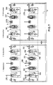
- FIGS. 7 to 9 now show application examples of the suspension system according to the invention for a multi-axle, here four-axle vehicle.
- two piston-cylinder units 202 are hydraulically connected in pairs.
- the two annular spaces 230 are connected to the same, volume-controlled spring accumulator 204, while the cylinder spaces 228 are each connected to their own load-controlled spring accumulator 206.
- the interconnected piston-cylinder units 202 are each arranged on the same side of the vehicle - with respect to the central vehicle axis arranged in the direction of travel - and each with a wheel of a dual vehicle axis connected.
- the configuration according to the invention has an advantageous effect in that automatic roll or tilt stabilization of the vehicle is achieved.
- a vehicle leans outward in the opposite direction to the curve.
- the vehicle leans to the right in a left curve and to the left in a right curve.
- This phenomenon is practically automatically counteracted by the invention, since the load capacity F increases progressively when the piston-cylinder units 202 are deflected. This is because the force F1 is greater and the force F2 is smaller.
- an analogous effect is advantageously also achieved when braking and accelerating.
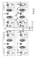
- FIG. 7 shows an embodiment with damping valves 256 which can be adjusted as a function of the load, but which, due to the invention, can also be omitted if the system sizes are selected appropriately, as can be seen in FIGS. 8 and 9.
- each wheel that is to say each piston-cylinder unit 202
- each wheel can be separately lowered and raised, for which purpose the respective blocking valve 254 is switched into the blocking position and hydraulic medium is supplied or discharged via the leveling valve arrangement 252 9
- each interconnected pair of piston-cylinder units 202 is equipped with only one common leveling valve arrangement 252, so that here, on the one hand, the leveling and, on the other hand, the lifting and lowering, each together follows. This simplifies the hydraulic circuit for those applications in which the lifting and lowering of individual wheels or piston-cylinder arrangements 202 is not required.
- the line connection 208 is also between an adjustable damping valve 290 is arranged in the piston-cylinder unit 202 and the volume-controlled spring accumulator 204.
- the computer 292 evaluates the measurement results of all the distance measuring devices 266, 278 and / or the accelerometer.
- the computer 292 also takes into account the state of loading of the vehicle.
- the loading state is determined by the displacement sensors 278 or by pressure sensors on the spring accumulators 206 of the piston chambers 228.
- the damping valves 256, 290 are adjusted in accordance with the measurement result.
- the damping valves 256, 290 are designed so that - depending on the setting - they only open at a more or less large pressure difference.
- pressure differences ⁇ p DK and ⁇ p DR for the individual piston-cylinder units 202 can be set differently depending on the individual measurement results (loading, displacement measurement, acceleration measurement, speed, brake pressure etc.).
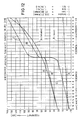
- FIGS. 11 and 12 show an example of the influence of the adjustable damping valves 256, 290.
- the characteristics of the front axle are shown in FIG. 11 and those of the rear axle are shown in FIG. 12.
- Curve A is the normal spring curve (loaded / unloaded).
- Curve B is a damper throttling at 10 bar.
- Curve C is a damper throttling at 50 bar.
- the present invention achieves significant advantages over the prior art.
- the load-bearing capacity according to the invention is now determined almost by the entire piston end face 240, since the opposing force F2 can be kept very small, namely by the small piston ring surface 242 in conjunction with a small pressure.
- the entire piston-cylinder unit 202 can be made very compact with a small cross-section, with the additional advantage that the total volume of the hydraulic medium in the system can be reduced.
- the invention is not limited to the exemplary embodiments shown and described, but also encompasses all embodiments having the same effect in the sense of the invention.
- the illustrated and described solutions for end position shock absorption are only examples. Any other construction can also be used in which the hydraulic flow is throttled depending on the path of the piston or the separating piston.
- the invention is also not limited to the use of the piston-cylinder units described and illustrated. Rather, such pistons can, for example cylinder units are used which have two annular cylinder spaces (so-called “inner tube cylinder", as described for example in DE-OS 38 39 446). At least one of the spring accumulators can also be arranged integrated within the piston-cylinder unit. Other types of spring accumulators can also be used.
Landscapes
- Engineering & Computer Science (AREA)
- General Engineering & Computer Science (AREA)
- Mechanical Engineering (AREA)
- Physics & Mathematics (AREA)
- Acoustics & Sound (AREA)
- Aviation & Aerospace Engineering (AREA)
- Vehicle Body Suspensions (AREA)
- Fluid-Damping Devices (AREA)
Applications Claiming Priority (6)
| Application Number | Priority Date | Filing Date | Title |
|---|---|---|---|
| DE19893936034 DE3936034A1 (de) | 1989-10-28 | 1989-10-28 | Hydropneumatisches federungssystem |
| DE3936034 | 1989-10-28 | ||
| DE4008831 | 1990-03-20 | ||
| DE19904008831 DE4008831C2 (de) | 1990-03-20 | 1990-03-20 | Hydropneumatisches Federungssystem |
| DE4031044 | 1990-10-01 | ||
| DE4031044 | 1990-10-01 |
Publications (3)
| Publication Number | Publication Date |
|---|---|
| EP0425885A2 true EP0425885A2 (fr) | 1991-05-08 |
| EP0425885A3 EP0425885A3 (en) | 1991-09-11 |
| EP0425885B1 EP0425885B1 (fr) | 1994-07-20 |
Family
ID=27200368
Family Applications (1)
| Application Number | Title | Priority Date | Filing Date |
|---|---|---|---|
| EP90119816A Expired - Lifetime EP0425885B1 (fr) | 1989-10-28 | 1990-10-16 | Système à ressort hydropneumatique |
Country Status (5)
| Country | Link |
|---|---|
| US (1) | US5246247A (fr) |
| EP (1) | EP0425885B1 (fr) |
| BR (1) | BR9005451A (fr) |
| DE (1) | DE59006499D1 (fr) |
| ES (1) | ES2060888T3 (fr) |
Cited By (15)
| Publication number | Priority date | Publication date | Assignee | Title |
|---|---|---|---|---|
| EP0529320A1 (fr) * | 1991-08-22 | 1993-03-03 | HEMSCHEIDT FAHRWERKTECHNIK GmbH & Co. | Système de ressort oléopneumatique pour l'essieu relevable d'un véhicule |
| EP0607545A1 (fr) * | 1992-12-02 | 1994-07-27 | Öhlins Racing Ab | Amortisseur |
| WO1994021209A1 (fr) * | 1993-03-18 | 1994-09-29 | Keymed (Medical & Industrial Equipment) Ltd. | Appareil reglable pour supporter une charge |
| EP0677679A3 (fr) * | 1994-04-15 | 1996-02-14 | Digitek Srl | Amortisseur hydraulique avec réaction à autoréglage. |
| DE29718807U1 (de) * | 1997-10-22 | 1998-02-05 | Liebherr-Werk Ehingen Gmbh, 89584 Ehingen | Achsfederung von Lastfahrzeugen und Arbeitsmaschinen |
| EP1745951A1 (fr) * | 2005-07-18 | 2007-01-24 | Hemscheidt Fahrwerktechnik GmbH & Co. KG | Dispositif de ressort pour véhicule |
| US7472914B2 (en) | 2005-02-28 | 2009-01-06 | Anderson Brian K | Suspension system |
| EP2058155A1 (fr) * | 2007-11-09 | 2009-05-13 | BAE Systems Hägglunds Aktiebolag | Dispositif de suspension et procédé pendant l'action de ressort et/ou l'action d'amortissement d'un véhicule |
| ITPR20090081A1 (it) * | 2009-10-20 | 2011-04-21 | Macro S R L | Sospensione idropneumatica e veicolo equipaggiato con tale sospensione |
| EP2052889B1 (fr) | 2007-10-26 | 2016-06-15 | Strömsholmen AB | Dispositif hydropneumatique à ressort-amortisseur et procédé de fonctionnement d'un dispositif hydropneumatique à ressort-amortisseur |
| DE102005001338B4 (de) * | 2003-11-05 | 2017-09-07 | Volkswagen Ag | Fahrzeug, insbesondere Kraftfahrzeug |
| EP3181943A4 (fr) * | 2014-08-11 | 2018-04-18 | KYB Corporation | Dispositif de suspension |
| RU187199U1 (ru) * | 2018-10-15 | 2019-02-22 | Российская Федерация, От Имени Которой Выступает Министерство Промышленности И Торговли Российской Федерации | Гидропневматическая рессора подвески транспортного средства |
| DE102014111799B4 (de) * | 2013-08-22 | 2020-02-27 | GM Global Technology Operations LLC (n. d. Ges. d. Staates Delaware) | Fahrzeugaufhängungssystem und Fahrzeug mit einem solchen |
| RU2854939C1 (ru) * | 2025-07-04 | 2026-01-22 | Федеральное государственное бюджетное образовательное учреждение высшего образования "Волгоградский государственный технический университет" (ВолгГТУ) | Амортизационный узел для пневмогидравлической рессоры подвески транспортного средства |
Families Citing this family (50)
| Publication number | Priority date | Publication date | Assignee | Title |
|---|---|---|---|---|
| WO1994008808A1 (fr) * | 1992-10-10 | 1994-04-28 | Hemscheidt Fahrwerktechnik Gmbh & Co. Kg | Systeme de suspension hydropneumatique |
| DE9407167U1 (de) * | 1994-04-29 | 1994-07-07 | Hemscheidt Fahrwerktechnik GmbH & Co. KG, 42109 Wuppertal | Hydropneumatisches Federungssystem mit Stabilisierung |
| US5765115A (en) * | 1995-08-04 | 1998-06-09 | Ford Motor Company | Pneumatic tilt stabilization suspension system |
| DE19844493A1 (de) * | 1998-09-29 | 2000-03-30 | Zahnradfabrik Friedrichshafen | Hydropneumatisches Federungssystem |
| DE10126458C2 (de) * | 2001-05-31 | 2003-06-12 | Daimler Chrysler Ag | Dichtheits- und Funktionsprüfung eines Sperrventils in einer pneumatischen Federung |
| DE10252729A1 (de) * | 2002-11-13 | 2004-06-03 | Hydac Technology Gmbh | Hydropneumatische Federung |
| DE102004038691A1 (de) * | 2003-09-27 | 2005-04-14 | Zf Friedrichshafen Ag | Wegmess-System für ein Kolben-Zylinderaggregat |
| US20100116608A1 (en) * | 2004-04-08 | 2010-05-13 | Hemscheidt Fahrwerktechnik Gmbh & Co. Kg | Suspension and damping device for motor vehicles |
| US8151953B2 (en) | 2004-04-08 | 2012-04-10 | Samsung Electronics Co., Ltd. | Suspension and damping device for motor vehicles |
| US20060021833A1 (en) * | 2004-04-08 | 2006-02-02 | Hemscheidt Fahrwerktechnik Gmbh & Co. Kg | Suspension and damping device for motor vehicles |
| DE202004005623U1 (de) | 2004-04-08 | 2005-08-11 | Hemscheidt Fahrwerktechnik Gmbh & Co. Kg | Federungs- und Dämpfungseinrichtung für Kraftfahrzeuge |
| DE102004027885A1 (de) * | 2004-05-28 | 2005-12-22 | Dr.Ing.H.C. F. Porsche Ag | Feder-Dämpfer-Einheit für ein Fahrwerk eines Kraftfahrzeuges |
| US9452654B2 (en) | 2009-01-07 | 2016-09-27 | Fox Factory, Inc. | Method and apparatus for an adjustable damper |
| US10060499B2 (en) | 2009-01-07 | 2018-08-28 | Fox Factory, Inc. | Method and apparatus for an adjustable damper |
| US20100170760A1 (en) | 2009-01-07 | 2010-07-08 | John Marking | Remotely Operated Bypass for a Suspension Damper |
| US9239090B2 (en) | 2009-01-07 | 2016-01-19 | Fox Factory, Inc. | Suspension damper with remotely-operable valve |
| US10047817B2 (en) * | 2009-01-07 | 2018-08-14 | Fox Factory, Inc. | Method and apparatus for an adjustable damper |
| US8627932B2 (en) | 2009-01-07 | 2014-01-14 | Fox Factory, Inc. | Bypass for a suspension damper |
| US11306798B2 (en) | 2008-05-09 | 2022-04-19 | Fox Factory, Inc. | Position sensitive suspension damping with an active valve |
| WO2009158329A2 (fr) | 2008-06-27 | 2009-12-30 | Absolute Electronic Solutions, Inc. | Véhicule tracteur de semi-remorque à plateau réglable |
| DE102008034582A1 (de) * | 2008-07-24 | 2010-01-28 | Liebherr-Hydraulikbagger Gmbh | Arbeitsgerät |
| EP2527171A1 (fr) | 2008-11-18 | 2012-11-28 | Hemscheidt Fahrwerktechnik GmbH & Co. KG | Système d'amortissement pour véhicules |
| US12491961B2 (en) | 2008-11-25 | 2025-12-09 | Fox Factory, Inc. | Seat post |
| US10036443B2 (en) | 2009-03-19 | 2018-07-31 | Fox Factory, Inc. | Methods and apparatus for suspension adjustment |
| US9140325B2 (en) | 2009-03-19 | 2015-09-22 | Fox Factory, Inc. | Methods and apparatus for selective spring pre-load adjustment |
| ATE555929T1 (de) * | 2008-12-12 | 2012-05-15 | Hemscheidt Fahrwerktech Gmbh | Dämpfungseinrichtung für fahrzeuge |
| US9038791B2 (en) | 2009-01-07 | 2015-05-26 | Fox Factory, Inc. | Compression isolator for a suspension damper |
| US11299233B2 (en) | 2009-01-07 | 2022-04-12 | Fox Factory, Inc. | Method and apparatus for an adjustable damper |
| US12122205B2 (en) | 2009-01-07 | 2024-10-22 | Fox Factory, Inc. | Active valve for an internal bypass |
| DE102009032897B4 (de) * | 2009-07-10 | 2013-09-19 | Stabilus Gmbh | Kolben-Zylinderaggregat |
| US8955653B2 (en) | 2009-10-13 | 2015-02-17 | Fox Factory, Incorporated | Methods and apparatus for controlling a fluid damper |
| US10697514B2 (en) | 2010-01-20 | 2020-06-30 | Fox Factory, Inc. | Remotely operated bypass for a suspension damper |
| US8591449B2 (en) | 2010-10-18 | 2013-11-26 | Dennis Sheanne Hudson | Vessel for storing fluid at a constant pressure across a range of internal deformations |
| DE102010051663A1 (de) * | 2010-11-17 | 2012-05-24 | Liebherr-Hydraulikbagger Gmbh | Arbeitsgerät |
| DE102010051664A1 (de) | 2010-11-17 | 2012-05-24 | Liebherr-Hydraulikbagger Gmbh | Arbeitsgerät |
| DE102011106260A1 (de) * | 2011-05-18 | 2012-11-22 | Liebherr-Hydraulikbagger Gmbh | Arbeitsgerät, insbesondere Bagger oder Maschine zum Materialumschlag |
| EP2530355B1 (fr) | 2011-05-31 | 2019-09-04 | Fox Factory, Inc. | Appareil pour amortissement de suspension sensible au positionnement et/ou réglable |
| TW201321623A (zh) * | 2011-07-26 | 2013-06-01 | Vale Sa | 氣動震動阻尼裝置 |
| EP2567839B1 (fr) | 2011-09-12 | 2019-03-13 | Fox Factory, Inc. | Procédés et appareil de réglage de suspension |
| DE102011121777B4 (de) | 2011-12-21 | 2018-11-08 | Ewo Fluid Power Gmbh | Doppeltwirkender Hydraulikzylinder mit integrierten Kolbenspeichern |
| US11279199B2 (en) | 2012-01-25 | 2022-03-22 | Fox Factory, Inc. | Suspension damper with by-pass valves |
| US10330171B2 (en) | 2012-05-10 | 2019-06-25 | Fox Factory, Inc. | Method and apparatus for an adjustable damper |
| CN103267081B (zh) * | 2013-05-10 | 2016-01-27 | 河南理工大学 | 一种用于工程机械或农用机械的压电发电式阻尼可调油气悬架 |
| US10737546B2 (en) | 2016-04-08 | 2020-08-11 | Fox Factory, Inc. | Electronic compression and rebound control |
| US10214071B1 (en) * | 2016-05-28 | 2019-02-26 | PAL Suspension LLC | Vehicle suspension system with multi-stage hydraulic cylinder assemblies and external spring packs |
| US20200102045A1 (en) * | 2017-03-22 | 2020-04-02 | Honda Motor Co., Ltd. | Steering damper |
| CN112211942B (zh) * | 2019-11-04 | 2021-12-17 | 北京京西重工有限公司 | 支架、液压阻尼器组件及其之间的连接方法 |
| US10737545B1 (en) | 2019-12-19 | 2020-08-11 | PAL Suspension LLC | Vehicle suspension system with multi-stage hydraulic cylinder assemblies and external spring packs |
| CN113217572B (zh) * | 2020-05-27 | 2022-09-27 | 北京京西重工有限公司 | 阻尼器组件 |
| JP7682932B2 (ja) * | 2020-06-09 | 2025-05-26 | アントニー, アシュリン | チェーンドライブのチェーン内の弛みおよび振動を除去するための装置 |
Family Cites Families (27)
| Publication number | Priority date | Publication date | Assignee | Title |
|---|---|---|---|---|
| GB337855A (en) * | 1929-08-16 | 1930-11-13 | Mactaggart Scott & Company Ltd | Improvements in air loaded and like accumulators |
| FR864361A (fr) * | 1940-03-26 | 1941-04-25 | Comp Generale Electricite | Câble armé avec dispositif de fixation |
| GB821697A (en) * | 1956-05-31 | 1959-10-14 | Loewy Eng Co Ltd | Hydraulic accumulator |
| US2937034A (en) * | 1956-10-12 | 1960-05-17 | Langen & Co | Gas-hydraulic spring suspension for vehicles |
| GB864361A (en) * | 1957-09-04 | 1961-04-06 | Gratzmuller Jean Louis | Improvements in or relating to hydraulic power systems |
| US2959410A (en) * | 1958-10-27 | 1960-11-08 | Jarry Hydraulics | Double stage oleo-pneumatic shock absorber |
| BE629947A (fr) * | 1962-04-25 | |||
| US3150867A (en) * | 1962-07-13 | 1964-09-29 | Gilbert H Droegkamp | Combination shock absorber and selflevelling device |
| US3363894A (en) * | 1965-07-09 | 1968-01-16 | Menasco Mfg Company | Dual spring rate shock strut |
| US3647239A (en) * | 1969-07-17 | 1972-03-07 | Tokico Ltd | Vehicle suspension mechanism |
| FR2076812A5 (fr) * | 1970-01-29 | 1971-10-15 | Gratzmuller J | |
| GB1306292A (fr) * | 1970-03-11 | 1973-02-07 | ||
| DE2020292A1 (de) * | 1970-04-25 | 1971-11-18 | Bosch Gmbh Robert | Abstuetzsystem fuer Kraftfahrzeuge |
| US3847410A (en) * | 1972-06-12 | 1974-11-12 | Monroe Belgium Nv | Leveling system |
| DE2403017A1 (de) * | 1974-01-23 | 1975-07-24 | Volkswagenwerk Ag | Mit zumindest einem druckmittel arbeitende federanordnung mit einer niveauregelung fuer fahrzeuge, insbesondere kraftfahrzeuge |
| JPS5169766A (fr) * | 1974-12-12 | 1976-06-16 | Yamaha Motor Co Ltd | |
| FR2411341A1 (fr) * | 1977-12-12 | 1979-07-06 | Messier Hispano Sa | Suspension oleopneumatique a orifices de laminage variables, notamment pour trains d'atterrissage d'aerodynes |
| FR2461852A1 (fr) * | 1979-07-17 | 1981-02-06 | Messier Hispano Sa | Perfectionnements aux amortisseurs et amortisseurs-verins notamment pour trains d'atterrissage d'aerodyne |
| DE3174727D1 (en) * | 1980-11-25 | 1986-07-03 | Bayerische Motoren Werke Ag | Suspension system for vehicles |
| JPS6026345U (ja) * | 1983-07-29 | 1985-02-22 | トキコ株式会社 | ハイドロ・ニュ−マチック サスペンション |
| DE3427902A1 (de) * | 1984-07-28 | 1986-02-13 | Franz Dr.-Ing. 7530 Pforzheim Tuczek | Steuerung von hydropneumatischen federelementen, insbesondere fuer kraftfahrzeuge |
| DE3618654C2 (de) * | 1986-06-03 | 1995-09-28 | Fichtel & Sachs Ag | Hydraulischer Schwingungsdämpfer für Fahrzeuge |
| DE3638574A1 (de) * | 1986-11-12 | 1988-05-26 | Rexroth Mannesmann Gmbh | Anordnung zur drucksteuerung eines daempfungszylinders fuer die abfederung von fahrzeugen |
| DE3702266A1 (de) * | 1987-01-27 | 1988-08-04 | Bayerische Motoren Werke Ag | Federelement fuer die radaufhaengung eines kraftfahrzeuges |
| JPS63301115A (ja) * | 1987-05-29 | 1988-12-08 | Nissan Motor Co Ltd | 油圧式サスペンション |
| US4798398A (en) * | 1987-08-12 | 1989-01-17 | Unit Rig & Equipment Co. | Dual rate equalizer suspension |
| DE3839446A1 (de) * | 1987-11-28 | 1989-06-15 | Hemscheidt Maschf Hermann | Hydro-pneumatischer stoss- und schwingungsdaempfer mit innenrohr |
-
1990
- 1990-10-16 EP EP90119816A patent/EP0425885B1/fr not_active Expired - Lifetime
- 1990-10-16 ES ES90119816T patent/ES2060888T3/es not_active Expired - Lifetime
- 1990-10-16 DE DE59006499T patent/DE59006499D1/de not_active Expired - Lifetime
- 1990-10-25 US US07/603,626 patent/US5246247A/en not_active Expired - Lifetime
- 1990-10-26 BR BR909005451A patent/BR9005451A/pt not_active IP Right Cessation
Cited By (17)
| Publication number | Priority date | Publication date | Assignee | Title |
|---|---|---|---|---|
| EP0529320A1 (fr) * | 1991-08-22 | 1993-03-03 | HEMSCHEIDT FAHRWERKTECHNIK GmbH & Co. | Système de ressort oléopneumatique pour l'essieu relevable d'un véhicule |
| EP0607545A1 (fr) * | 1992-12-02 | 1994-07-27 | Öhlins Racing Ab | Amortisseur |
| WO1994021209A1 (fr) * | 1993-03-18 | 1994-09-29 | Keymed (Medical & Industrial Equipment) Ltd. | Appareil reglable pour supporter une charge |
| EP0677679A3 (fr) * | 1994-04-15 | 1996-02-14 | Digitek Srl | Amortisseur hydraulique avec réaction à autoréglage. |
| DE29718807U1 (de) * | 1997-10-22 | 1998-02-05 | Liebherr-Werk Ehingen Gmbh, 89584 Ehingen | Achsfederung von Lastfahrzeugen und Arbeitsmaschinen |
| DE102005001338B4 (de) * | 2003-11-05 | 2017-09-07 | Volkswagen Ag | Fahrzeug, insbesondere Kraftfahrzeug |
| US7472914B2 (en) | 2005-02-28 | 2009-01-06 | Anderson Brian K | Suspension system |
| EP1745951A1 (fr) * | 2005-07-18 | 2007-01-24 | Hemscheidt Fahrwerktechnik GmbH & Co. KG | Dispositif de ressort pour véhicule |
| EP2052889B1 (fr) | 2007-10-26 | 2016-06-15 | Strömsholmen AB | Dispositif hydropneumatique à ressort-amortisseur et procédé de fonctionnement d'un dispositif hydropneumatique à ressort-amortisseur |
| EP2058155A1 (fr) * | 2007-11-09 | 2009-05-13 | BAE Systems Hägglunds Aktiebolag | Dispositif de suspension et procédé pendant l'action de ressort et/ou l'action d'amortissement d'un véhicule |
| US8209087B2 (en) | 2007-11-09 | 2012-06-26 | Bae Systems Hagglunds Aktiebolag | Suspension device and method for use with a vehicle |
| EP2058155B1 (fr) | 2007-11-09 | 2016-02-24 | BAE Systems Hägglunds Aktiebolag | Dispositif de suspension et procédé pendant l'action de ressort et/ou l'action d'amortissement d'un véhicule |
| ITPR20090081A1 (it) * | 2009-10-20 | 2011-04-21 | Macro S R L | Sospensione idropneumatica e veicolo equipaggiato con tale sospensione |
| DE102014111799B4 (de) * | 2013-08-22 | 2020-02-27 | GM Global Technology Operations LLC (n. d. Ges. d. Staates Delaware) | Fahrzeugaufhängungssystem und Fahrzeug mit einem solchen |
| EP3181943A4 (fr) * | 2014-08-11 | 2018-04-18 | KYB Corporation | Dispositif de suspension |
| RU187199U1 (ru) * | 2018-10-15 | 2019-02-22 | Российская Федерация, От Имени Которой Выступает Министерство Промышленности И Торговли Российской Федерации | Гидропневматическая рессора подвески транспортного средства |
| RU2854939C1 (ru) * | 2025-07-04 | 2026-01-22 | Федеральное государственное бюджетное образовательное учреждение высшего образования "Волгоградский государственный технический университет" (ВолгГТУ) | Амортизационный узел для пневмогидравлической рессоры подвески транспортного средства |
Also Published As
| Publication number | Publication date |
|---|---|
| EP0425885B1 (fr) | 1994-07-20 |
| BR9005451A (pt) | 1991-09-17 |
| DE59006499D1 (de) | 1994-08-25 |
| ES2060888T3 (es) | 1994-12-01 |
| US5246247A (en) | 1993-09-21 |
| EP0425885A3 (en) | 1991-09-11 |
Similar Documents
| Publication | Publication Date | Title |
|---|---|---|
| EP0425885B1 (fr) | Système à ressort hydropneumatique | |
| DE3904071C2 (fr) | ||
| DE2411796C3 (de) | Druckmittelfederung mit aktiver Stabilisierung und Höhenregelung für Fahrzeuge | |
| EP0389828B1 (fr) | Système de suspension hydropneumatique | |
| DE3882757T2 (de) | Aktive Federung für ein Kraftfahrzeug, mit einer Regelung zur Begrenzung des Nickens mit veränderlichen Steuerkennlinien. | |
| DE3874384T2 (de) | System zum erzeugen eines mit dem betriebszustand eines kraftfahrzeugs veraenderlichen hydraulischen druckes. | |
| DE19515295A1 (de) | Hydropneumatisches Federungssystem | |
| DE112013004595B4 (de) | Aufhängungsvorrichtung | |
| EP0351537B1 (fr) | Système à ressort et amortisseur pour véhicules | |
| DE10025399A1 (de) | Schwingungsdämpfer | |
| DE3886333T2 (de) | Aktiv geregeltes Kraftfahrzeugaufhängungssystem mit fahrzeuggeschwindigkeitsabhängigen Dämpfungscharakteristiken. | |
| DE4116399C2 (de) | Kolbenzylindereinheit insbesondere zur Verwendung als Federbein in Fahrzeug-Federungssystemen | |
| DE3638574A1 (de) | Anordnung zur drucksteuerung eines daempfungszylinders fuer die abfederung von fahrzeugen | |
| DE102022134955A1 (de) | Federungssystem mit verbesserter gelenkbeweglichkeit | |
| DE3500601A1 (de) | Federzylinder fuer fahrzeuge, insbesondere kraftfahrzeuge | |
| DE4008831C2 (de) | Hydropneumatisches Federungssystem | |
| DE1255515B (de) | Stabilisierungseinrichtung bei Kraftfahrzeugen | |
| DE3936034A1 (de) | Hydropneumatisches federungssystem | |
| DE3934385A1 (de) | Hydropneumatisches federungssystem | |
| EP0529320B1 (fr) | Système de ressort oléopneumatique pour l'essieu relevable d'un véhicule | |
| DE4003200C2 (de) | Hydropneumatisches Federungssystem | |
| DE3935608A1 (de) | Kolbenzylindereinheit | |
| DE4004204C2 (de) | Hydropneumatisches Federungssystem mit Kippausgleich | |
| DE3942106A1 (de) | Hydropneumatische kolbenzylinderanordnung | |
| DE4221126C2 (de) | Hydropneumatisches Federungssystem |
Legal Events
| Date | Code | Title | Description |
|---|---|---|---|
| PUAI | Public reference made under article 153(3) epc to a published international application that has entered the european phase |
Free format text: ORIGINAL CODE: 0009012 |
|
| AK | Designated contracting states |
Kind code of ref document: A2 Designated state(s): BE DE ES FR GB IT NL SE |
|
| PUAL | Search report despatched |
Free format text: ORIGINAL CODE: 0009013 |
|
| AK | Designated contracting states |
Kind code of ref document: A3 Designated state(s): BE DE ES FR GB IT NL SE |
|
| 17P | Request for examination filed |
Effective date: 19920118 |
|
| 17Q | First examination report despatched |
Effective date: 19920730 |
|
| RAP1 | Party data changed (applicant data changed or rights of an application transferred) |
Owner name: HEMSCHEIDT FAHRWERKTECHNIK GMBH & CO. KG |
|
| GRAA | (expected) grant |
Free format text: ORIGINAL CODE: 0009210 |
|
| AK | Designated contracting states |
Kind code of ref document: B1 Designated state(s): BE DE ES FR GB IT NL SE |
|
| ITF | It: translation for a ep patent filed | ||
| GBT | Gb: translation of ep patent filed (gb section 77(6)(a)/1977) |
Effective date: 19940725 |
|
| REF | Corresponds to: |
Ref document number: 59006499 Country of ref document: DE Date of ref document: 19940825 |
|
| ET | Fr: translation filed | ||
| RAP4 | Party data changed (patent owner data changed or rights of a patent transferred) |
Owner name: HEMSCHEIDT FAHRWERKTECHNIK GMBH & CO. |
|
| REG | Reference to a national code |
Ref country code: ES Ref legal event code: FG2A Ref document number: 2060888 Country of ref document: ES Kind code of ref document: T3 |
|
| EAL | Se: european patent in force in sweden |
Ref document number: 90119816.8 |
|
| PLBE | No opposition filed within time limit |
Free format text: ORIGINAL CODE: 0009261 |
|
| STAA | Information on the status of an ep patent application or granted ep patent |
Free format text: STATUS: NO OPPOSITION FILED WITHIN TIME LIMIT |
|
| 26N | No opposition filed | ||
| REG | Reference to a national code |
Ref country code: FR Ref legal event code: RM |
|
| PGFP | Annual fee paid to national office [announced via postgrant information from national office to epo] |
Ref country code: BE Payment date: 20001018 Year of fee payment: 11 |
|
| PGFP | Annual fee paid to national office [announced via postgrant information from national office to epo] |
Ref country code: ES Payment date: 20001025 Year of fee payment: 11 |
|
| PGFP | Annual fee paid to national office [announced via postgrant information from national office to epo] |
Ref country code: GB Payment date: 20001115 Year of fee payment: 11 |
|
| PG25 | Lapsed in a contracting state [announced via postgrant information from national office to epo] |
Ref country code: GB Free format text: LAPSE BECAUSE OF NON-PAYMENT OF DUE FEES Effective date: 20011016 |
|
| PG25 | Lapsed in a contracting state [announced via postgrant information from national office to epo] |
Ref country code: ES Free format text: LAPSE BECAUSE OF NON-PAYMENT OF DUE FEES Effective date: 20011017 |
|
| PG25 | Lapsed in a contracting state [announced via postgrant information from national office to epo] |
Ref country code: BE Free format text: LAPSE BECAUSE OF NON-PAYMENT OF DUE FEES Effective date: 20011031 |
|
| REG | Reference to a national code |
Ref country code: GB Ref legal event code: IF02 |
|
| BERE | Be: lapsed |
Owner name: HEMSCHEIDT FAHRWERKTECHNIK G.M.B.H. & CO. K.G. Effective date: 20011031 |
|
| GBPC | Gb: european patent ceased through non-payment of renewal fee |
Effective date: 20011016 |
|
| REG | Reference to a national code |
Ref country code: ES Ref legal event code: FD2A Effective date: 20021113 |
|
| PGFP | Annual fee paid to national office [announced via postgrant information from national office to epo] |
Ref country code: SE Payment date: 20091007 Year of fee payment: 20 |
|
| PGFP | Annual fee paid to national office [announced via postgrant information from national office to epo] |
Ref country code: NL Payment date: 20091004 Year of fee payment: 20 |
|
| PGFP | Annual fee paid to national office [announced via postgrant information from national office to epo] |
Ref country code: IT Payment date: 20090827 Year of fee payment: 20 Ref country code: FR Payment date: 20091029 Year of fee payment: 20 |
|
| PGFP | Annual fee paid to national office [announced via postgrant information from national office to epo] |
Ref country code: DE Payment date: 20091229 Year of fee payment: 20 |
|
| REG | Reference to a national code |
Ref country code: NL Ref legal event code: V4 Effective date: 20101016 |
|
| EUG | Se: european patent has lapsed | ||
| PG25 | Lapsed in a contracting state [announced via postgrant information from national office to epo] |
Ref country code: NL Free format text: LAPSE BECAUSE OF EXPIRATION OF PROTECTION Effective date: 20101016 |
|
| PG25 | Lapsed in a contracting state [announced via postgrant information from national office to epo] |
Ref country code: DE Free format text: LAPSE BECAUSE OF EXPIRATION OF PROTECTION Effective date: 20101016 |