EP0529320B1 - Système de ressort oléopneumatique pour l'essieu relevable d'un véhicule - Google Patents
Système de ressort oléopneumatique pour l'essieu relevable d'un véhicule Download PDFInfo
- Publication number
- EP0529320B1 EP0529320B1 EP92112760A EP92112760A EP0529320B1 EP 0529320 B1 EP0529320 B1 EP 0529320B1 EP 92112760 A EP92112760 A EP 92112760A EP 92112760 A EP92112760 A EP 92112760A EP 0529320 B1 EP0529320 B1 EP 0529320B1
- Authority
- EP
- European Patent Office
- Prior art keywords
- spring
- load
- suspension system
- axle
- cylinder
- Prior art date
- Legal status (The legal status is an assumption and is not a legal conclusion. Google has not performed a legal analysis and makes no representation as to the accuracy of the status listed.)
- Expired - Lifetime
Links
- 239000000725 suspension Substances 0.000 claims abstract description 38
- 238000013016 damping Methods 0.000 claims description 13
- 230000001419 dependent effect Effects 0.000 claims description 13
- 238000006073 displacement reaction Methods 0.000 claims description 7
- 230000009471 action Effects 0.000 claims description 3
- 230000000694 effects Effects 0.000 description 6
- 238000000034 method Methods 0.000 description 4
- 230000008569 process Effects 0.000 description 4
- 230000008859 change Effects 0.000 description 3
- 230000008901 benefit Effects 0.000 description 2
- 230000006835 compression Effects 0.000 description 2
- 238000007906 compression Methods 0.000 description 2
- 238000001514 detection method Methods 0.000 description 2
- 238000005096 rolling process Methods 0.000 description 2
- 230000001953 sensory effect Effects 0.000 description 2
- 230000000903 blocking effect Effects 0.000 description 1
- 230000001276 controlling effect Effects 0.000 description 1
- 238000011161 development Methods 0.000 description 1
- 230000018109 developmental process Effects 0.000 description 1
- 238000010586 diagram Methods 0.000 description 1
- 238000005259 measurement Methods 0.000 description 1
- 230000007246 mechanism Effects 0.000 description 1
- 230000036316 preload Effects 0.000 description 1
- 230000001105 regulatory effect Effects 0.000 description 1
- 230000006641 stabilisation Effects 0.000 description 1
- 238000011105 stabilization Methods 0.000 description 1
- 230000003068 static effect Effects 0.000 description 1
Images
Classifications
-
- B—PERFORMING OPERATIONS; TRANSPORTING
- B62—LAND VEHICLES FOR TRAVELLING OTHERWISE THAN ON RAILS
- B62D—MOTOR VEHICLES; TRAILERS
- B62D61/00—Motor vehicles or trailers, characterised by the arrangement or number of wheels, not otherwise provided for, e.g. four wheels in diamond pattern
- B62D61/12—Motor vehicles or trailers, characterised by the arrangement or number of wheels, not otherwise provided for, e.g. four wheels in diamond pattern with variable number of ground engaging wheels, e.g. with some wheels arranged higher than others, or with retractable wheels
-
- B—PERFORMING OPERATIONS; TRANSPORTING
- B60—VEHICLES IN GENERAL
- B60G—VEHICLE SUSPENSION ARRANGEMENTS
- B60G17/00—Resilient suspensions having means for adjusting the spring or vibration-damper characteristics, for regulating the distance between a supporting surface and a sprung part of vehicle or for locking suspension during use to meet varying vehicular or surface conditions, e.g. due to speed or load
- B60G17/02—Spring characteristics, e.g. mechanical springs and mechanical adjusting means
- B60G17/033—Spring characteristics, e.g. mechanical springs and mechanical adjusting means characterised by regulating means acting on more than one spring
-
- B—PERFORMING OPERATIONS; TRANSPORTING
- B60—VEHICLES IN GENERAL
- B60G—VEHICLE SUSPENSION ARRANGEMENTS
- B60G2204/00—Indexing codes related to suspensions per se or to auxiliary parts
- B60G2204/80—Interactive suspensions; arrangement affecting more than one suspension unit
-
- B—PERFORMING OPERATIONS; TRANSPORTING
- B60—VEHICLES IN GENERAL
- B60G—VEHICLE SUSPENSION ARRANGEMENTS
- B60G2204/00—Indexing codes related to suspensions per se or to auxiliary parts
- B60G2204/80—Interactive suspensions; arrangement affecting more than one suspension unit
- B60G2204/82—Interactive suspensions; arrangement affecting more than one suspension unit left and right unit on same axle
-
- B—PERFORMING OPERATIONS; TRANSPORTING
- B60—VEHICLES IN GENERAL
- B60G—VEHICLE SUSPENSION ARRANGEMENTS
- B60G2500/00—Indexing codes relating to the regulated action or device
- B60G2500/20—Spring action or springs
-
- B—PERFORMING OPERATIONS; TRANSPORTING
- B60—VEHICLES IN GENERAL
- B60G—VEHICLE SUSPENSION ARRANGEMENTS
- B60G2500/00—Indexing codes relating to the regulated action or device
- B60G2500/30—Height or ground clearance
- B60G2500/32—Height or ground clearance of only one vehicle part or side
- B60G2500/324—Height or ground clearance of only one vehicle part or side only rear part
Definitions
- the present invention relates to a hydropneumatic suspension system for an optional lifting and lowering lifting axle assigned to a vehicle main axle, according to the preamble of claim 1.
- This different load distribution has a disadvantageous effect on the main or drive axle insofar as it causes the drive wheels of different loads (wheel load) also have a different traction effect, which can lead to problems in particular on wet or slippery roads. Furthermore, the spring action (suspension comfort) is dependent on the load, so that the driving or suspension properties of the vehicle are also not constant.
- Hydropneumatic suspension systems are also known; only for example are the publications DE-OS 20 20 292, DE-OS 33 30 368, DE-PS 39 02 743, DE-OS 39 34 385 and DE-OS 39 36 034 and the earlier patent application P 40 08 831 and European Patent Application 90 119 816.9 (Publication No. 0 425 885).
- a mass to be sprung for example a vehicle wheel or a vehicle axle
- a piston and a cylinder of a spring cylinder strut
- the present invention is based on the object of creating a hydropneumatic suspension system for a lift axle with which the main axle is always optimally loaded using the hydropneumatic suspension properties over a wide range of different total loads.
- the hydraulic pressure within the spring cylinder of the lift axle is thus set as a function of a total load acting on the main axle when the lift axle is raised such that the spring cylinders of the lift axle take over part of this total load in the lowered state, which is a certain one that is optimal for the main axle Load value exceeds.
- a "controlled load distribution” takes place between the main axle and the lift axle in such a way that the main axle always carries at least approximately the same load, optimal for its traction and suspension properties, regardless of the amount of the total load over a wide load range.
- the "residual variable" of the total load which is also “variable residual” in relation to the total load, is then carried by the lift axle, this "residual load” being adjusted the hydraulic pressure within the spring cylinder is set.
- the total load acting on the main axis is preferably automatically determined by a control device on the basis of the load-dependent deflection position of the main axis and on the basis of a stored spring characteristic of the main axis, and from this load thus determined and the optimal load value for the main axis likewise stored, the one to be taken over by the lift axis Part of the load and the hydraulic pressure required for this are determined. This hydraulic pressure is then set accordingly in the spring cylinders of the lift axle.
- the lift axle equipped with the suspension system according to the invention can be used in connection with any main axles, ie regardless of the type of suspension system of the main axle, be it also a hydropneumatic suspension system or a conventional suspension system with mechanical springs.
- the load-dependent deflection position of the main axle is also advantageously determined indirectly via the lift axle by lowering the lift axle from its raised position and determining a reference stroke position of the spring cylinders of the lift axle in which wheels associated with the lift axle hit the ground. Because this reference stroke position is dependent on the load-dependent deflection of the main axis before the lifting axle is lowered.
- the reference stroke position of the spring cylinders is determined by sensory detection of a sudden increase in the hydraulic pressure of the spring cylinders which occurs when the wheels hit the ground, and by sensory detection of the associated stroke position of the spring cylinders.
- the for the invention The necessary measurements are therefore carried out exclusively in the area of the lifting axle components, it being only necessary to store the spring characteristic of the main axle in the form of characteristic values in the control device according to the invention.
- the associated total load can then be determined automatically on the basis of the respective reference stroke position.
- the partial load to be taken over by the lifting axle is then calculated from this total load in the manner described above.
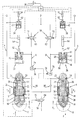
- the single drawing figure shows a schematic circuit diagram of the suspension system according to the invention, the individual components each being shown in a simplified longitudinal section.
- a suspension system according to the invention for a lift axle has two hydraulic spring cylinders 2, 4, each of which is assigned to a wheel 6, 8 of the lift axle, indicated by dashed lines.
- Each spring cylinder 2, 4 consists of a cylinder 10, in which a piston 12 is axially movable.
- the piston 12 is mechanically connected to a piston rod 14, which is guided to the outside in a manner sealed against the cylinder 10.
- the cylinder 10 is preferably connected to the wheel or the lift axle and the piston rod 14 is connected to a vehicle frame with its free, outwardly directed end.
- the piston 12 is sealed against the inner wall of the cylinder 10 by means of a circumferential seal and thereby divides two pressure spaces which can be changed in opposite directions from one another, namely a cylinder space 16 opposite the piston rod 14 and an annular space 18 surrounding the piston rod 14.
- Each spring cylinder 2, 4 has in the outside guided end area of the piston rod 14 on the one hand a first connection 20 which opens into the cylinder space 16 via an axial channel 22 of the piston rod 14, and on the other hand a second connection 24 which also opens into the annular space 18 via an axial channel 26 of the piston rod 14.
- the piston 12 has two opposing pressure surfaces, which are acted upon by hydraulic pressure, namely a larger pressure surface 28 facing the cylinder space 16 and an annular pressure surface 30 which is smaller in area and faces the annular space 18.
- each spring cylinder 2, 4, d. H. the cylinder space 16 and the annular space 18 are hydraulically separated from one another and each connected to a separate spring accumulator.
- the cylinder chamber 16 of one spring cylinder 2 is connected via the first connection 20 to a spring accumulator 32, the annular space 18 of this spring cylinder 2 via the second connection 24 to a spring accumulator 34, the cylinder chamber 16 of the other spring cylinder 4 via its first connection 20 to a spring accumulator 36 and the annular space 18 of this spring cylinder 4 via the second connection 24 with a spring accumulator 38.
- each of these spring accumulators 32 to 38 is designed as a piston accumulator with a separating piston 42 which is floating, ie freely movable, in a cylinder housing 40.
- the separating piston 42 separates a storage space 44 hydraulically connected to the respective spring cylinder 2 or 4 from one with a compressible one within the cylinder housing 40
- Medium-filled spring chamber 46 Certain pneumatic prestressing pressures of the compressible media in the spring chambers 46 result in hydraulic pressures which act on the pressure surfaces 28, 30 of the piston 12, respectively. This results in two spring cylinders 2, 4 acting in opposite directions on the piston 12, differently large piston forces F1 and F2 by acting on the pressure surfaces 28, 30 with the respective hydraulic pressure.
- Each annular space 18 of the two spring cylinders 2, 4 forms, together with its connected spring accumulator 34, 38, a closed, purely volume-controlled hydraulic circuit A
- the positions of the piston 12 of the spring cylinder 2, 4 on the one hand and of the separating piston 42 of the spring accumulator 34 on the other hand, 38 are proportional to one another, so that, according to the invention, the stroke position of the spring cylinders 6, 8 can be determined on the basis of the position of the respective separating piston 42 of the volume-controlled spring accumulator 34, 38.
- the cylinder chambers 16 of the spring cylinders 2, 4 together with the respectively connected spring accumulator 32, 36 each form a load-controlled hydraulic circuit B.
- load-controlled circuits B are preferably via a valve arrangement 50 optionally with a pressure line P or a tank line T of a hydraulic system connectable.
- the position of the separating pistons 42 of the spring accumulators 32, 36 is proportional to the respective load-dependent pressure, so that according to the invention, based on the respective position of the separating pistons 42, the load-dependent Spring accumulator 32, 36 the load-dependent pressure can be determined.
- each separating piston 42 is expediently connected to a separating piston rod 52 which is sealed off from the cylinder housing 40, and these separating piston rods 52 each act on a displacement sensor 54 which serves to position the Separating piston rods generate proportional signals.
- each separating piston 42 preferably extend through the storage space 44, so that each spring accumulator 32 to 38 is designed as a pressure transducer such that the pneumatic pressure within the spring chamber 46 is lower than the hydraulic pressure within the storage space 44. Because of the separating piston rod 52, each separating piston 42 has two differently sized pressure surfaces, namely a larger piston surface 56 facing the spring chamber 46 and an annular surface 58 smaller by the cross-section of the separating piston rod and facing the storage space 44. This described pressure difference between the pneumatic and the hydraulic pressure is particularly advantageous for the internal seal in the area of the separating piston 42.
- the valve arrangement 50 has a first pressure control valve 60 in a connection between the load-controlled circuit B of the one spring cylinder 2 and the pressure line P, a second pressure control valve 62 in a connection between the load-controlled circuit B of the other spring cylinder 4 and the pressure line P and preferably for both spring cylinders 2, 4 a common lift valve 64 in a connection between the two load-controlled circuits B and the tank line T.
- the lift valve 64 is expediently connected to each of the load-controlled circuits B via a check valve 66, these check valves opening when a flow is directed in the direction of the tank line T and blocking a reverse flow. This measure serves to decouple the two circuits B, thereby avoiding a "hydraulic short circuit".
- An electronic control device 70 in particular an electronic control device 70, is now provided for controlling the suspension system according to the invention, the displacement sensors 54 of the spring accumulators 34 to 38 being connected to signal inputs of this control device 70 in order to transmit their output signals. Furthermore, the pressure control valves 60 and 62 and the lift valve 64 of the valve arrangement 50 each have electrical or electromagnetic actuating elements 72, which are connected to control outputs of the control device 70.
- a damping valve 74, 76 is arranged between the cylinder space 16 of each spring cylinder 2, 4 and the associated spring accumulator 32, 36, wherein each damping valve 74, 76 is preferably adjustable depending on the load with regard to its damping effect.
- each damping valve 74, 76 has an adjusting device 78 which can be pressurized and which is preferably acted upon by the hydraulic, load-dependent pressure of the respective other, opposite cylinder chamber 16.
- the suspension system according to the invention has an equally good suspension behavior in practically all load conditions.
- the deflection is damped little via the damping valves 74, 76, while the respective deflection is damped more.
- the damping advantageously adjusts itself automatically to the respective load without additional sensors. Due to the connection of the adjusting devices 78 of the damping valves 74, 76 with the respectively opposite cylinder space 16, the vehicle equipped with the lifting axle is stabilized according to the invention.
- the damping valves are automatically regulated so that the pressure within the cylinder space 16 is greatly reduced on the side that rebounds.
- the load capacity of the rebounding spring cylinder is lowered very much, so that this spring cylinder can no longer support the rolling movement of the vehicle.
- the level of stabilization advantageously adjusts itself automatically both to the load and to the respective rolling speed.
- the lift valve 64 is switched to its flow position.
- the cylinder spaces 16 of the two spring cylinders 2, 4 are connected to the tank line T, so that the prevailing within the annular spaces 18, pressure generated by the spring accumulators 34, 38 "contracts" the spring cylinders 2, 4 and as a result hydraulic medium flows from the cylinder spaces 16 to the tank line T.
- the check valves 66 prevent a hydraulic short circuit from occurring between the cylinder spaces 16.
- the lift valve 64 is switched to its locked position.
- hydraulic medium is led from the pressure line P into the cylinder spaces 16 of the spring cylinders 2, 4.
- the axis is thereby lowered against the pressure of the spring accumulator 34, 38.
- the load on the spring cylinders 2, 4 increases. This has the consequence that the pressure inside the cylinder spaces 16 and within the spring accumulators 32, 36 connected to them increases.
- the stroke positions of the separating pistons 42 change, these positions being detected by the control device 70 via the separating piston rods 52 and the displacement sensors 54.
- the position of the separating pistons 42 of the volume-controlled spring accumulators 34 and 38 is also detected by the control device 70 via the separating piston rods 52 and the displacement sensors 54.
- These positions are a measure of the stroke position, ie the reference stroke position, of the spring cylinders 2, 4 at the time of the pressure increase, ie the impact of the wheels on the ground.
- This reference stroke position also indicates the path by which the main axis was deflected due to the load.
- control device 70 Based on the spring characteristic of the main axis stored in the control device 70, it is possible to do exactly from this position the load can be deduced, so that the part of the load that must be taken over by the spring cylinders 2, 4 of the lift axle can also be calculated, so that the load on the main axle is always kept constant at a predetermined, optimal value.
- the control device 70 uses this to calculate the hydraulic pressure required for this and controls the pressure control valves 60 and 62 until this required hydraulic pressure is reached. The pressure is again determined via the position of the separating pistons 42 of the spring accumulators 32 and 36.
- the adjustment process described, i. H. the "controlled load distribution" according to the invention is advantageously carried out by an operator (driver) z. B. started by actuating a start switch 80, and the process then runs - starting from the raised position of the lift axle - automatically as described. After a load change with the lift axle lowered (partial unloading / additional load), the previous lifting of the lift axle can also be included in the automatic process, so that when the start switch 80 is actuated, the lift axle is raised first and only then to adjust the load distribution (determining the current total load is reduced via the new reference stroke position). Furthermore, it can be expedient to start the setting process automatically when a change in the total load is found in the static state.
- the present invention makes it possible to automatically set an optimum load for the main axis or drive axis. This means that the drive axle always has an optimal traction effect depending on the vehicle load. Another advantage is that that too Driving behavior or suspension behavior is significantly improved.
- the load on the drive axle can be kept at least approximately constant within wide limits, regardless of the load on the vehicle.
- the present invention is not limited to the exemplary embodiment shown and described, but also encompasses all embodiments having the same effect in the sense of the invention.
- other suitable pressure sensors or displacement sensors for. B. in the area of the spring cylinder 2, 4 can be used.
Landscapes
- Engineering & Computer Science (AREA)
- Mechanical Engineering (AREA)
- Chemical & Material Sciences (AREA)
- Combustion & Propulsion (AREA)
- Transportation (AREA)
- Vehicle Body Suspensions (AREA)
Claims (17)
- Système à ressort hydropneumatique pour essieu de soulèvement associé à l'essieu principal d'un véhicule, comportant au moins deux cylindres-ressort (2, 4) qui, grâce à un agent hydraulique, agissent à l'encontre d'au moins un ressort accumulateur hydropneumatique (32, 36) qui contient un agent compressible, les faces d'appui (28, 30) respectivement en regard de pistons (12) des cylindres-ressort (2, 4) pouvant être soumises à une pression hydraulique telle que l'essieu de soulèvement puisse être soulevé et abaissé sélectivement,
caractérisé en ce que, lorsque l'essieu de soulèvement est abaissé, la pression hydraulique à l'intérieur des cylindres-ressort (2, 4) peut être réglée, au moyen des ressorts accumulateurs associés à l'essieu de soulèvement (32, 36), en fonction de l'importance de la charge totale agissant sur l'essieu principal, de manière à ce que les cylindres-ressort (2, 4) de l'essieu de soulèvement abaissé se chargent de la partie de la charge totale qui dépasse une valeur de charge déterminée optimale pour l'essieu principal, et qu'une répartition commandée de la charge entre l'essieu principal et l'essieu de soulèvement a lieu. - Système à ressort selon la revendication 1,
caractérisé en ce que la charge totale agissant sur l'essieu principal est détectée automatiquement par un dispositif de commande (70), grâce à la compression en fonction de la charge de l'essieu principal, ainsi que grâce à une courbe d'élasticité mémorisée de l'essieu principal, et en ce qu'à partir de cette charge totale ainsi détectée et de la valeur de charge optimale mémorisée pour l'essieu principal, sont déterminées la partie de la charge totale que doit prendre en charge l'essieu de soulèvement, ainsi que la pression hydraulique nécessaire à cet effet, cette pression hydraulique étant réglée dans les cylindres-ressort (2, 4). - Système à ressort selon la revendication 2,
caractérisé en ce que la compression en fonction de la charge de l'essieu principal est détectée indirectement au moyen de l'essieu de soulèvement, en abaissant l'essieu de soulèvement de sa position soulevée et en déterminant une position de levage de référence des cylindres-ressort (2, 4) de l'essieu de soulèvement dans laquelle des roues associées à l'essieu rencontrent le sol. - Système à ressort selon la revendication 3,
caractérisé en ce que la position de levage de référence des cylindres-ressort (2, 4) est déterminée par la détection d'une augmentation de la pression hydraulique dans les cylindres-ressort (2, 4) se produisant lorsque les roues rencontrent le sol, ainsi que par la détection de la position de levage associée des cylindres-ressort (2, 4). - Système à ressort selon l'une ou plusieurs des revendications 1 à 4,
caractérisé en ce que, dans chaque cylindre-ressort (2, 4), le piston (12) sépare une chambre de cylindre (16) d'une chambre annulaire (18) qui entoure la tige de piston (14), la chambre (16) et la chambre annulaire (18) étant séparées hydrauliquement entre elles et respectivement reliées à un ressort accumulateur distinct (32, 34 ; 36, 38). - Système à ressort selon la revendication 5,
caractérisé en ce que la chambre annulaire (18) et son ressort accumulateur associé (34, 38) forment un circuit hydraulique fermé (A) à volume réglable, et que la chambre (16) et son ressort accumulateur associé (32, 36) forment un circuit hydraulique (B) actionné en fonction de la charge et pouvant être sélectivement relié, au moyen d'un agencement de vannes (50), à une conduite de pression (P) ou à une conduite (T) menant au réservoir d'un système hydraulique. - Système à ressort selon l'une ou plusieurs des revendications 1 à 6,
caractérisé en ce que chaque ressort accumulateur (32 - 38) a de préférence la forme d'un ressort à piston comportant un piston séparateur (42) maintenu flottant à l'intérieur d'un boîtier de cylindre (40), le piston séparateur (42) séparant un espace d'accumulation (44) relié hydrauliquement au cylindre-ressort respectif (2, 4) d'une chambre de ressort (46) remplie d'un agent compressible. - Système à ressort selon l'une ou plusieurs des revendications 1 à 7,
caractérisé en ce que chaque ressort accumulateur (32 - 38) a de préférence la forme d'un convertisseur de pression de manière à ce que la pression pneumatique de l'agent compressible soit respectivement inférieure à la pression hydraulique. - Système à ressort selon la revendication 7 ou 8,
caractérisé en ce que le piston séparateur (42) de chaque ressort accumulateur (32 - 38) est relié à une tige (52) du piston séparateur guidée axialement à travers l'espace d'accumulation (44) et sortant de manière étanche du boîtier de cylindre (40) vers l'extérieur, de manière à ce que le piston séparateur (42) possède deux surfaces de pression de dimensions inégales, à savoir une surface de piston (56) plus grande faisant face à la chambre de ressort (46), et une surface annulaire (58) plus petite faisant face à l'espace d'accumulation (44). - Système à ressort selon l'une ou plusieurs des revendications 4 à 9,
caractérisé en ce que la pression hydraulique à l'intérieur des chambres (16) des cylindres-ressort (2, 4) est respectivement déterminée en fonction de la position du piston séparateur (42) du ressort accumulateur associé (32, 36) actionné en fonction de la charge. - Système à ressort selon l'une ou plusieurs des revendications 4 à 10,
caractérisé en ce que la position de levage des cylindres-ressort (2, 4) est respectivement déterminée en fonction de la position du piston séparateur (42) du ressort accumulateur (34, 38) actionné en fonction de la charge et relié à l'espace annulaire (18). - Système à ressort selon l'une ou plusieurs des revendications 9 à 11,
caractérisé en ce que la tige (52) du piston séparateur, de préférence de chacun des ressorts accumulateurs (32 - 38) est reliée à un indicateur de parcours (54). - Système à ressort selon l'une ou plusieurs des revendications 2 à 12,
caractérisé en ce que l'indicateur de parcours (54) et de préférence des éléments d'actionnement (72) de l'agencement de vannes (50) sont reliés à des entrées de signaux ou sorties de commande du dispositif de commande (70). - Système à ressort selon l'une ou plusieurs des revendications 6 à 13,
caractérisé en ce que l'agencement de vannes (50) comporte, dans une liaison entre le circuit actionné en fonction de la charge (B) de l'un des cylindres-ressort (2) et la conduite de pression (P), une première vanne de commande de la pression (60), et, dans une liaison entre le circuit actionné en fonction de la charge (B) de l'autre cylindre-ressort (4) et la conduite de pression (P), une deuxième vanne de commande de la pression (62), ainsi que, de préférence, une vanne de soulèvement (64) commune aux deux cylindres-ressort (2, 4) et agencée dans une liaison entre les deux circuits actionnés en fonction de la charge (B) et la conduite menant au réservoir (T). - Système à ressort selon la revendication 14,
caractérisé en ce que la vanne de soulèvement (64) est reliée à chacun des circuits actionnés en fonction de la charge (B) par un clapet anti-retour (66) qui s'ouvre pour un flux dirigé vers la conduite menant au réservoir (T) et se ferme pour un flux circulant dans la direction inverse. - Système à ressort selon l'une ou plusieurs des revendications 5 à 15,
caractérisé en ce que, entre l'espace de cylindre (16) de chaque cylindre-ressort (2, 4) et le ressort accumulateur associé (32, 36), il est prévu une soupape d'amortissement (74, 76), l'effet d'amortissement de chaque soupape (74, 76) pouvant être réglé en fonction de la charge. - Système à ressort selon la revenedication 16,
caractérisé en ce que chaque soupape d'amortissement (74, 76) comporte, pour le réglage de son effet d'amortissement, un moyen de réglage (78) pouvant être soumis à une pression, de préférence, la pression hydraulique, fonction de la charge, de l'autre chambre de cylindre (16) respectivement située en regard.
Applications Claiming Priority (2)
| Application Number | Priority Date | Filing Date | Title |
|---|---|---|---|
| DE4127801 | 1991-08-22 | ||
| DE4127801A DE4127801A1 (de) | 1991-08-22 | 1991-08-22 | Hydropneumatisches federungssystem fuer eine fahrzeug-liftachse |
Publications (2)
| Publication Number | Publication Date |
|---|---|
| EP0529320A1 EP0529320A1 (fr) | 1993-03-03 |
| EP0529320B1 true EP0529320B1 (fr) | 1996-06-19 |
Family
ID=6438848
Family Applications (1)
| Application Number | Title | Priority Date | Filing Date |
|---|---|---|---|
| EP92112760A Expired - Lifetime EP0529320B1 (fr) | 1991-08-22 | 1992-07-25 | Système de ressort oléopneumatique pour l'essieu relevable d'un véhicule |
Country Status (3)
| Country | Link |
|---|---|
| EP (1) | EP0529320B1 (fr) |
| AT (1) | ATE139491T1 (fr) |
| DE (2) | DE4127801A1 (fr) |
Families Citing this family (11)
| Publication number | Priority date | Publication date | Assignee | Title |
|---|---|---|---|---|
| DE4311243C2 (de) * | 1993-04-06 | 1995-12-07 | Daimler Benz Ag | Hubvorrichtung für eine Liftachse eines Lastfahrzeuges |
| DE10106706A1 (de) * | 2001-02-14 | 2002-09-26 | Hydac Technology Gmbh | Federungssystem, insbesondere für eine Arbeitsmaschine |
| DE10107631B4 (de) * | 2001-02-15 | 2007-04-05 | Carl Freudenberg Kg | Verfahren und Einrichtung zur Steuerung des Federungsverhaltens bei Fahrzeugen mit hydropneumatischen Federungseinrichtungen und stark veränderbaren Achslastverhältnissen |
| US8151953B2 (en) | 2004-04-08 | 2012-04-10 | Samsung Electronics Co., Ltd. | Suspension and damping device for motor vehicles |
| DE202004005623U1 (de) * | 2004-04-08 | 2005-08-11 | Hemscheidt Fahrwerktechnik Gmbh & Co. Kg | Federungs- und Dämpfungseinrichtung für Kraftfahrzeuge |
| US7472914B2 (en) | 2005-02-28 | 2009-01-06 | Anderson Brian K | Suspension system |
| DE202005011439U1 (de) | 2005-07-18 | 2006-11-23 | Hemscheidt Fahrwerktechnik Gmbh & Co. Kg | Federungseinrichtung für Kraftfahrzeuge |
| FR2919571B1 (fr) * | 2007-07-30 | 2010-02-26 | Actm | Vehicule routier a essieu mobile descendant automatiquement en cas de depassement de la charge maximale par essieu |
| DE102008017702B4 (de) * | 2008-04-08 | 2011-03-31 | Knorr-Bremse Systeme für Nutzfahrzeuge GmbH | Achshebevorrichtung und Verfahren zum Anheben einer Achse |
| SE538947C2 (sv) * | 2013-03-07 | 2017-02-28 | Vm Trailer Ab | Anordning vid hjulförsett fordon som innefattar en axellyft |
| DE102013008656A1 (de) * | 2013-05-18 | 2014-11-20 | Wabco Gmbh | Verfahren zur Traktionsregelung eines pneumatisch gefederten Fahrzeugs und Luftfederungssystem zur Durchführung des Verfahrens |
Family Cites Families (11)
| Publication number | Priority date | Publication date | Assignee | Title |
|---|---|---|---|---|
| DE2020292A1 (de) * | 1970-04-25 | 1971-11-18 | Bosch Gmbh Robert | Abstuetzsystem fuer Kraftfahrzeuge |
| DE3330368A1 (de) * | 1983-08-23 | 1985-03-14 | Mannesmann Rexroth GmbH, 8770 Lohr | Federanordnung mit niveauregulierung fuer fahrzeuge |
| FR2621536B1 (fr) * | 1987-10-09 | 1990-02-02 | Renault Vehicules Ind | Dispositif de commande notamment de relevage et de descente d'un essieu auxiliaire suspendu de vehicule |
| DD286713A7 (de) * | 1988-09-19 | 1991-02-07 | Fz F. Mechanisierung U. Energieanwendung,De | Regelvorrichtung zur entlastung und zum aushub von zusatzachsen an landwirtschaftlichen maschinen |
| DE3902743C1 (en) * | 1989-01-31 | 1990-07-26 | Daimler-Benz Aktiengesellschaft, 7000 Stuttgart, De | Active wheel or axle support |
| DE3934385A1 (de) * | 1989-10-14 | 1991-04-18 | Hemscheidt Maschf Hermann | Hydropneumatisches federungssystem |
| DE4008831C2 (de) * | 1990-03-20 | 1993-11-25 | Hemscheidt Maschf Hermann | Hydropneumatisches Federungssystem |
| DE3936034A1 (de) * | 1989-10-28 | 1991-05-02 | Hemscheidt Maschf Hermann | Hydropneumatisches federungssystem |
| EP0425885B1 (fr) * | 1989-10-28 | 1994-07-20 | HEMSCHEIDT FAHRWERKTECHNIK GmbH & Co. | Système à ressort hydropneumatique |
| DE4014441C2 (de) * | 1989-12-23 | 1995-08-03 | Hemscheidt Fahrwerktech Gmbh | Nivelliersystem für Kfz-Federungssysteme |
| DE9103359U1 (de) * | 1990-03-20 | 1991-06-20 | Hermann Hemscheidt Maschinenfabrik Gmbh & Co, 5600 Wuppertal | Hydropneumatisches Federungssystem für Radfahrzeuge |
-
1991
- 1991-08-22 DE DE4127801A patent/DE4127801A1/de not_active Withdrawn
-
1992
- 1992-07-25 EP EP92112760A patent/EP0529320B1/fr not_active Expired - Lifetime
- 1992-07-25 DE DE59206601T patent/DE59206601D1/de not_active Expired - Fee Related
- 1992-07-25 AT AT92112760T patent/ATE139491T1/de active
Also Published As
| Publication number | Publication date |
|---|---|
| DE59206601D1 (de) | 1996-07-25 |
| ATE139491T1 (de) | 1996-07-15 |
| EP0529320A1 (fr) | 1993-03-03 |
| DE4127801A1 (de) | 1993-02-25 |
Similar Documents
| Publication | Publication Date | Title |
|---|---|---|
| EP0425885B1 (fr) | Système à ressort hydropneumatique | |
| DE4017223C2 (fr) | ||
| DE3874384T2 (de) | System zum erzeugen eines mit dem betriebszustand eines kraftfahrzeugs veraenderlichen hydraulischen druckes. | |
| EP0052782B1 (fr) | Système de suspension pour véhicules | |
| DE3788594T2 (de) | Aktiv geregeltes Fahrzeugaufhängungssystem mit regelbarer Rollstabilität. | |
| DE68918334T2 (de) | Antirollregelungssystem für aktive Fahrzeugaufhängungen mit von der Fahrbahnreibung abhängigen veränderlichen Regelcharakteristiken. | |
| DE68908484T2 (de) | Antirollregelung für aktiv geregelte Fahrzeugaufhängungssysteme mit erhöhter Fähigkeit zur Ermittlung der Rollneigung. | |
| DE3414257A1 (de) | Vorrichtung zum steuern der federhaerte eines fahrzeugs ii | |
| EP0495442B1 (fr) | Système de suspension hydropneumatique notamment pour cabine de conducteur de véhicules utilitaires | |
| EP0389828A2 (fr) | Système de suspension hydropneumatique | |
| EP0351537B1 (fr) | Système à ressort et amortisseur pour véhicules | |
| DE4019732A1 (de) | Vorrichtung zur steuerung aktiver radaufhaengungen von fahrzeugen | |
| EP0367949A2 (fr) | Système de suspension pour véhicules | |
| DE3910030C2 (de) | Radaufhängung für Fahrzeuge | |
| DE68908846T2 (de) | Hydraulisches Fahrzeugaufhängungssystem. | |
| EP1094959B1 (fr) | Systeme de regulation de pression | |
| DE4024306A1 (de) | Steuervorrichtung zur stellungsaenderung fuer aktive aufhaengungssysteme von kraftfahrzeugen | |
| EP0529320A1 (fr) | Système de ressort oléopneumatique pour l'essieu relevable d'un véhicule | |
| DE102006025826B4 (de) | Selbstpumpendes hydropneumatisches Federbein | |
| DE4008831C2 (de) | Hydropneumatisches Federungssystem | |
| DE3934385A1 (de) | Hydropneumatisches federungssystem | |
| DE3936034A1 (de) | Hydropneumatisches federungssystem | |
| DE4004204C2 (de) | Hydropneumatisches Federungssystem mit Kippausgleich | |
| DE3936987A1 (de) | Hydropneumatisches federungssystem | |
| DE102007033527A1 (de) | Fahrzeug mit drei Achsen und einer Vorrichtung zur Steuerung oder Regelung der Achs- bzw. Radlasten |
Legal Events
| Date | Code | Title | Description |
|---|---|---|---|
| PUAI | Public reference made under article 153(3) epc to a published international application that has entered the european phase |
Free format text: ORIGINAL CODE: 0009012 |
|
| AK | Designated contracting states |
Kind code of ref document: A1 Designated state(s): AT BE CH DE ES FR GB IT LI NL PT SE |
|
| 17P | Request for examination filed |
Effective date: 19930224 |
|
| RAP1 | Party data changed (applicant data changed or rights of an application transferred) |
Owner name: HEMSCHEIDT FAHRWERKTECHNIK GMBH & CO. KG |
|
| 17Q | First examination report despatched |
Effective date: 19940630 |
|
| RAP3 | Party data changed (applicant data changed or rights of an application transferred) |
Owner name: HEMSCHEIDT FAHRWERKTECHNIK GMBH & CO. |
|
| GRAH | Despatch of communication of intention to grant a patent |
Free format text: ORIGINAL CODE: EPIDOS IGRA |
|
| GRAH | Despatch of communication of intention to grant a patent |
Free format text: ORIGINAL CODE: EPIDOS IGRA |
|
| GRAA | (expected) grant |
Free format text: ORIGINAL CODE: 0009210 |
|
| AK | Designated contracting states |
Kind code of ref document: B1 Designated state(s): AT BE CH DE ES FR GB IT LI NL PT SE |
|
| PG25 | Lapsed in a contracting state [announced via postgrant information from national office to epo] |
Ref country code: IT Free format text: LAPSE BECAUSE OF FAILURE TO SUBMIT A TRANSLATION OF THE DESCRIPTION OR TO PAY THE FEE WITHIN THE PRE;WARNING: LAPSES OF ITALIAN PATENTS WITH EFFECTIVE DATE BEFORE 2007 MAY HAVE OCCURRED AT ANY TIME BEFORE 2007. THE CORRECT EFFECTIVE DATE MAY BE DIFFERENT FROM THE ONE RECORDED.SCRIBED TIME-LIMIT Effective date: 19960619 Ref country code: GB Effective date: 19960619 Ref country code: ES Free format text: THE PATENT HAS BEEN ANNULLED BY A DECISION OF A NATIONAL AUTHORITY Effective date: 19960619 |
|
| REF | Corresponds to: |
Ref document number: 139491 Country of ref document: AT Date of ref document: 19960715 Kind code of ref document: T |
|
| REF | Corresponds to: |
Ref document number: 59206601 Country of ref document: DE Date of ref document: 19960725 |
|
| PG25 | Lapsed in a contracting state [announced via postgrant information from national office to epo] |
Ref country code: BE Effective date: 19960731 Ref country code: CH Effective date: 19960731 Ref country code: LI Effective date: 19960731 |
|
| ET | Fr: translation filed | ||
| PG25 | Lapsed in a contracting state [announced via postgrant information from national office to epo] |
Ref country code: PT Effective date: 19960919 |
|
| GBV | Gb: ep patent (uk) treated as always having been void in accordance with gb section 77(7)/1977 [no translation filed] |
Effective date: 19960619 |
|
| REG | Reference to a national code |
Ref country code: CH Ref legal event code: PL |
|
| PLBE | No opposition filed within time limit |
Free format text: ORIGINAL CODE: 0009261 |
|
| STAA | Information on the status of an ep patent application or granted ep patent |
Free format text: STATUS: NO OPPOSITION FILED WITHIN TIME LIMIT |
|
| 26N | No opposition filed | ||
| PGFP | Annual fee paid to national office [announced via postgrant information from national office to epo] |
Ref country code: AT Payment date: 20000710 Year of fee payment: 9 |
|
| PGFP | Annual fee paid to national office [announced via postgrant information from national office to epo] |
Ref country code: SE Payment date: 20000717 Year of fee payment: 9 |
|
| PGFP | Annual fee paid to national office [announced via postgrant information from national office to epo] |
Ref country code: DE Payment date: 20000912 Year of fee payment: 9 |
|
| PGFP | Annual fee paid to national office [announced via postgrant information from national office to epo] |
Ref country code: FR Payment date: 20010523 Year of fee payment: 10 |
|
| PG25 | Lapsed in a contracting state [announced via postgrant information from national office to epo] |
Ref country code: AT Free format text: LAPSE BECAUSE OF NON-PAYMENT OF DUE FEES Effective date: 20010725 |
|
| PG25 | Lapsed in a contracting state [announced via postgrant information from national office to epo] |
Ref country code: SE Free format text: LAPSE BECAUSE OF NON-PAYMENT OF DUE FEES Effective date: 20010726 |
|
| EUG | Se: european patent has lapsed |
Ref document number: 92112760.1 |
|
| PG25 | Lapsed in a contracting state [announced via postgrant information from national office to epo] |
Ref country code: DE Free format text: LAPSE BECAUSE OF NON-PAYMENT OF DUE FEES Effective date: 20020601 |
|
| PG25 | Lapsed in a contracting state [announced via postgrant information from national office to epo] |
Ref country code: FR Free format text: LAPSE BECAUSE OF NON-PAYMENT OF DUE FEES Effective date: 20030331 |
|
| REG | Reference to a national code |
Ref country code: FR Ref legal event code: ST |
|
| PGFP | Annual fee paid to national office [announced via postgrant information from national office to epo] |
Ref country code: NL Payment date: 20110715 Year of fee payment: 20 |
|
| REG | Reference to a national code |
Ref country code: NL Ref legal event code: V4 Effective date: 20120725 |