EP0426237B1 - Procédé de détection de l'insuffisance de vide dans les tubes de télévision - Google Patents
Procédé de détection de l'insuffisance de vide dans les tubes de télévision Download PDFInfo
- Publication number
- EP0426237B1 EP0426237B1 EP90202833A EP90202833A EP0426237B1 EP 0426237 B1 EP0426237 B1 EP 0426237B1 EP 90202833 A EP90202833 A EP 90202833A EP 90202833 A EP90202833 A EP 90202833A EP 0426237 B1 EP0426237 B1 EP 0426237B1
- Authority
- EP
- European Patent Office
- Prior art keywords
- tube
- voltage
- tubes
- vacuum
- procedure
- Prior art date
- Legal status (The legal status is an assumption and is not a legal conclusion. Google has not performed a legal analysis and makes no representation as to the accuracy of the status listed.)
- Expired - Lifetime
Links
- 238000000034 method Methods 0.000 title claims description 13
- 238000004519 manufacturing process Methods 0.000 claims description 7
- 238000005247 gettering Methods 0.000 claims description 4
- 238000009413 insulation Methods 0.000 description 4
- 238000001514 detection method Methods 0.000 description 2
- 238000005259 measurement Methods 0.000 description 2
- 230000003071 parasitic effect Effects 0.000 description 1
- 230000001172 regenerating effect Effects 0.000 description 1
Images
Classifications
-
- H—ELECTRICITY
- H01—ELECTRIC ELEMENTS
- H01J—ELECTRIC DISCHARGE TUBES OR DISCHARGE LAMPS
- H01J9/00—Apparatus or processes specially adapted for the manufacture, installation, removal, maintenance of electric discharge tubes, discharge lamps, or parts thereof; Recovery of material from discharge tubes or lamps
- H01J9/42—Measurement or testing during manufacture
Definitions
- the invention relates to a method for selecting television picture tubes with too low a vacuum during manufacture.
- it is important to discard all picture tubes with too low a vacuum in good time during the production process so that they are not changed by further production steps, e.g. gettering, in such a way that repairing / regenerating these tubes is made difficult or impossible becomes.
- the invention is therefore based on the object of designing a method of the type mentioned at the outset in such a way that it works simply and safely and the selection of the tubes is practically not falsified by insulation currents.
- This object is achieved according to the invention in that between the anode (g4) and a second electrode (g3) of the tube, a DC voltage which rises continuously from a low value to a maximum value is applied, the rise of which is stopped when a (spark) or discharge) current flows and the associated value of the DC voltage is evaluated as a criterion for the selection of the tube.
- the insulation currents within the tube base are not included in the measurement result, and the measurement circuit can be constructed much more simply, since it is not a small current that has to be measured at a constant applied voltage, but only the point in time (and the associated voltage value) to which a current begins to flow in the tube.
- the focusing electrode (g3) is preferably used as the second electrode.
- the second and all further electrodes are preferably connected to ground potential.
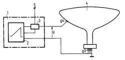
- the figure shows schematically an apparatus for performing the method according to the invention and a television picture tube connected to it.
- the device 1 consists of a voltage generator 2 which generates a DC voltage which rises continuously from a low value to a maximum value and which is applied between the anode (g4) and the focusing electrode (g3) of the tube 4.
- the focusing electrode is connected to earth potential together with all other electrodes (g3) filtered out on the base of the tube.
- a detection circuit 3 is inserted, which emits a signal in its output S as soon as a current flows in the tube between the anode (g4) and the focusing electrode (g3) and causes the voltage U does not continue to rise.
- the voltage U of the voltage generator 2 rises to its maximum value at a rate of approximately 3 kV / sec.
- the voltage U generated by the voltage generator 2 is set such that, at its maximum value (for example 20 kV) in a tube with a good vacuum, no current flows between the anode (g4) and the focusing electrode (g3), which current in the detection circuit 3 leads to a signal at its output S.
- the vacuum in the tube 4 is below a predetermined value (before gettering) of approximately 1 to 20 Pa, a current flows at a value of the voltage which is below the maximum value, which leads to a signal at the selection output S, which then triggers that this tube with bad vacuum is first removed from the production process.
- a predetermined value before gettering
- a current flows at a value of the voltage which is below the maximum value, which leads to a signal at the selection output S, which then triggers that this tube with bad vacuum is first removed from the production process.
Landscapes
- Engineering & Computer Science (AREA)
- Manufacturing & Machinery (AREA)
- Manufacture Of Electron Tubes, Discharge Lamp Vessels, Lead-In Wires, And The Like (AREA)
- Vessels, Lead-In Wires, Accessory Apparatuses For Cathode-Ray Tubes (AREA)
Claims (4)
- Procédé de sélection de tubes images de télévision à vide insuffisant, au cours de la fabrication, caractérisé en ce qu'on applique entre l'anode (g4) et une deuxième électrode (g3) du tube, une tension continue croissant continuellement d'une valeur basse jusqu'à une valeur maximum, on arrête cette croissance lorsque dans le tube passe un courant de décharge et on évalue la valeur correspondante de la tension continue en tant que critère pour la sélection du tube.
- Procédé selon la revendication 1, caractérisé en ce qu'on utilise comme deuxième électrode l'électrode de focalisation (g3).
- Procédé selon la revendication 1 ou 2, caractérisé en ce que l'électrode de focalisation (g3) et toutes les autres électrodes (en dehors de l'anode) sont mises au potentiel de terre.
- Procédé selon l'une quelconque des revendications précédentes, caractérisé en ce qu'on le réalise avant de soumettre les tubes à une sorption par getter.
Applications Claiming Priority (2)
| Application Number | Priority Date | Filing Date | Title |
|---|---|---|---|
| DE3936015 | 1989-10-28 | ||
| DE3936015A DE3936015A1 (de) | 1989-10-28 | 1989-10-28 | Verfahren zum selektieren von fernsehbildroehren mit zu niedrigem vakuum |
Publications (3)
| Publication Number | Publication Date |
|---|---|
| EP0426237A2 EP0426237A2 (fr) | 1991-05-08 |
| EP0426237A3 EP0426237A3 (en) | 1991-11-21 |
| EP0426237B1 true EP0426237B1 (fr) | 1994-05-18 |
Family
ID=6392473
Family Applications (1)
| Application Number | Title | Priority Date | Filing Date |
|---|---|---|---|
| EP90202833A Expired - Lifetime EP0426237B1 (fr) | 1989-10-28 | 1990-10-24 | Procédé de détection de l'insuffisance de vide dans les tubes de télévision |
Country Status (4)
| Country | Link |
|---|---|
| US (1) | US5083957A (fr) |
| EP (1) | EP0426237B1 (fr) |
| JP (1) | JPH03165422A (fr) |
| DE (2) | DE3936015A1 (fr) |
Families Citing this family (3)
| Publication number | Priority date | Publication date | Assignee | Title |
|---|---|---|---|---|
| DE69304499T2 (de) * | 1992-12-17 | 1997-03-13 | Philips Electronics Nv | Verfahren zum Aushärten eines Filmes |
| DE19526394A1 (de) * | 1995-07-19 | 1997-01-23 | Siemens Ag | Verfahren zum Vakuumnachweis in betriebsmäßig eingebauten Vakuumschaltröhren |
| US6722184B2 (en) | 2001-09-13 | 2004-04-20 | Guide Corporation | Apparatus and method for pressurized oxygen bulb curing and testing |
Family Cites Families (5)
| Publication number | Priority date | Publication date | Assignee | Title |
|---|---|---|---|---|
| US1592364A (en) * | 1921-04-26 | 1926-07-13 | Western Electric Co | Ionization manometer |
| SU656126A1 (ru) * | 1976-06-23 | 1979-04-05 | Рязанский Радиотехнический Институт | Схема дл измерени давлени в отпа нных электровакуумных приборах |
| US4052776A (en) * | 1976-09-30 | 1977-10-11 | Zenith Radio Corporation | Method of spot-knocking an electron gun assembly in a color television picture tube |
| JPS6273526A (ja) * | 1985-09-27 | 1987-04-04 | Hitachi Ltd | けい光ランプの封入ガス圧力測定方法 |
| US4720652A (en) * | 1987-01-20 | 1988-01-19 | Cooper Industries, Inc. | Sealed beam headlamp and method for testing its serviceability |
-
1989
- 1989-10-28 DE DE3936015A patent/DE3936015A1/de not_active Withdrawn
-
1990
- 1990-10-18 US US07/599,784 patent/US5083957A/en not_active Expired - Lifetime
- 1990-10-24 DE DE59005734T patent/DE59005734D1/de not_active Expired - Fee Related
- 1990-10-24 EP EP90202833A patent/EP0426237B1/fr not_active Expired - Lifetime
- 1990-10-25 JP JP2286008A patent/JPH03165422A/ja active Pending
Also Published As
| Publication number | Publication date |
|---|---|
| EP0426237A3 (en) | 1991-11-21 |
| EP0426237A2 (fr) | 1991-05-08 |
| DE3936015A1 (de) | 1991-05-02 |
| US5083957A (en) | 1992-01-28 |
| DE59005734D1 (de) | 1994-06-23 |
| JPH03165422A (ja) | 1991-07-17 |
Similar Documents
| Publication | Publication Date | Title |
|---|---|---|
| EP0104577B1 (fr) | Procédé pour tester sans contact un objet, particulièrement un microcâblage avec une sonde à rayons corpusculaires | |
| DE10011294B4 (de) | Verfahren zum Betrieb einer Röntgenröhre | |
| EP0508062B1 (fr) | Méthode et dispositif pour tester un arrangement de conducteurs électriques | |
| DE3635133C2 (fr) | ||
| DE3401749A1 (de) | Roentgendiagnostikeinrichtung mit einer roentgenroehre | |
| DE2606395C3 (de) | Verfahren und Vorrichtung zur Überwachung des elektrischen Verhaltens einer stromstarken Glimmentladung | |
| CH660658A5 (de) | Anordnung zum erzeugen einer veraenderbaren vorspannung fuer eine roentgenroehre. | |
| EP0426237A2 (fr) | Procédé de détection de l'insuffisance de vide dans les tubes de télévision | |
| DE4211251C1 (fr) | ||
| EP0472938A2 (fr) | Dispositif pour tester et réparer un circuit intégré | |
| DE2431401A1 (de) | Frequenzempfindliche vorionisationseinrichtung | |
| DE2207546A1 (de) | Verfahren zum pruefen des elektrischen durchganges | |
| DE3121311C2 (fr) | ||
| DE202004020402U1 (de) | Vorrichtung zur Erkennung von Störlichtbögen | |
| EP0232790A1 (fr) | Procédé et dispositif pour mesurer des signaux en fonction du temps avec une sonde à rayon corpusculaire | |
| DE2249365B2 (de) | Röntgengerät mit einer der Glühkathode der Röntgenröhre vorgelagerten Rechteckblende, an der eine einstellbare Spannung liegt | |
| DE900876C (de) | Anordnung zur Wiedergabe von Haeufigkeitskurven mittels einer Braunschen Roehre | |
| DE2436622C2 (de) | Bildwandler- oder Bildverstärkerröhre | |
| EP0060337B1 (fr) | Microscope électronique à balayage | |
| DE683751C (de) | Verfahren zur Erzeugung von Ablenkspannungen bzw. -stroemen mit Hilfe eines Sekundaerelektronenverstaerkers | |
| DE102020112035B3 (de) | Verfahren zum Erkennen eines Lichtbogens in einem Bordnetz mittels Sichtbarkeitsgraphen, Steuereinrichtung sowie Bordnetz | |
| DE833372C (de) | Schaltung fuer selbsttaetige Signalsysteme | |
| DE341562C (de) | Gas enthaltender oder evakuierter Detektor fuer Strahlenenergie mit einer Kathode und einer Anode | |
| DE2545849A1 (de) | Verfahren zum pruefen der hochspannungsfestigkeit und vorrichtung zur durchfuehrung des verfahrens | |
| DE1267880B (de) | Schaltungsanordnung fuer einen Lecksucher mit akustischer Anzeige |
Legal Events
| Date | Code | Title | Description |
|---|---|---|---|
| PUAI | Public reference made under article 153(3) epc to a published international application that has entered the european phase |
Free format text: ORIGINAL CODE: 0009012 |
|
| AK | Designated contracting states |
Kind code of ref document: A2 Designated state(s): DE FR GB IT |
|
| PUAL | Search report despatched |
Free format text: ORIGINAL CODE: 0009013 |
|
| AK | Designated contracting states |
Kind code of ref document: A3 Designated state(s): DE FR GB IT |
|
| 17P | Request for examination filed |
Effective date: 19920521 |
|
| 17Q | First examination report despatched |
Effective date: 19930625 |
|
| GRAA | (expected) grant |
Free format text: ORIGINAL CODE: 0009210 |
|
| AK | Designated contracting states |
Kind code of ref document: B1 Designated state(s): DE FR GB IT |
|
| REF | Corresponds to: |
Ref document number: 59005734 Country of ref document: DE Date of ref document: 19940623 |
|
| ITF | It: translation for a ep patent filed | ||
| GBT | Gb: translation of ep patent filed (gb section 77(6)(a)/1977) |
Effective date: 19940801 |
|
| ET | Fr: translation filed | ||
| PLBE | No opposition filed within time limit |
Free format text: ORIGINAL CODE: 0009261 |
|
| STAA | Information on the status of an ep patent application or granted ep patent |
Free format text: STATUS: NO OPPOSITION FILED WITHIN TIME LIMIT |
|
| ITPR | It: changes in ownership of a european patent |
Owner name: CAMBIO RAGIONE SOCIALE;PHILIPS ELECTRONICS N.V. |
|
| 26N | No opposition filed | ||
| REG | Reference to a national code |
Ref country code: FR Ref legal event code: CD |
|
| PGFP | Annual fee paid to national office [announced via postgrant information from national office to epo] |
Ref country code: GB Payment date: 19970930 Year of fee payment: 8 |
|
| PGFP | Annual fee paid to national office [announced via postgrant information from national office to epo] |
Ref country code: FR Payment date: 19971021 Year of fee payment: 8 |
|
| PGFP | Annual fee paid to national office [announced via postgrant information from national office to epo] |
Ref country code: DE Payment date: 19971219 Year of fee payment: 8 |
|
| REG | Reference to a national code |
Ref country code: FR Ref legal event code: CD |
|
| PG25 | Lapsed in a contracting state [announced via postgrant information from national office to epo] |
Ref country code: GB Free format text: LAPSE BECAUSE OF NON-PAYMENT OF DUE FEES Effective date: 19981024 |
|
| GBPC | Gb: european patent ceased through non-payment of renewal fee |
Effective date: 19981024 |
|
| PG25 | Lapsed in a contracting state [announced via postgrant information from national office to epo] |
Ref country code: FR Free format text: LAPSE BECAUSE OF NON-PAYMENT OF DUE FEES Effective date: 19990630 |
|
| REG | Reference to a national code |
Ref country code: FR Ref legal event code: ST |
|
| PG25 | Lapsed in a contracting state [announced via postgrant information from national office to epo] |
Ref country code: DE Free format text: LAPSE BECAUSE OF NON-PAYMENT OF DUE FEES Effective date: 19990803 |
|
| PG25 | Lapsed in a contracting state [announced via postgrant information from national office to epo] |
Ref country code: IT Free format text: LAPSE BECAUSE OF NON-PAYMENT OF DUE FEES Effective date: 20051024 |