EP0426281A2 - Verbesserte Zähler-/Zeitgeberverhältnisse in einem Logikanalysator - Google Patents
Verbesserte Zähler-/Zeitgeberverhältnisse in einem Logikanalysator Download PDFInfo
- Publication number
- EP0426281A2 EP0426281A2 EP90309247A EP90309247A EP0426281A2 EP 0426281 A2 EP0426281 A2 EP 0426281A2 EP 90309247 A EP90309247 A EP 90309247A EP 90309247 A EP90309247 A EP 90309247A EP 0426281 A2 EP0426281 A2 EP 0426281A2
- Authority
- EP
- European Patent Office
- Prior art keywords
- counter
- timer
- trigger
- count
- cycle
- Prior art date
- Legal status (The legal status is an assumption and is not a legal conclusion. Google has not performed a legal analysis and makes no representation as to the accuracy of the status listed.)
- Withdrawn
Links
Images


Classifications
-
- G—PHYSICS
- G01—MEASURING; TESTING
- G01R—MEASURING ELECTRIC VARIABLES; MEASURING MAGNETIC VARIABLES
- G01R31/00—Arrangements for testing electric properties; Arrangements for locating electric faults; Arrangements for electrical testing characterised by what is being tested not provided for elsewhere
- G01R31/28—Testing of electronic circuits, e.g. by signal tracer
- G01R31/317—Testing of digital circuits
- G01R31/3177—Testing of logic operation, e.g. by logic analysers
-
- G—PHYSICS
- G06—COMPUTING OR CALCULATING; COUNTING
- G06F—ELECTRIC DIGITAL DATA PROCESSING
- G06F11/00—Error detection; Error correction; Monitoring
- G06F11/22—Detection or location of defective computer hardware by testing during standby operation or during idle time, e.g. start-up testing
- G06F11/25—Testing of logic operation, e.g. by logic analysers
-
- G—PHYSICS
- G06—COMPUTING OR CALCULATING; COUNTING
- G06F—ELECTRIC DIGITAL DATA PROCESSING
- G06F11/00—Error detection; Error correction; Monitoring
- G06F11/30—Monitoring
- G06F11/34—Recording or statistical evaluation of computer activity, e.g. of down time, of input/output operation ; Recording or statistical evaluation of user activity, e.g. usability assessment
Definitions
- This invention relates to the field of digital data acquisition and logic analysis, and more particularly to the field of counting and timing intervals in a logic analyzer or other digital data acquisition instrument.
- Logic analyzers are digital data acquisition instruments that allow a user to acquire and analyze digital data from a large number of logic signals, such as the address, data, and control lines of a microprocessor.
- the logic analyzer periodically compares each of these logic signals to a reference threshold in order to determine in which logic state, high or low, each of the lines is.
- Trigger sections allow operators to specify when in time they would like to acquire data, i.e., which data they are interested in. This is necessary because even the largest acquisition memories are quickly filled by all the data occurring in a fast electronic system.
- the trigger is the most important reference time in a logic analyzer, since it initiates the sequence of activities associated with data acquisition and is frequently the reference time for other measurements.
- the operator specifies a sequence of events or particular conditions, which, if it occurs, indicate at this is the data that the operator is interested in. While the logic analyzer is running and waiting for the specified trigger conditions to occur, the digital data from the system under test is sent to a circular memory, which may be overwritten and refilled many times before the trigger occurs indicating that the interval of interest has been reached.
- the flow of new data into the circular memory is interrupted and the data present is saved.
- This storage of digital data can occur immediately upon the occurrence of the trigger condition or after a variable delay. If the writing to memory is stopped immediately, the memory contains data reflecting the activity that occurred prior to the trigger event, i.e. "pretrigger" data. Conversely, if the memory is allowed to keep filling for its whole length after the trigger condition occurs, the contents of the memory reflect entirely the activity that occurred immediately after the trigger event, i.e., "posttrigger" data. Typically, any one of a number of combinations of pretrigger and posttrigger data storage can be selected. Which combination a user chooses is dictated by the problem he is trying to solve and which conditions in the temporal vicinity of the problem can be identified well enough to program the trigger machine.
- the trigger sections of some logic analyzers also contain one or more counter/timers. These allow the trigger condition to be specified in terms of a number of occurrences of some event or in terms of a time.
- a timer can be used to measure the interval between two events and the trigger section can be programmed to produce a trigger when this interval exceeds a certain value.
- the counter/timer can be made to count every occurrence of event A and to reset upon the occurrence of event B, with the trigger section programmed to produce a trigger if the count of A occurrences reaches a particular value.
- Logic analyzers of the prior art have generally terminated all timing and counting activity upon the occurrence of the trigger. This is because in many logic analyzers the counter/timer, if there is one, is an integral part of the trigger section and therefore cease all activity, including a current measurement, when a trigger signal is produced.
- An example of an instrument of this type is the 1240 Logic Analyzer made by Tektronix, Inc. of Beaverton, Oregon.
- some prior art logic analyzers have a trigger state machine that continues to run and provide information to the rest of a system after generating a local trigger that stops a local acquisition memory.
- An example of an instrument of this type is the 92A16 Logic Analyzer of the Digital Analysis System 9200, also made by Tektronix.
- the results of that measurement are not displayed to the user; only the information that the counter/timer produced the trigger is displayed.
- the present invention is a logic analyzer in which a counter/timer is used as part of the trigger section resources and yet remains active to complete any on-going measurement after a trigger occurs.
- the occurrence of a trigger from a trigger state machine puts the counter/timer control logic in a mode that prevents future measurements from starting, but allows the current measurement to continue to completion and the result to be saved and presented to a user.
- the counter/timer can be used to generate a trigger and then continue the current measurement to completion and save it, providing meaningful results about the measurement that caused the trigger.
- a logic analyser embodying the present invention may have an internal clock rate of 200 MHz, but nonetheless sample and acquire digital data at 400 MHz by using both edges of its internal clock for data sampling. As the data moves into the logic analyzer, a pair of successive samples are processed together at 200 MHz. The most recently acquired sample of the two is referred as the "young" data and the older of the two is referred to as the “middle” data. “Old” data is the young data from the previous sample pair.
- Event recognizers monitor the young and middle data, for a total of four event recognizers, A-young, A-middle, B-young, and B-middle.
- Event recognizers can identify words, glitches, unstable data, ranges, transitions into or out of a particular state, and/or other signal characteristics.
- Word recognition determines whether or not an ANDed combination of "1"s, "0"s, "don't care”s, and "in-between”s is present on specified signal lines.
- Range recognition determines whether data is within a particular range of values, e.g., whether an address is within the address range of a particular subroutine.
- Unstable data recognizers react to transitions into or out of either logic state.
- Glitches recognizers react to extra transitions in the data between samples or pulse widths below a certain minimum value.
- Glitch recognition across specified signal lines is generally ORed together, as is unstable data recognition.
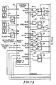
- a number of Measurement (Type) Selection signals are applied to the inputs MEAS-TYPE to select the mode that the Control Logic 10 uses to control the Counter/Timer 40.
- Table 1 shows the sixteen measurement types and the value of the MEAS-TYPE signals that selects them: TABLE 1 MEASUREMENT TYPES Meas.
- the Control Logic 10 also receives the output of the four event recognizers described above as its inputs AY, AM, BY, and EM.
- the young data from each set of event recognizers is also applied to a flip-flop 12 or 14 that delays it one CLOCK cycle, so that it is old data at the inputs AO and BO of the Control Logic 10.
- Two other inputs to the Control Logic 10 are P-1 and P-2. These indicate, respectively, that the value being programmed into the Counter/Timer 40 is one less than the terminal count or two less than the terminal count. These inputs allow the Control Logic 10 to anticipate and deal appropriately with short counts.
- the Counter/Timer 40 is implemented as an adder, so the preloaded value is the one's complement of the desired number and the terminal count occurs at all ones.
- the Control Logic 10 also has as inputs the terminal count minus two T-2, the terminal count minus one T-1, and the terminal count TC outputs from the Counter/Timer 40. These signals keep the Control Logic 10 informed of the status of the Counter/Timer as it nears the terminal count.
- Another input to the Control Logic 10 is RESET A THEN B. This signal resets that portion of the logic that is remembering that A has occurred when a RESET-FF occurs before B during an "Event A Then B" MEAS.-TYPE. (Recall from Table 1 that "Event A Then B" does not use the Counter/Timer 40.)
- the remaining input to the Control Logic is FREEZE, the TRIGGER output of the Trigger Machine 50 after it is clocked into flip-flop 54. The occurrence of this signal puts the Control Logic in a mode that allows the present measurement to be completed, but no further measurements to start.
- the Control Logic 10 outputs are STATE-IDLE, STATE-RUN, PRELOAD-IDLE, PRELOAD-RUN, PLUS1-IDLE, PLUS1-RUN, PLUS2-IDLE, PLUS2-RUN, ACTION-IDLE, and ACTION-RUN.
- Additional control logic 16-38 between the Control Logic 10 outputs and the inputs to the Counter/Timer 40 and Trigger Machine 50 qualifies these outputs with the status of the FREEZE and RESET-FF signals from the flip-flops 52 and 54 on the output of the Trigger Machine. Which of each of these pairs of signals, the IDLE version or the RUN version, is applied to the Counter/Timer 40 is determined by multiplexers 30-38 under the control of the RUN signal.
- the Control Logic block happens to be implemented with logic gates, but the same result could be achieved using RAM or PROM, or anything else that could implement the logic equations shown in Tables 2A Sthrough 2E.
- RAM or PROM any else that could implement the logic equations shown in Tables 2A Sthrough 2E.
- the nature of the Measurement Selection signals would have to be changed. For example, if RAM were used to implement these equations, appropriate programming data would be required, as well as some means, such as multiplexers, for allowing the programmed address to be asserted by different configurations of the input data in different modes, and by the controlling processor for preprogramming.
- control logic 16-38 is implemented by discrete gates and multiplexers external to the Control Logic block 10. This logic could, however, be put inside the Control Logic block 10, by the addition of suitable terms to the equations given below.
- the Counter/Timer 40 also produces a set of M signals COUNT/TIME for readback by the logic analyser's microprocessor (not shown). In one implementation, M is 52 bits wide. The microprocessor also readsback the status of the signal RUN to ascertain whether the measurement had been completed.
- the Counter/Timer 40 receives M lines of PRELOAD VALUE that is the one's complement of the desired count. It also receives a PRELOAD signal that causes the PRELOAD VALUE to be loaded.
- the COUNTER CLOCK input is connected to the system CLOCK signal.
- the PLUS 1 and PLUS 2 inputs to the Counter/Timer 40 cause the Counter/Timer to increment by one or two, respectively.
- the Counter/Timer 40 is capable of single or double counting on each occurrence of the CLOCK.
- the Counter/Timer also receives two additional inputs, LOOP ENABLE and EXT TC ENABLE. The operation of the Counter/Timer 40 and the significance of these inputs will be discussed further below in connection with Figures 2A and 2B.
- the Trigger Machine 50 receives the signal ACTION from the Control Logic 10 and produces a RESET signal or a TRIGGER signal according to its internal logic. If its inputs would cause it to try to produce both a RESET and a TRIGGER signal, the TRIGGER takes precedence.
- the TRIGGER output of the Trigger Machine 50 becomes FREEZE after it is clocked into flip-flop 54.
- the signal FREEZE is connected to the TRIGGERED input of the State Machine 50 to keep TRIGGER and FREEZE asserted after the triggering event, in this case ACTION, goes away.
- the INITIALIZE signal puts the Trigger Machine 50 into a known starting state, clears TRIGGER, and causes a RESET signal to occur.
- RESET becomes RESET-FF on the next CLOCK and operates to PRELOAD the Counter/Timer 40 through OR gate 44 and set the state to idle by disabling AND gates 16 and 18, thereby making both inputs to Mux 30 false.
- the low out of flux 30 makes RUN go false by resetting flip-flop 42 on the next CLOCK, putting Muxes 30-38 in their idle state.
- the Counter/Timer is divided into two basic portions, a fast Prescaler section 104-126 implemented in ECL and a slow Extension Counter/Timer 60 and 62 implemented in CMOS, plus assorted logic 64-102 and 128-140 implemented in the fast ECL portion of the circuitry.
- This two-speed approach saves money and power consumption, by not using the more expensive and power consuming ECL where its speed is not necessary.
- the PRELOAD signal controls the state of Muxes 104-110, selecting for their outputs the respective PRELOAD VALUE bits (PV.X) or the outputs of flip-flops 120-126, which contain the present status of the respective counter/timer value bits (CT.X).
- the outputs of these Muxes 104-110 are inputs to Bit Adders 112-118, which have as their other inputs carry signals CY from the next least significant bits, except in the case of the least significant bit which has PLUS 1 as its other input.
- the second least significant bit Mux 116 has as a third input the PLUS 2 signal.
- the CY output of the most significant bit in the Prescaler becomes the CARRY signal that goes to Fig. 2B.
- the SUM outputs of the Bit Adders 112-118 are applied to the D inputs of the flip-flops 120-126, respectively.
- These flip-flops 120-126 are clocked by CLOCK and serve to hold the results of the last operation while the asynchronous circuitry around them is resolving what the next result is to be.
- OR gate 136 produces an active output wherever the signal ROLLOVER occurs or whenever the output of AND gate 128 is active, which happens whenever the outputs CT.1-4 all four flip-flops 120-126 are set and LOOP * EXT TC is true.
- OR gate 140 also acts similarly, except that it monitors for both a terminal count minus one condition through AND gate 134 and a terminal count minus two condition through AND gate 132.
- the CARRY signal from the most significant bit of the Prescaler passes through OR gate 66 and is clocked into flip-flop 68.
- flip-flop 68 goes set, its positive going transition is felt through OR gate 72 and AND gate 74 as a clock input to the Extension Counter/Timer 60, which then counts.
- AND gate 74 is enabled by an inverted low output of flip-flop 76, which is normally reset, since STRETCHED PRELOAD is not usually active.
- the Prescaler 104-126 CARRY output can, however, occur during the same CLOCK cycle as PRELOAD command, when STRETCHED PRELOAD is still active. This can occur when the Prescaler 104-126 is preloaded with the value of 14 or 15 and the instructions from the Control Logic 10 (Fig. 1) cause a count of PLUS 2 or PLUS 1, respectively, to bring the total count to 16 during the same CLOCK cycle.
- the PRELOAD signal is stretched for an extra CLOCK cycle to become STRETCHED PRELOAD by the operation of flip-flop 80 and OR gate 78.
- the clock input to the Extension Counter/Timer arising from the occurrence of a CARRY signal must be delayed until the end of the STRETCHED PRELOAD signal. This is accomplished by flip-flop 76 and the lower input to AND gate 74. The output of flip-flop 76 does not go low and enable AND gate 74 until one clock cycle after STRETCHED PRELOAD goes false. While AND gate 74 is disabled, its low output is enabling AND gate 64 and preventing any clocking of the Extension Counter/Timer 60.
- the overall Counter/Timer 40 (Fig. 1) is set up in three basic ways selected by the status of the LOOP ENABLE and EXT TC ENABLE signals controlled by the microprocessor (not shown). For counts of fifteen or less, both LOOP ENABLE and EXT TC ENABLE are low. For counts of 16 to 31, LOOP ENABLE is made high and EXT TC ENABLE is made low. For counts of 32 or greater, both LOOP ENABLE and EXT TC ENABLE are made high.
- Figs. 2A and 2B let us first analyze the operation of the Counter/Timer 40 (Fig. 1) for a count of fifteen or less, say "3".
- the PRELOAD VALUE for the four least significant bits is "12" (the one's complement of 3), or PV.4 equals 1, PV.3 equals 1, PV.2 equals 0, and PV.1 equals 0.
- the higher order 48 bits for the Extension Counter/Timer 60 are loaded with all ones.
- LOOP ENABLE and EXT TC ENABLE are both low. However, LOOP ENABLE and EXT TC ENABLE are both inverted at the inputs to OR gates 90 and 94, respectively.
- OR gates 90 and 94 have high outputs and AND gate 92 is satisfied from the outset, so that the signal LOOP * EXT TC is immediately true.
- the high on LOOP * EXT TC not only enables AND gates 128, 130, 132, and 134, but it also enables one side of AND gate 96, so that the next CARRY will satisfy it. If another count instruction is received and the Prescaler rolls over, CARRY is produced and AND gate 96 is satisfied.
- ROLLOVER also perpetuates itself through AND gate 98 and OR gate 100, until the PRELOAD signal goes true and its inverted version disables AND gate 98 and flip-flop 102 resets (assuming that another CARRY does not occur at the same time).
- the occurrence of PRELOAD also disables AND gate 84 and thereby resets the PRESCALER LOOPED flip-flop 88 (assuming that another CARRY does not occur at the same time).
- the next sixteen counts cause the Prescaler 104-126 to count back up to a full count again, for a total of 19.
- ROLLOVER also perpetuates itself through AND gate 98 and OR gate 100, until the PRELOAD signal goes true and its inverted version disables AND gate 98 and flip-flop 102 resets.
- the occurrence of PRELOAD also disables AND gate 84 and thereby resets the PRESCALER LOOPED flip-flop 88.
- ROLLOVER also perpetuates itself through AND gate 98 and OR gate 100, until the PRELOAD signal goes true and its inverted version disables AND gate 98 and flip-flop 102 resets.
- the occurrence of PRELOAD also disables AND gate 84 and thereby resets the PRESCALER LOOPED flip-flop 88.
- Fig. 3 is a timing diagram showing how the Control Logic 10, the auxiliary control logic 16-38, and Counter/Timer 40 operate together to perform a "duration greater than or equal to" measurement.
- CLOCK cycles are shown on the first line, numbered in their high-going half cycles for reference.
- the second line of this timing diagram, "ACTUAL EVENT A” is the data that was sampled at the data acquisition probe. It can be changing asynchronously with the system CLOCK, so all we really know about it is its status at the time of the system CLOCK edges, shown for the first cycle as the points within the circles.
- the rising edge of the 200 MHz system CLOCK is used throughout most of the logic analyzer to form a synchronous system. However, at the acquisition probe of the logic analyser a second set of data acquisition flip-flips acquire their data using the falling edge of this clock, thus doubling the data sampling rate to an effective rate of 400 MHz.
- the data clocked using the rising edge of the system CLOCK is labeled "middle” data.
- the data clocked using the falling edge is labeled "young”. Both the "young" and the "middle” data are clocked into the system together on the next rising CLOCK edge.
- E.R.A-MID and E.R.A-MID are derived from ACTUAL EVENT A and describe its status during the previous CLOCK cycle.
- E.R.A-OLD tracks the value of E.R.A-YNG one CLOCK cycle later, thus reflecting the value for the half cycle previous to the current middle value.
- Equation Value contains a summary of the status of the lines E.R.A-YNG, E.R.A-MID, and E.R.A-OLD for Event Recogniser A, but in the order OLD-MID-YNG. That is, a value such as "A011” means that, for Event Recognizer A's data, OLD is low, while MID and YNG are high. An example of "A011” can be seen under CLOCK cycle 4.
- the line in the timing diagram STATE-flux describes the output of multiplexer 30.
- Multiplexer 30 is under the control of the signal RUN which also controls the other multiplexers 32, 34, 36, and 38.
- RUN controls whether STATE-flux is the STATE-IDLE signal as qualified by AND gate 16 or the STATE-RUN signal as qualified by AND gate 18. If either FREEZE or RESET-FF are high, AND gate 16 is disabled. If RESET-FF is high, AND gate 18 is disabled.
- the line in the timing diagram PRELOAD-flux describes the output of multiplexer 32 which similarly, under the control of the signal RUN, selects between the signal PRELOAD-IDLE as gated by AND 20 and the signal PRELOAD-RUN. Note that the state of the signal PRELOAD-flux can be rendered irrelevant by the operation of RESET-FF through OR gate 44.
- Multiplexers 34, 36, and 38 operate similarly to select between the IDLE and RUN versions of PLUS 1, PLUS 2, and ACTION to produce the next three signals shown in the timing diagram, PLUS1-MUX, PLUS2-MUX, and ACTION-MUX.
- the inputs to multiplexer 38 are not qualified by the state of FREEZE and RESET-FF as the other two are. This is because FREEZE's affects on ACTION are explicitly stated in the equations of the Control Logic block, to allow greater versatility in their implementation.
- RESET-FF is not included, as its effect is part of the function of the Trigger Machine block 50.
- the Counter/Timer 40 is implemented as an adder that counts up to a terminal count of all "1"s.
- RESET-FF and FREEZE are the asynchronous signals RESET and TRIGGER synchronized by CLOCK in the flip-flops 52 and 54, respectively.
- FREEZE is used at AND gates 16, 20, 22 and 26 to block the IDLE inputs to the Muxes 30, 32, 34, and 36.
- the FREEZE command puts the Counter/Timer 40 and the Control Logic 10 in a condition that permits the present measurement to be completed, but no further measurements to be started, once a trigger has occurred.
- RESET is asserted and then dis-asserted. These changes are clocked through flip-flop 52 so that RESET-FF initializes the additional logic circuitry 16-38 and the Counter/Timer 40. RESET-FF causes a PRELOAD input to the Counter/Timer 40 through OR gate 44.
- RESET-FF goes low indicating the beginning of a measurement.
- the COUNTER value is TC-3, i.e., terminal count minus three.
- ACTUAL EVENT A remains high for all of this cycle, so E.R.A-YNG and E.R.A-MID are both high, as is E.R.A-OLD.
- the Equation Value is "A111".
- Equation Value is "A011", reflecting the status of the signals E.R.A-OLD, E.R.A-MID, and E.R.A-YNG.
- the XXXX-IDLE signals are the ones seen on all five of the XXXX-MUX signals.
- PRELOAD-MUX passes through OR gate 44 and on into the PRELOAD input of the Counter/Timer 40 during this same cycle, thus causing the COUNTER value to go back to TC-3 some time before the end of this cycle.
- Equation Value "A011" also produces a change to high on the PLUS2-MUX line during this cycle (Table 2D, line 0). Because ACTUAL EVENT A was high for both halves of this cycle (cycle 4), the counter is incremented twice, once for each 2.5 ns interval. The equations in line 0 of the other two Tables, 2C and 2E, are not satisfied by this Equation Value, so PLUS1-MUX and ACTION-MUX remain low through the end of this cycle. During the next cycle (cycle 5), the Counter/Timer 40 output reacts to the PLUS2 input and ends up holding a COUNTER value of TC-1.
- Equation Value is "A111" reflecting the fact that ACTUAL EVENT A remained high throughout cycle 4. Because the STATE-MUX signal was high by the end of the preceding cycle, RUN has now gone high and we look at the run portions of the tables containing the Control Logic 10 equations. Looking at line 8 of Table 2A, neither ORed term within the parentheses is satisfied, so the value of all of the terms within the parentheses is a zero, which, inverted by the "n" in front of the parentheses, makes the STATE-RUN output a one. Thus, STATE-MUX remains high during this cycle, and RUN will be high during the next cycle (cycle 6).
- Equation Value (during cycle 6) "A111" does not satisfy either of terms in line 8 of Table 2C, but does satisfy the only term in line 8 of Table 2D, generating another cycle of high signal on PLUS2-RUN and PLUS2-MUX and causing the Counter/Timer 40 to double increment again. This is the desired result, since ACTUAL EVENT A was high during both halves of the last cycle. As a result of this third cycle of PLUS2-MUX high, the COUNTER value goes to TC+3 during the next cycle (cycle 7). And, as during the last cycle, the Equation Value of "A111", in conjunction with the high levels now remaining on T-1 and T-2, satisfies both of the last two terms of the equation on line 16 of Table 2E. Accordingly, ACTION-MUX remains high during this cycle.
- Equation Value in cycle 7 is "A110".
- the desired behavior of the Counter/Timer 40 is to count by one, and that is what happens.
- "A110” satisfies the first term within the parentheses on line 8 of Table 2A, "AXX0”, and the "n” inversion makes STATE-RUN and STATE-MUX go to low during this cycle.
- PRELOAD-RUN is still disabled by the FREEZE term in line 8 of Table 2B.
- "A110” also satisfies the first term of the equation on line 8 of Table 2C to generate a high PLUS1-RUN and PLUS1-MUX.
- Fig. 4 shows an alternative circuit arrangement that permits higher system CLOCK rates.
- the Control Logic 10 of Fig. 1 is divided into two parts in Fig. 4, Control Logic 10a and Action Logic 10b. Additional flip-flops 110-116 and 118-124 permit the Counter/Timer 40, Action Logic 10b, and the Trigger Machine 50 to run one CLOCK cycle behind the Control Logic 10a. This permits a higher speed of operation, but with the consequence that the occurrence of FREEZE is delayed one CLOCK cycle in getting back to the Control Logic 10a and additional logic gates 16-28.
- AND gates 126 and 128 act to block the ACTION-MUX signal from reaching the Trigger Machine if a RESET-FF occurs during the last CLOCK cycle of a measurement that uses the scounter/Timer 40.
- RUN At the end of an acquisition, if a measurement is still in progress RUN is high. The status of RUN is readback by the microprocessor along with the COUNT/TIME measurement value. This permits the user to be given the measurement value, but to also be informed that the measurement was never completed.
- the microprocessor After the microprocessor (not shown) reads back the final value held by the counter/timer, it must add to it the one's complement of the PRELOAD VALUE with which the Counter/Timer 40 was preloaded. This produces the total measured interval of interest for display to the user.
Landscapes
- Engineering & Computer Science (AREA)
- General Engineering & Computer Science (AREA)
- Physics & Mathematics (AREA)
- General Physics & Mathematics (AREA)
- Theoretical Computer Science (AREA)
- Computer Hardware Design (AREA)
- Quality & Reliability (AREA)
- Measurement Of Unknown Time Intervals (AREA)
- Debugging And Monitoring (AREA)
- Test And Diagnosis Of Digital Computers (AREA)
Applications Claiming Priority (2)
| Application Number | Priority Date | Filing Date | Title |
|---|---|---|---|
| US42879589A | 1989-10-30 | 1989-10-30 | |
| US428795 | 2003-05-02 |
Publications (2)
| Publication Number | Publication Date |
|---|---|
| EP0426281A2 true EP0426281A2 (de) | 1991-05-08 |
| EP0426281A3 EP0426281A3 (en) | 1992-02-05 |
Family
ID=23700431
Family Applications (1)
| Application Number | Title | Priority Date | Filing Date |
|---|---|---|---|
| EP19900309247 Withdrawn EP0426281A3 (en) | 1989-10-30 | 1990-08-23 | Enhanced counter/timer behavior in a logic analyzer |
Country Status (2)
| Country | Link |
|---|---|
| EP (1) | EP0426281A3 (de) |
| JP (1) | JPH03170070A (de) |
Family Cites Families (1)
| Publication number | Priority date | Publication date | Assignee | Title |
|---|---|---|---|---|
| JPS60213873A (ja) * | 1984-04-06 | 1985-10-26 | Advantest Corp | ロジツクアナライザ |
-
1990
- 1990-08-23 EP EP19900309247 patent/EP0426281A3/en not_active Withdrawn
- 1990-10-30 JP JP2293489A patent/JPH03170070A/ja active Pending
Also Published As
| Publication number | Publication date |
|---|---|
| JPH03170070A (ja) | 1991-07-23 |
| EP0426281A3 (en) | 1992-02-05 |
Similar Documents
| Publication | Publication Date | Title |
|---|---|---|
| US4979177A (en) | Enhanced counter/timer resolution in a logic analyzer | |
| US4654848A (en) | Multi-trigger logic analyzer | |
| US5854996A (en) | Logic signal extraction | |
| EP0257911A2 (de) | Speicherzeiger mit Gruppierung | |
| US7366049B2 (en) | Apparatus and method for updating data in a dual port memory | |
| US6671876B1 (en) | Monitoring of software operation for improving computer program performance | |
| US5347540A (en) | Dynamic storage allocation in a logic analyzer | |
| JP2554460B2 (ja) | 論理動作観測装置 | |
| US4128892A (en) | Pulse width measurement circuitry | |
| US4752928A (en) | Transaction analyzer | |
| US4726045A (en) | Low jitter digital delay generator | |
| EP0260502A2 (de) | Zeitstempelschaltung mit automatischer Bereichregelung | |
| US5359533A (en) | Method for determining a frequency/time profile of hits, and device for carrying out the method | |
| US5325341A (en) | Digital timer apparatus and method | |
| EP0426281A2 (de) | Verbesserte Zähler-/Zeitgeberverhältnisse in einem Logikanalysator | |
| WO2004099987A1 (en) | Logic analyzer data retrieving circuit and its retrieving method | |
| US7089437B2 (en) | Apparatus for determining power consumed by a bus of a digital signal processor using counted number of logic state transitions on bus | |
| US6895070B2 (en) | Counter circuit | |
| US5185770A (en) | Variable frequency dividing circuits | |
| US5301335A (en) | Register with selective wait feature | |
| US6330579B1 (en) | Fir filter based upon squaring | |
| KR940009815B1 (ko) | 마이컴의 직렬포트를 이용한 주파수 측정장치 및 방법 | |
| JP2718402B2 (ja) | インサーキット・エミュレータ内蔵用の時間測定回路 | |
| JPS63186153A (ja) | ロジツクアナライザ | |
| JPS60214266A (ja) | 信号記憶装置 |
Legal Events
| Date | Code | Title | Description |
|---|---|---|---|
| PUAI | Public reference made under article 153(3) epc to a published international application that has entered the european phase |
Free format text: ORIGINAL CODE: 0009012 |
|
| AK | Designated contracting states |
Kind code of ref document: A2 Designated state(s): DE FR GB NL |
|
| PUAL | Search report despatched |
Free format text: ORIGINAL CODE: 0009013 |
|
| AK | Designated contracting states |
Kind code of ref document: A3 Designated state(s): DE FR GB NL |
|
| 17P | Request for examination filed |
Effective date: 19920627 |
|
| 17Q | First examination report despatched |
Effective date: 19941011 |
|
| STAA | Information on the status of an ep patent application or granted ep patent |
Free format text: STATUS: THE APPLICATION IS DEEMED TO BE WITHDRAWN |
|
| 18D | Application deemed to be withdrawn |
Effective date: 19950222 |