EP0426302A1 - Maschine mit veränderlicher Verbrennungskammer - Google Patents
Maschine mit veränderlicher Verbrennungskammer Download PDFInfo
- Publication number
- EP0426302A1 EP0426302A1 EP90310728A EP90310728A EP0426302A1 EP 0426302 A1 EP0426302 A1 EP 0426302A1 EP 90310728 A EP90310728 A EP 90310728A EP 90310728 A EP90310728 A EP 90310728A EP 0426302 A1 EP0426302 A1 EP 0426302A1
- Authority
- EP
- European Patent Office
- Prior art keywords
- engine
- fuel
- valve
- combustion chamber
- cylinder
- Prior art date
- Legal status (The legal status is an assumption and is not a legal conclusion. Google has not performed a legal analysis and makes no representation as to the accuracy of the status listed.)
- Granted
Links
- 238000002485 combustion reaction Methods 0.000 title claims abstract description 47
- 239000000446 fuel Substances 0.000 claims abstract description 68
- 238000004891 communication Methods 0.000 claims abstract description 16
- 230000006854 communication Effects 0.000 claims abstract description 16
- 238000002347 injection Methods 0.000 claims description 13
- 239000007924 injection Substances 0.000 claims description 13
- 229910010293 ceramic material Inorganic materials 0.000 claims description 8
- 241001052209 Cylinder Species 0.000 claims description 2
- LFQSCWFLJHTTHZ-UHFFFAOYSA-N Ethanol Chemical compound CCO LFQSCWFLJHTTHZ-UHFFFAOYSA-N 0.000 description 18
- 235000019441 ethanol Nutrition 0.000 description 18
- 239000003570 air Substances 0.000 description 10
- 230000006835 compression Effects 0.000 description 8
- 238000007906 compression Methods 0.000 description 8
- 239000007789 gas Substances 0.000 description 6
- 239000003921 oil Substances 0.000 description 4
- 239000011810 insulating material Substances 0.000 description 3
- 238000009834 vaporization Methods 0.000 description 3
- 230000008016 vaporization Effects 0.000 description 3
- MCMNRKCIXSYSNV-UHFFFAOYSA-N Zirconium dioxide Chemical compound O=[Zr]=O MCMNRKCIXSYSNV-UHFFFAOYSA-N 0.000 description 2
- 238000004364 calculation method Methods 0.000 description 2
- 239000002803 fossil fuel Substances 0.000 description 2
- 239000000463 material Substances 0.000 description 2
- 239000000126 substance Substances 0.000 description 2
- 206010037660 Pyrexia Diseases 0.000 description 1
- 208000036366 Sensation of pressure Diseases 0.000 description 1
- 229910052581 Si3N4 Inorganic materials 0.000 description 1
- 238000003915 air pollution Methods 0.000 description 1
- 239000012080 ambient air Substances 0.000 description 1
- 230000008901 benefit Effects 0.000 description 1
- 238000001816 cooling Methods 0.000 description 1
- 229960004756 ethanol Drugs 0.000 description 1
- 238000012986 modification Methods 0.000 description 1
- 230000004048 modification Effects 0.000 description 1
- 235000019645 odor Nutrition 0.000 description 1
- 230000002265 prevention Effects 0.000 description 1
- 230000004044 response Effects 0.000 description 1
- HQVNEWCFYHHQES-UHFFFAOYSA-N silicon nitride Chemical compound N12[Si]34N5[Si]62N3[Si]51N64 HQVNEWCFYHHQES-UHFFFAOYSA-N 0.000 description 1
Images
Classifications
-
- F—MECHANICAL ENGINEERING; LIGHTING; HEATING; WEAPONS; BLASTING
- F02—COMBUSTION ENGINES; HOT-GAS OR COMBUSTION-PRODUCT ENGINE PLANTS
- F02D—CONTROLLING COMBUSTION ENGINES
- F02D15/00—Varying compression ratio
- F02D15/04—Varying compression ratio by alteration of volume of compression space without changing piston stroke
-
- F—MECHANICAL ENGINEERING; LIGHTING; HEATING; WEAPONS; BLASTING
- F02—COMBUSTION ENGINES; HOT-GAS OR COMBUSTION-PRODUCT ENGINE PLANTS
- F02B—INTERNAL-COMBUSTION PISTON ENGINES; COMBUSTION ENGINES IN GENERAL
- F02B19/00—Engines characterised by precombustion chambers
-
- F—MECHANICAL ENGINEERING; LIGHTING; HEATING; WEAPONS; BLASTING
- F02—COMBUSTION ENGINES; HOT-GAS OR COMBUSTION-PRODUCT ENGINE PLANTS
- F02B—INTERNAL-COMBUSTION PISTON ENGINES; COMBUSTION ENGINES IN GENERAL
- F02B19/00—Engines characterised by precombustion chambers
- F02B19/02—Engines characterised by precombustion chambers the chamber being periodically isolated from its cylinder
-
- F—MECHANICAL ENGINEERING; LIGHTING; HEATING; WEAPONS; BLASTING
- F02—COMBUSTION ENGINES; HOT-GAS OR COMBUSTION-PRODUCT ENGINE PLANTS
- F02B—INTERNAL-COMBUSTION PISTON ENGINES; COMBUSTION ENGINES IN GENERAL
- F02B2275/00—Other engines, components or details, not provided for in other groups of this subclass
- F02B2275/14—Direct injection into combustion chamber
-
- F—MECHANICAL ENGINEERING; LIGHTING; HEATING; WEAPONS; BLASTING
- F02—COMBUSTION ENGINES; HOT-GAS OR COMBUSTION-PRODUCT ENGINE PLANTS
- F02F—CYLINDERS, PISTONS OR CASINGS, FOR COMBUSTION ENGINES; ARRANGEMENTS OF SEALINGS IN COMBUSTION ENGINES
- F02F1/00—Cylinders; Cylinder heads
- F02F1/24—Cylinder heads
- F02F2001/244—Arrangement of valve stems in cylinder heads
- F02F2001/247—Arrangement of valve stems in cylinder heads the valve stems being orientated in parallel with the cylinder axis
-
- Y—GENERAL TAGGING OF NEW TECHNOLOGICAL DEVELOPMENTS; GENERAL TAGGING OF CROSS-SECTIONAL TECHNOLOGIES SPANNING OVER SEVERAL SECTIONS OF THE IPC; TECHNICAL SUBJECTS COVERED BY FORMER USPC CROSS-REFERENCE ART COLLECTIONS [XRACs] AND DIGESTS
- Y02—TECHNOLOGIES OR APPLICATIONS FOR MITIGATION OR ADAPTATION AGAINST CLIMATE CHANGE
- Y02T—CLIMATE CHANGE MITIGATION TECHNOLOGIES RELATED TO TRANSPORTATION
- Y02T10/00—Road transport of goods or passengers
- Y02T10/10—Internal combustion engine [ICE] based vehicles
- Y02T10/12—Improving ICE efficiencies
Definitions
- the present invention relates to an engine with a variable combustion chamber which can be modified into a direct-injection-type combustion chamber when the engine operates under low load and a prechamber-type combustion chamber when the engine operates under high load, and more particularly to such an engine which employs alcohol as fuel.
- Fuel for use in conventional engines is fossil fuel such as gasoline, light oil, or the like.
- the fossil fuel is a limited natural resource.
- Exhaust gases emitted from engines which burn gasoline, light oil, etc. contain harmful substances which are partly responsible for the air pollution.
- Various efforts have been made to eliminate or reduce these shortcomings.
- an engine which uses, as fuel, alcohol which is chemically or biochemically produced.
- Alcohol has a greater latent heat value of vaporization and generates smaller heat than conventional fuels. For example, in order to produce the same amount of heat, it is necessary to supply an engine with alcohol which is about 1.6 times light oil. Since the amount of alcohol injected into an engine cylinder is larger, air and injected alcohol are not easily mixed together in the combustion chamber, and the time required for the alcohol to be diffused and combusted is longer. Especially when the engine is subjected to high load, the amount of alcohol to be injected is increased and hence the engine output power and the combustion efficiency are lowered.
- Japanese Utility Model Publication No. 57(1982)-164224 discloses an engine having a main combustion chamber and an auxiliary chamber communicating therewith.
- a third valve is disposed in the opening of the auxiliary chamber.
- the opening of the auxiliary chamber is closed by the third valve, giving the engine a higher compression ratio.
- the third valve is opened on each compression stroke, thus reducing the compression ratio for the prevention of knocking.
- the disclosed engine cannot solve the problems referred to above.
- an engine comprising a cylinder, a piston slidably disposed in the cylinder, a first combustion chamber defined in the piston, a cylinder head mounted on the cylinder, a second combustion chamber defined in the cylinder head and communicating with the cylinder through a communication port, a valve mounted in the cylinder head for opening and closing the communication port, intake and exhaust passages communicating with the cylinder, a first fuel injection nozzle for injecting fuel into the first combustion chamber, a second fuel injection nozzle for injection fuel into the second combustion chamber, fuel supply means for supplying fuel to one of the first and second fuel injection nozzles at a time, valve actuating means for actuating the valve to open and close the communication port, load detecting means for detecting a load on the engine and control means for operating the valve actuating means to open the valve and controlling the fuel supply means to supply fuel to the second fuel injection nozzle when the load on the engine as detected by the load detecting means is equal to or higher than
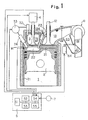
- Fig. 1 shows, partly in block form, an engine with a variable combustion chamber according to the present invention.
- the engine has a cylinder 1 whose inner wall surface is lined with a cylinder sleeve 11 that is made of a heat insulating ceramic material such as silicon nitride, zirconia, or the like.
- the cylinder sleeve 11 has in its upper portion a pressure sensor 14 for measuring the pressure in the cylinder 1.
- a cylinder head mounted on the cylinder 1 has an intake passage 13 defined therein which is selectively openable and closable by an intake valve 12.
- the cylinder head also has an exhaust passage defined therein which is selectively openable and closable by an exhaust valve.
- a piston 2 is slidably disposed in the cylinder 1.
- the piston 2 has a piston head covered with a heat insulating layer 21 which is made of the same heat insulating ceramic material as the material of the cylinder sleeve 11.
- the piston head of the piston 2 has a recess defined therein as a first combustion chamber 22.
- the cylinder head supports a glow plug 23 which can be positioned in the first combustion chamber 22 when the piston 2 reaches the top dead center and a first nozzle 24 for injecting fuel such as alcohol fuel into the first combustion chamber 22 when the the piston 2 reaches the top dead center.
- the cylinder head has a second combustion chamber 3 defined therein and communicating with the cylinder 1 through a communication port 30.
- the communication port 30 is openable and closable by a valve 31 disposed therein, the valve 31 being axially slidably supported in the cylinder head by a valve guide 34.
- the cylinder head supports a second nozzle 32 for injecting fuel such as alcohol fuel into the second combustion chamber 3.
- the first nozzle 24 and the second nozzle 32 are connected to a fuel pump 33 so that they are supplied with fuel such as alcohol fuel.
- the fuel pump 33 can start and stop the supply of fuel to the first nozzle 24 and the second nozzle 32 at timings which can be freely varied by signals applied to the fuel pump 33.
- the second combustion chamber 3 has an inner wall made of the same heat insulating ceramic material as the material of the cylinder sleeve 11.
- the valve 31 and the valve guide 34 are made of a high-strength heat insulating ceramic material.
- a valve opening and closing mechanism 4 is coupled to the shank end of the valve 31.
- the valve opening and closing mechanism 4 comprises an electromagnetic solenoid which electromagnetically attracts a magnetic member joined to the shank end of the valve 31.
- the valve 31 is normally lifted upwardly in Fig. 1, closing the communication port 30.
- the valve 31 is driven downwardly by the valve opening and closing mechanism 4, the valve 31 opens the communication port 30.
- the pressure sensor 14 the glow plug 23 the fuel pump 33, and the valve opening and closing mechanism 4 are electrically connected to an input/output interface 54 of a control unit 5.
- the control unit 5 comprises, in addition to the input/output interface 54, a ROM 52 for storing a program and relevant data, a CPU 51 for carrying out calculations under the control of the program stored in the ROM 52, a RAM 53 for temporarily storing the results of the calculations and data, and a control memory 55 for controlling the flow of signals in the control unit 5.
- the intake passage 13 is connected to the outlet port of a compressor of a turbocharger 6.
- the compressor of the turbocharger 6 has an inlet port connected to an intake pipe 61 which is branched into a bypass pipe 63 coupled to the intake passage 13.
- a selector valve 62 is disposed in the intake pipe 61 where the bypass pipe 63 is branched therefrom.
- the selector valve 62 is connected to a solenoid actuator 64 which selectively opens and closes the selector valve 62.
- the solenoid actuator 64 is electrically connected to the input/output interface 54 of the control unit 5, and opens and closes the selector valve 62 in response to a signal from the input/output interface 54.
- the turbocharger 6 has a rotatable shaft (not shown) on which a rotary electric machine (not shown) is mounted.
- a rotary electric machine (not shown) is mounted.
- the load on the engine is detected by a load sensor 7 based on the amount of depression of an accelerator pedal (not shown).
- a load signal detected by the load sensor 7 is applied to the input/output interface 54.
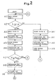
- step S1 an engine load signal L from the load sensor 7 is read into the control unit 5 through the input/output interface 54.
- the engine load signal L is then compared with a preset load Le stored in the ROM 52 in a step S2. If L ⁇ Le, then control goes to a step S3, and if L ⁇ Le, then control goes to a step S10.
- a signal is transmitted from the control unit 5 to the valve opening and closing mechanism 4 to move the valve 31 downwardly, thus opening the communication port 30.
- a signal is sent from the control unit 5 to the fuel pump 33 to control the fuel pump 33 to supply fuel to the second nozzle 32 at a predetermined timing in a step S4.
- a signal is also sent from the control unit 5 to the solenoid actuator 64 to cause the selector valve 62 to close the bypass pipe 63 in a step S5.
- Intake air is now introduced into the intake pipe 61 and compressed by the compressor of the turbocharger 6, so that compressed intake air is supplied into the cylinder 1 through the intake passage 13.
- a signal is transmitted from the control unit 5 to the fuel pump 33 to stop the supply of fuel to the first nozzle 24.
- the steps S3 through S6 operate the engine as a prechamber-type engine.
- control goes from the step S6 to a step S7 to monitor the pressure in the cylinder 1.
- step S7 a cylinder pressure signal P from the pressure sensor 14 is read into the control unit 5, and compared with a maximum cylinder pressure Pmax stored in the ROM 52. If P ⁇ Pmax then control proceeds to steps S8, S9. If P ⁇ Pmax, then control returns to the step S1 to execute the entire flow cycle again.
- step S8 a signal is applied from the control unit 5 to the fuel pump 33 to stop the supply of fuel to the second nozzle 32.
- step S9 fuel is supplied to the first nozzle 24 for lower engine load, thereby to lower the pressure in the cylinder 1.
- step S2 If L ⁇ Le in the step S2, since the engine is under low load, control goes to steps S10 through S13 for operating the engine as a direct-injection-type engine with only the first combustion chamber 22 used as a sole combustion chamber.
- a signal is sent from the control unit 5 to the valve opening and closing mechanism 4 to lift the valve 31 thereby closing the communication port 30 in the step S10.
- step S11 a signal is applied from the control unit 5 to the fuel pump 33 to stop the supply of fuel to the second nozzle 32.
- step S12 fuel starts being supplied to the first nozzle 24.
- step S13 a signal is sent from the control unit 5 to the solenoid actuator 64 to move the selector valve 62 to open the bypass pipe 63. Thereafter, control goes back to the step 1 for the execution of the entire flow cycle again.
- the direct-injection-type engine which is operated by the steps S10 through S13 has a compression ratio ranging from 20 to 21 which is higher than the compression ratio of ordinary direct-injection-type engines. Since the temperature in the cylinder at the compression stroke end is higher than the corresponding temperature, about 650°C, of ordinary direct-injection-type engines, the direct-injection-type engine according to the present invention can be well started even if alcohol fuel is used. Since the direct-injection-type engine has a smaller combustion chamber inner wall area, it has a lower cooling loss and hence provides good fuel economy.
- the engine of the present invention operates as a direct-injection-type engine or a prechamber-type engine
- the inner wall of the combustion chamber is covered with a heat insulating material
- exhaust gases emitted from the engine are of high temperature and hence have large energy.
- the surface of the heat insulating material on the inner wall of the cylinder is prevented from being abnormally heated to high temperature since injected fuel is rapidly vaporized while absorbing latent heat of vaporization from the surface of the heat insulating material.
- the engine when the engine is under low load with the amount of injected fuel being low, the engine operates as a direct-injection-type engine having a high compression ratio. Therefore, the fuel consumption is low, the engine can be well started, and emission of unburned gases is minimized.
- the engine When the engine is under high load, it operates as a prechamber-type engine. Therefore, alcohol fuel and intake air are rapidly mixed together, and the output power and efficiency of the engine are not lowered.
Landscapes
- Engineering & Computer Science (AREA)
- Chemical & Material Sciences (AREA)
- Combustion & Propulsion (AREA)
- Mechanical Engineering (AREA)
- General Engineering & Computer Science (AREA)
- Combustion Methods Of Internal-Combustion Engines (AREA)
- Output Control And Ontrol Of Special Type Engine (AREA)
Applications Claiming Priority (2)
| Application Number | Priority Date | Filing Date | Title |
|---|---|---|---|
| JP1256418A JPH0692750B2 (ja) | 1989-09-30 | 1989-09-30 | 燃焼室可変エンジン |
| JP256418/89 | 1989-09-30 |
Publications (2)
| Publication Number | Publication Date |
|---|---|
| EP0426302A1 true EP0426302A1 (de) | 1991-05-08 |
| EP0426302B1 EP0426302B1 (de) | 1994-04-20 |
Family
ID=17292394
Family Applications (1)
| Application Number | Title | Priority Date | Filing Date |
|---|---|---|---|
| EP90310728A Expired - Lifetime EP0426302B1 (de) | 1989-09-30 | 1990-10-01 | Maschine mit veränderlicher Verbrennungskammer |
Country Status (4)
| Country | Link |
|---|---|
| US (1) | US5069178A (de) |
| EP (1) | EP0426302B1 (de) |
| JP (1) | JPH0692750B2 (de) |
| DE (1) | DE69008307T2 (de) |
Cited By (1)
| Publication number | Priority date | Publication date | Assignee | Title |
|---|---|---|---|---|
| WO2004046518A1 (en) * | 2002-11-20 | 2004-06-03 | Zdzislaw Pawlak | Internal combustion engine with accumulation chamber |
Families Citing this family (11)
| Publication number | Priority date | Publication date | Assignee | Title |
|---|---|---|---|---|
| US5156123A (en) * | 1989-09-30 | 1992-10-20 | Isuzu Motors Limited | Engine with variable combustion chamber |
| JP3047493B2 (ja) * | 1991-03-14 | 2000-05-29 | いすゞ自動車株式会社 | 断熱副室式エンジン |
| US5201907A (en) * | 1991-06-28 | 1993-04-13 | Mazda Motor Corporation | Internal combustion engine |
| US5222993A (en) * | 1992-09-28 | 1993-06-29 | Gas Research Institute | Ignition system for water-cooled gas engines |
| JP3048476B2 (ja) * | 1992-09-29 | 2000-06-05 | 株式会社いすゞセラミックス研究所 | リフト量可変制御弁を備えた副室式ガスエンジン |
| DE19624964A1 (de) * | 1996-06-22 | 1998-01-02 | Motoren Werke Mannheim Ag | Zündsystem für einen Gasmotor |
| US20060219210A1 (en) * | 2005-03-30 | 2006-10-05 | Brett Bailey | Internal combustion engine with variable volume prechamber |
| KR101467111B1 (ko) * | 2013-08-28 | 2014-11-28 | 현대중공업 주식회사 | 엔진 |
| US9759155B2 (en) * | 2014-06-18 | 2017-09-12 | Joseph Facciano | Enhanced performance poppet valves for internal combustion engines |
| JP7186044B2 (ja) | 2018-09-26 | 2022-12-08 | 株式会社Soken | 内燃機関用のスパークプラグ |
| US11408329B2 (en) * | 2019-12-19 | 2022-08-09 | Board Of Trustees Of Michigan State University | Engine turbulent jet ignition system |
Citations (3)
| Publication number | Priority date | Publication date | Assignee | Title |
|---|---|---|---|---|
| FR899431A (fr) * | 1942-11-14 | 1945-05-30 | Moteur diesel à précompression de l'air de combustion pour l'augmentation de la puissance | |
| US4401072A (en) * | 1979-03-12 | 1983-08-30 | Toyota Jidosha Kabushiki Kaisha | Combustion chamber of a compression-ignition type internal combustion engine |
| FR2542812A1 (fr) * | 1983-03-18 | 1984-09-21 | Volkswagenwerk Ag | Dispositif de commande du taux de compression d'un moteur a combustion interne |
Family Cites Families (10)
| Publication number | Priority date | Publication date | Assignee | Title |
|---|---|---|---|---|
| US4160432A (en) * | 1973-12-22 | 1979-07-10 | Nissan Motor Company, Limited | Internal combustion engine having main and auxiliary combustion chambers |
| US4161927A (en) * | 1978-03-27 | 1979-07-24 | Honda Giken Kogyo Kabushiki Kaisha | Fuel injection for divided auxiliary chamber of engine |
| US4241703A (en) * | 1978-11-22 | 1980-12-30 | Lin Liaw Jiing | Devices for promoting compression ratio of fuel mixture in engines |
| US4372264A (en) * | 1979-12-26 | 1983-02-08 | Trucco Horacio A | Internal combustion engine for diverse fuels |
| DE3207179A1 (de) * | 1982-02-27 | 1983-09-08 | Robert Bosch Gmbh, 7000 Stuttgart | Hubkolbenbrennkraftmaschine |
| FR2534970A1 (fr) * | 1982-10-22 | 1984-04-27 | Chenesseau | Moteur a combustion interne utilisable avec un carburant a haute chaleur de vaporisation |
| US4532899A (en) * | 1983-06-23 | 1985-08-06 | Anthony Lorts | Internal combustion engine fuel-injection system |
| IT8548542A0 (it) * | 1985-09-10 | 1985-09-10 | Cola Umberto | Dispositivo per aumentare la potenza, la velocita' e il rendimento del motore a scoppio e del motore diesel |
| US4726331A (en) * | 1986-05-06 | 1988-02-23 | Yamaha Hatsudoki Kabushiki Kaisha | Means for variable valve timing for engine |
| AU609442B2 (en) * | 1987-01-21 | 1991-05-02 | Kabushiki Kaisha Hareyama Giken | Internal combustion engine |
-
1989
- 1989-09-30 JP JP1256418A patent/JPH0692750B2/ja not_active Expired - Lifetime
-
1990
- 1990-09-28 US US07/589,545 patent/US5069178A/en not_active Expired - Fee Related
- 1990-10-01 DE DE69008307T patent/DE69008307T2/de not_active Expired - Fee Related
- 1990-10-01 EP EP90310728A patent/EP0426302B1/de not_active Expired - Lifetime
Patent Citations (3)
| Publication number | Priority date | Publication date | Assignee | Title |
|---|---|---|---|---|
| FR899431A (fr) * | 1942-11-14 | 1945-05-30 | Moteur diesel à précompression de l'air de combustion pour l'augmentation de la puissance | |
| US4401072A (en) * | 1979-03-12 | 1983-08-30 | Toyota Jidosha Kabushiki Kaisha | Combustion chamber of a compression-ignition type internal combustion engine |
| FR2542812A1 (fr) * | 1983-03-18 | 1984-09-21 | Volkswagenwerk Ag | Dispositif de commande du taux de compression d'un moteur a combustion interne |
Non-Patent Citations (1)
| Title |
|---|
| PATENT ABSTRACTS OF JAPAN, vol. 10, no. 365 (M-542)[2422], 6th December 1986; & JP-A-61 160 551 (ISUZU MOTORS LTD) 21-07-1986 * |
Cited By (1)
| Publication number | Priority date | Publication date | Assignee | Title |
|---|---|---|---|---|
| WO2004046518A1 (en) * | 2002-11-20 | 2004-06-03 | Zdzislaw Pawlak | Internal combustion engine with accumulation chamber |
Also Published As
| Publication number | Publication date |
|---|---|
| JPH03117637A (ja) | 1991-05-20 |
| JPH0692750B2 (ja) | 1994-11-16 |
| DE69008307T2 (de) | 1994-08-04 |
| DE69008307D1 (de) | 1994-05-26 |
| US5069178A (en) | 1991-12-03 |
| EP0426302B1 (de) | 1994-04-20 |
Similar Documents
| Publication | Publication Date | Title |
|---|---|---|
| US6990947B2 (en) | Homogeneous charge compression ignition engine and method for operating homogeneous charge compression ignition engine | |
| JP4478334B2 (ja) | 内燃機関の燃焼過程を制御する方法と、エンジン弁を制御する手段を有する内燃機関 | |
| EP0468674B1 (de) | Brennkraftmaschine | |
| JP3676964B2 (ja) | デュアルフューエルエンジン | |
| US20050224045A1 (en) | Homogeneous charge compression ignition engine and method for operating homogeneous charge compression ignition engine | |
| KR100679065B1 (ko) | 내연기관의 연소과정을 제어하는 방법 및 실린더의 유효압축비를 변화시키기 위한 수단을 구비한 엔진 | |
| US6557520B2 (en) | Multi-zone combustion chamber and method for combustion control in compression-ignited reciprocating engines | |
| RU2108471C1 (ru) | Двигатель внутреннего сгорания и способ его работы | |
| CA1098390A (en) | Four-stroke reciprocatory internal combustion engine and method of operating such an engine | |
| EP0426302B1 (de) | Maschine mit veränderlicher Verbrennungskammer | |
| ATE440210T1 (de) | Zweistoffmotor | |
| US5123388A (en) | Otto-cycle engine | |
| US5517954A (en) | Induction method for a compression-ignition internal combustion engine | |
| CN104508278A (zh) | 温度控制的燃烧系统和方法 | |
| KR910010039A (ko) | 밸브 타이밍이 가변적인 2사이클 기관 | |
| EP0395406B1 (de) | Wärmeisolierter Viertakt-Verbrennungsmotor mit Vorkammern | |
| US5156123A (en) | Engine with variable combustion chamber | |
| US4981114A (en) | Stratified charge internal combustion engine | |
| JPH0270917A (ja) | 2サイクルエンジン | |
| JP3069454B2 (ja) | 副燃焼室を持つガスエンジン | |
| JP3038091B2 (ja) | セラミックバルブを用いたガスエンジン | |
| JPS5836183B2 (ja) | 多気筒内燃機関 | |
| JPS6035143A (ja) | エンジン | |
| JPS6235866Y2 (de) | ||
| JP3065827B2 (ja) | ガスエンジンの制御装置 |
Legal Events
| Date | Code | Title | Description |
|---|---|---|---|
| PUAI | Public reference made under article 153(3) epc to a published international application that has entered the european phase |
Free format text: ORIGINAL CODE: 0009012 |
|
| AK | Designated contracting states |
Kind code of ref document: A1 Designated state(s): DE GB |
|
| 17P | Request for examination filed |
Effective date: 19911031 |
|
| 17Q | First examination report despatched |
Effective date: 19921008 |
|
| GRAA | (expected) grant |
Free format text: ORIGINAL CODE: 0009210 |
|
| AK | Designated contracting states |
Kind code of ref document: B1 Designated state(s): DE GB |
|
| REF | Corresponds to: |
Ref document number: 69008307 Country of ref document: DE Date of ref document: 19940526 |
|
| PLBE | No opposition filed within time limit |
Free format text: ORIGINAL CODE: 0009261 |
|
| STAA | Information on the status of an ep patent application or granted ep patent |
Free format text: STATUS: NO OPPOSITION FILED WITHIN TIME LIMIT |
|
| 26N | No opposition filed | ||
| PGFP | Annual fee paid to national office [announced via postgrant information from national office to epo] |
Ref country code: GB Payment date: 20000919 Year of fee payment: 11 |
|
| PGFP | Annual fee paid to national office [announced via postgrant information from national office to epo] |
Ref country code: DE Payment date: 20000925 Year of fee payment: 11 |
|
| PG25 | Lapsed in a contracting state [announced via postgrant information from national office to epo] |
Ref country code: GB Free format text: LAPSE BECAUSE OF NON-PAYMENT OF DUE FEES Effective date: 20011001 |
|
| REG | Reference to a national code |
Ref country code: GB Ref legal event code: IF02 |
|
| GBPC | Gb: european patent ceased through non-payment of renewal fee |
Effective date: 20011001 |
|
| PG25 | Lapsed in a contracting state [announced via postgrant information from national office to epo] |
Ref country code: DE Free format text: LAPSE BECAUSE OF NON-PAYMENT OF DUE FEES Effective date: 20020702 |