EP0426384A1 - Abgedichteter Verbinder mit Isolierungsabsetzung - Google Patents
Abgedichteter Verbinder mit Isolierungsabsetzung Download PDFInfo
- Publication number
- EP0426384A1 EP0426384A1 EP90311745A EP90311745A EP0426384A1 EP 0426384 A1 EP0426384 A1 EP 0426384A1 EP 90311745 A EP90311745 A EP 90311745A EP 90311745 A EP90311745 A EP 90311745A EP 0426384 A1 EP0426384 A1 EP 0426384A1
- Authority
- EP
- European Patent Office
- Prior art keywords
- voids
- wires
- channels
- channel
- cap
- Prior art date
- Legal status (The legal status is an assumption and is not a legal conclusion. Google has not performed a legal analysis and makes no representation as to the accuracy of the status listed.)
- Granted
Links
- 238000009413 insulation Methods 0.000 title abstract description 16
- 238000006073 displacement reaction Methods 0.000 title abstract description 15
- 239000003566 sealing material Substances 0.000 claims abstract description 21
- 238000004891 communication Methods 0.000 claims abstract description 7
- 239000012530 fluid Substances 0.000 claims abstract description 7
- 239000011800 void material Substances 0.000 claims description 12
- 238000012856 packing Methods 0.000 claims description 4
- 238000003780 insertion Methods 0.000 claims description 2
- 230000037431 insertion Effects 0.000 claims description 2
- 238000007789 sealing Methods 0.000 claims description 2
- 239000004519 grease Substances 0.000 abstract description 11
- 239000000565 sealant Substances 0.000 abstract description 8
- 229910052751 metal Inorganic materials 0.000 abstract description 6
- 239000013521 mastic Substances 0.000 abstract description 3
- 229920001296 polysiloxane Polymers 0.000 abstract description 3
- 239000004020 conductor Substances 0.000 description 12
- 238000010276 construction Methods 0.000 description 4
- 230000007613 environmental effect Effects 0.000 description 4
- 239000002184 metal Substances 0.000 description 4
- 229920001971 elastomer Polymers 0.000 description 3
- 239000000463 material Substances 0.000 description 3
- -1 polypropylene Polymers 0.000 description 3
- 239000004743 Polypropylene Substances 0.000 description 2
- 239000000806 elastomer Substances 0.000 description 2
- 238000009429 electrical wiring Methods 0.000 description 2
- 239000000203 mixture Substances 0.000 description 2
- 238000012986 modification Methods 0.000 description 2
- 230000004048 modification Effects 0.000 description 2
- 229920001155 polypropylene Polymers 0.000 description 2
- 229910001150 Cartridge brass Inorganic materials 0.000 description 1
- RYGMFSIKBFXOCR-UHFFFAOYSA-N Copper Chemical compound [Cu] RYGMFSIKBFXOCR-UHFFFAOYSA-N 0.000 description 1
- 229910000881 Cu alloy Inorganic materials 0.000 description 1
- 229920000181 Ethylene propylene rubber Polymers 0.000 description 1
- 229920001944 Plastisol Polymers 0.000 description 1
- 239000004698 Polyethylene Substances 0.000 description 1
- 229920002367 Polyisobutene Polymers 0.000 description 1
- 230000002411 adverse Effects 0.000 description 1
- 230000003466 anti-cipated effect Effects 0.000 description 1
- 238000013459 approach Methods 0.000 description 1
- 230000004888 barrier function Effects 0.000 description 1
- 229920005549 butyl rubber Polymers 0.000 description 1
- 239000011248 coating agent Substances 0.000 description 1
- 238000000576 coating method Methods 0.000 description 1
- 230000000295 complement effect Effects 0.000 description 1
- 239000000356 contaminant Substances 0.000 description 1
- 229910052802 copper Inorganic materials 0.000 description 1
- 239000010949 copper Substances 0.000 description 1
- 238000005260 corrosion Methods 0.000 description 1
- 230000007797 corrosion Effects 0.000 description 1
- 238000002788 crimping Methods 0.000 description 1
- 230000000994 depressogenic effect Effects 0.000 description 1
- 238000013461 design Methods 0.000 description 1
- 239000000945 filler Substances 0.000 description 1
- 238000010438 heat treatment Methods 0.000 description 1
- 238000002347 injection Methods 0.000 description 1
- 239000007924 injection Substances 0.000 description 1
- 238000001746 injection moulding Methods 0.000 description 1
- 238000009434 installation Methods 0.000 description 1
- 239000007788 liquid Substances 0.000 description 1
- 238000000034 method Methods 0.000 description 1
- 239000003607 modifier Substances 0.000 description 1
- 239000003921 oil Substances 0.000 description 1
- 239000004014 plasticizer Substances 0.000 description 1
- 239000004999 plastisol Substances 0.000 description 1
- 229920000573 polyethylene Polymers 0.000 description 1
- 238000012545 processing Methods 0.000 description 1
- 238000007666 vacuum forming Methods 0.000 description 1
Images
Classifications
-
- H—ELECTRICITY
- H01—ELECTRIC ELEMENTS
- H01R—ELECTRICALLY-CONDUCTIVE CONNECTIONS; STRUCTURAL ASSOCIATIONS OF A PLURALITY OF MUTUALLY-INSULATED ELECTRICAL CONNECTING ELEMENTS; COUPLING DEVICES; CURRENT COLLECTORS
- H01R4/00—Electrically-conductive connections between two or more conductive members in direct contact, i.e. touching one another; Means for effecting or maintaining such contact; Electrically-conductive connections having two or more spaced connecting locations for conductors and using contact members penetrating insulation
- H01R4/24—Connections using contact members penetrating or cutting insulation or cable strands
- H01R4/2416—Connections using contact members penetrating or cutting insulation or cable strands the contact members having insulation-cutting edges, e.g. of tuning fork type
- H01R4/242—Connections using contact members penetrating or cutting insulation or cable strands the contact members having insulation-cutting edges, e.g. of tuning fork type the contact members being plates having a single slot
- H01R4/2425—Flat plates, e.g. multi-layered flat plates
- H01R4/2429—Flat plates, e.g. multi-layered flat plates mounted in an insulating base
- H01R4/2433—Flat plates, e.g. multi-layered flat plates mounted in an insulating base one part of the base being movable to push the cable into the slot
-
- H—ELECTRICITY
- H01—ELECTRIC ELEMENTS
- H01R—ELECTRICALLY-CONDUCTIVE CONNECTIONS; STRUCTURAL ASSOCIATIONS OF A PLURALITY OF MUTUALLY-INSULATED ELECTRICAL CONNECTING ELEMENTS; COUPLING DEVICES; CURRENT COLLECTORS
- H01R13/00—Details of coupling devices of the kinds covered by groups H01R12/70 or H01R24/00 - H01R33/00
- H01R13/46—Bases; Cases
- H01R13/52—Dustproof, splashproof, drip-proof, waterproof, or flameproof cases
- H01R13/5216—Dustproof, splashproof, drip-proof, waterproof, or flameproof cases characterised by the sealing material, e.g. gels or resins
-
- H—ELECTRICITY
- H01—ELECTRIC ELEMENTS
- H01R—ELECTRICALLY-CONDUCTIVE CONNECTIONS; STRUCTURAL ASSOCIATIONS OF A PLURALITY OF MUTUALLY-INSULATED ELECTRICAL CONNECTING ELEMENTS; COUPLING DEVICES; CURRENT COLLECTORS
- H01R13/00—Details of coupling devices of the kinds covered by groups H01R12/70 or H01R24/00 - H01R33/00
- H01R13/46—Bases; Cases
- H01R13/52—Dustproof, splashproof, drip-proof, waterproof, or flameproof cases
-
- Y—GENERAL TAGGING OF NEW TECHNOLOGICAL DEVELOPMENTS; GENERAL TAGGING OF CROSS-SECTIONAL TECHNOLOGIES SPANNING OVER SEVERAL SECTIONS OF THE IPC; TECHNICAL SUBJECTS COVERED BY FORMER USPC CROSS-REFERENCE ART COLLECTIONS [XRACs] AND DIGESTS
- Y10—TECHNICAL SUBJECTS COVERED BY FORMER USPC
- Y10S—TECHNICAL SUBJECTS COVERED BY FORMER USPC CROSS-REFERENCE ART COLLECTIONS [XRACs] AND DIGESTS
- Y10S439/00—Electrical connectors
- Y10S439/933—Special insulation
- Y10S439/936—Potting material or coating, e.g. grease, insulative coating, sealant or, adhesive
Definitions
- the present invention generally relates to electrical connectors, and more particularly to an insulation displacement connector used to connect electrical wiring, the connector having a conformable sealing material which flows around the wires as the connection is made.
- Insulation displacement connectors also known as solderless electrical connectors
- solderless electrical connectors are known in the art, and are used to interconnect conductors which have an outer insulating layer. These devices typically include a central body or housing having one or more channels therein for receiving the conductors, and a U-shaped metallic contact element which provides the electrical connection between the conductors. As an insulated conductor is placed in the slot defined by the U-element, the inner walls of the slot cut away the outer insulating layer (hence the term "insulation displacement"), and make contact with the central metal wire.
- IDC insulation displacement connector
- U.S. Patent No. 3,202,957 issued to E. Leach which has an M-shaped element, i.e., there are two parallel slots in the element for receiving the two wires to be interconnected.
- the Bazille device suffers an additional disadvantage in that there is no guarantee that the grease will be guided to a specific location, e.g., about the connection interface, since there is no defined path for the grease to follow. In other words, an excess amount of grease must be placed in the cavity of the base in order to insure that all voids within the connector are filled. This may result in the overflow of excess grease, which is undesirable.
- the primary object of the present invention is to provide an insulation displacement connector for interconnecting electrical wiring.
- Another object of the invention is to provide such an insulation displacement connector having an internal sealant.
- Still another object of the invention is to provide an insulation displacement connector in which the sealant flows about the conductor or encapsulates the junction between the wire and contact element to completely protect the connection from environmental influences.
- Yet another object of the invention is to provide a sealed insulation displacement connector which may be used without the assistance of any special tools.
- an insulation displacement connector comprising a housing having a plurality of channels therein for receiving the conductors to be connected, and further having reservoirs or voids therein adjacent to the channels, the voids being filled with a conformable sealing material.
- the housing also contains a contact element having a plurality of slots for contacting the conductors. As the contact element is placed about the conductors, a piston or post integral with the housing enters the voids, causing the sealing material to flow into the channels and conform around the conductors.
- the housing may take the form of a cap and base which snap together; a tap connector with a hinged cover is also disclosed.
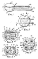
- Wire pair connector 10 includes a housing 12 comprising cap portion 14 and base portion 16 .
- a first pair of wires 18a and 18b enter cap 14
- a second pair of wires 20a and 20b enter base 16 .
- Each of the wires consists of a central metal core (typically copper) surrounded by an insulative layer (typically polypropylene or polyethylene).
- wires 18a and 18b enter channels 22a and 22b , respectively, in cap 14
- wires 20a and 20b enter channels 24a and 24b , respectively, of base 16
- All of these channels are generally parallel, channel 22a being directly over channel 24a
- channel 22b being directly over channel 24b
- the channels do not run completely through cap 14 or base 16 , but rather terminate within housing 12 to provide only one access port for each channel.
- cap 14 and base 16 are both generally cylindrical (although they need not be), and are constructed of any durable material such as polypropylene. Cap 14 and base 16 may be injection molded.
- the size of housing 12 depends on the gauge of the wires to be connected, which may be in the range of 10 to 30 AWG. For example, for 20 gauge wire, it is anticipated that cap 14 would have an outer diameter of about 10 millimeters, base 16 would have an outer diameter of about 8 mm, and the combination would have a height of about 10 mm. These values are not, however, intended to be limiting.
- Cap 14 includes an integral cuff portion 26 having an inner diameter approximately equal to the outer diameter of base 16 .
- Cuff 26 has two inner annular grooves 28 and 30 designed to fit with an annular flange 32 on base 16 .
- Cap 14 and base 16 also have complementary slots 34 and 36 for receiving H-shaped contact elements. While there are two such elements, only one element 38 is visible in the drawings, positioned in slot 36 .
- the contact elements must be electrically conductive, and are preferably constructed of a copper alloy, such as cartridge brass. Slot 34 extends from channel 22a to channel 24a , while slot 36 extends from channel 22b to channel 24b .
- the primary novelty of the present invention lies in the provision of reservoirs or voids adjacent to, and in fluid communication with, the channels in housing 12 .
- voids 40 , 42 , 44 and 46 there are four such voids (one for each channel), namely, voids 40 , 42 , 44 and 46 .
- the voids actually surround the channels.
- Each of these voids is filled with a conformable sealing material 48 .
- Sealing material 48 may take on a wide variety of characteristics depending upon the particular application made of wire pair connector 10 . It is, however, preferably viscous, electrically insulative, and moisture resistant. For most applications, a mastic is sufficient, such as polyisobutylene, ethylene propylene rubber, butyl rubber or mixtures of these compositions. Other materials may be used, such as caulk, silicone grease, cured or uncured elastomers having processing oils or rubber modifiers, liquid elastomers, plasticizers, modified plastisols, or dielectric fillers (this list is not exhaustive).
- annular flange 32 is abutting groove 28 , providing a clearance of about 2 millimeters between the top of base 16 and the bottom of cap 14 .
- Each of the voids opens toward this clearance space.
- piston 50 underlies void 42
- piston 52 overlies void 46
- piston 54 overlies void 44
- the fourth piston (not shown) underlies void 40 .
- Housing 12 is illustrated in an "open" position in Figures 3 and 4.
- contact element 38 Prior to installation of the wires, contact element 38 is clear of channels 22b and 24b (as best seen in Figure 4), and the second contact element (not shown) is clear of channels 22a and 24a .
- This allows the wires to be fully inserted into the channels.
- cap 14 and base 16 are squeezed together, as shown in Figure 5, which corresponds to the "closed" position of housing 12 .
- H-element 38 captures wires 18b and 20b , stripping a portion of the insulating layer away, thereby making electrical contact between said wires.
- the second H-element similarly makes contact between wires 18a and 20a .
- each of the pistons enters its corresponding void, forcing sealing material 48 down the channels, providing a reliable seal between the wire and cap 14 or base 16 .
- the voids are located intermediate the H-elements and the entries to each of the channels, this results in an environmental seal which precludes any entry of moisture or other contaminants through the channels which might adversely affect the connection at the H-elements. If a mastic sealant is used, the seal thus formed may also provide strain relief, and tends to hold cap 14 and base 16 together.
- the final step in closing housing 12 is the engagement of annular flange 32 into groove 30 in an interference fit, which provides a tight seal between cap 14 and base 16 (as well as holding them together).
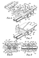
- FIGS. 6 through 9 illustrate the tap connector embodiment 60 of the present invention.
- the basic construction of tap connector 60 is similar to that disclosed in U.S. Patent No. 3,793,611 issued to Johansson et al. on February 19, 1974.
- Tap connector 60 includes a housing 62 , a cover 64 , and a retaining wall 66 connected to housing 62 by a living hinge 68 and connected to cover 64 by another living hinge 70 .
- the sise of tap connector 60 will again vary according to the gauge of the wires being connected; approximate dimensions for 20 gauge wire are 15 mm x 15 mm x 8 mm.
- Housing 62 has two channels 72 and 74 therein for receiving run wire 76 and tap wire 78 , respectively. There is only one entry to channel 74 (i.e., wire 78 terminates within housing 62 ), but channel 72 is open along one side to allow lateral placement of the run wire 76 .
- Housing 62 includes a collar portion 80 which provides strain relief. Another collar (not shown) may be provided on the other side of housing 62 for run wire 76 .
- a slot 82 is also provided in housing 62 for receiving an M-shaped contact element 84 .
- the primary novelty in tap connector 60 lies in the provision of four voids 86 in housing 62 which are in fluid communication with channels 72 and 74 .
- Voids 86 are exposed along the upper surface 92 of housing 62 , and are filled with the same sealing material 48 .
- one of the voids 86a extends fully to slot 82 , and the corresponding post 88a is larger than the other posts 88 . This allows simplified construction of housing 62 using injection molding techniques.
- Tap connector 60 is shown in the open state in Figure 6, while Figures 7 through 9 depict the closed state thereof.
- M-element 84 is urged into slot 82 and strips away a portion of the insulating layer around wires 76 and 78 , providing an electrical connection therebetween.
- posts 88 enter voids 86 , packing sealing material around the wires on either side of M-element 84 .
- the connection interface between M-element 84 and the wires is thereby completely sealed against environmental influences.
- Retaining wall 66 which may include a bump or boss 94 for positioning run wire 76 in channel 72 , is held in place by an integral flange portion 96 which snaps into a notch 98 in housing 62 .
- Cover 64 is similarly attached to housing 62 by means of an integral clip portion 100 which fits over the edge 102 of housing 62 .
- post and “piston” should not be construed as limiting. Rather, the invention contemplates the use of any means to force, squeeze or pack sealing material 48 from the voids into the channels and around the wires.
- wire pair connector 10 might easily be modified for interconnection of two wires only, or for connection of a three-wire group to another three-wire group.
- the invention is not limited to use on insulated wires, but may be used on wires which have a portion of the insulating layer already stripped away. It is therefore contemplated that the appended claims will cover such modifications that fall within the true scope of the invention.
Landscapes
- Chemical & Material Sciences (AREA)
- Dispersion Chemistry (AREA)
- Connector Housings Or Holding Contact Members (AREA)
- Connections By Means Of Piercing Elements, Nuts, Or Screws (AREA)
Applications Claiming Priority (2)
| Application Number | Priority Date | Filing Date | Title |
|---|---|---|---|
| US430863 | 1989-11-01 | ||
| US07/430,863 US4954098A (en) | 1989-11-01 | 1989-11-01 | Sealed insulation displacement connector |
Publications (2)
| Publication Number | Publication Date |
|---|---|
| EP0426384A1 true EP0426384A1 (de) | 1991-05-08 |
| EP0426384B1 EP0426384B1 (de) | 1994-10-12 |
Family
ID=23709386
Family Applications (1)
| Application Number | Title | Priority Date | Filing Date |
|---|---|---|---|
| EP90311745A Expired - Lifetime EP0426384B1 (de) | 1989-11-01 | 1990-10-26 | Abgedichteter Verbinder mit Isolierungsabsetzung |
Country Status (7)
| Country | Link |
|---|---|
| US (1) | US4954098A (de) |
| EP (1) | EP0426384B1 (de) |
| JP (1) | JP2869177B2 (de) |
| KR (1) | KR0177517B1 (de) |
| CA (1) | CA2026303A1 (de) |
| DE (1) | DE69013290T2 (de) |
| MY (1) | MY109725A (de) |
Cited By (5)
| Publication number | Priority date | Publication date | Assignee | Title |
|---|---|---|---|---|
| WO1993023960A3 (en) * | 1992-05-12 | 1994-01-20 | Raychem Corp | Telecommunications network interface assembly |
| EP0646987A1 (de) * | 1993-09-28 | 1995-04-05 | Alcatel Cable Interface | Verbindungsvorrichtung mit verbesserter Zuverlässigkeit |
| EP0818853A3 (de) * | 1996-07-09 | 1999-03-10 | Siemens Aktiengesellschaft | Zündpillen-Steckverbindung |
| FR2795241A1 (fr) * | 1999-06-16 | 2000-12-22 | Cinch Connecteurs Sa | Dispositif de liaison electrique entre un conducteur electrique principal et au moins un conducteur electrique secondaire |
| CN1083168C (zh) * | 1993-12-01 | 2002-04-17 | Nv雷伊化学有限公司 | 密封装置 |
Families Citing this family (40)
| Publication number | Priority date | Publication date | Assignee | Title |
|---|---|---|---|---|
| CA2010074C (en) * | 1989-03-29 | 2001-02-13 | Gilbert Roland Farnham | Valve assembly |
| US5176106A (en) * | 1990-10-31 | 1993-01-05 | Minnesota Mining And Manufacturing Company | Animal collar having a closable clasp |
| US5080606A (en) * | 1990-11-05 | 1992-01-14 | Minnesota Mining And Manufacturing Company | Stacked in-line insulation displacement connector |
| US5090917A (en) * | 1991-05-10 | 1992-02-25 | Thomas & Betts Corporation | Insulation displacing connector for providing repeatable sealed termination of electrical conductors |
| US5147217A (en) * | 1991-06-18 | 1992-09-15 | General Motors Corporation | Electrical component package |
| EP0871242A1 (de) * | 1991-10-11 | 1998-10-14 | Raychem Corporation | Anschlussleiste für die Fernmeldetechnik |
| US5557250A (en) * | 1991-10-11 | 1996-09-17 | Raychem Corporation | Telecommunications terminal block |
| US6302723B1 (en) | 1991-10-11 | 2001-10-16 | Tyco Electronics Corporation | Telecommunications terminal block |
| US5295857A (en) * | 1992-12-23 | 1994-03-22 | Toly Elde V | Electrical connector with improved wire termination system |
| GB9313281D0 (en) * | 1993-06-28 | 1993-08-11 | Amp Gmbh | Sealed insulation displacement connector |
| US5510153A (en) * | 1993-08-04 | 1996-04-23 | At&T Ipm Corporation | Method for encapsulating electronic conductors |
| DE4336849C1 (de) * | 1993-10-28 | 1995-01-05 | Rose Walter Gmbh & Co Kg | Verfahren zur Abdichtung von Kabeleinführungen unter Einsatz eines Dichtgeles |
| GB9324612D0 (en) * | 1993-12-01 | 1994-01-19 | Raychem Sa Nv | Environmental seal |
| US5626489A (en) * | 1995-04-13 | 1997-05-06 | Molex Incorporated | Sealed electrical connector assembly |
| GB9510886D0 (en) * | 1995-05-30 | 1995-07-26 | Amp Great Britain | Wire cutting electrical connector having test probe access |
| US6755676B2 (en) * | 1995-07-07 | 2004-06-29 | Henry Milan | Modular outlet strip |
| US5658158A (en) | 1995-08-28 | 1997-08-19 | Milan; Henry | Modular surge protection system with interchangeable surge protection modules |
| US5742223A (en) | 1995-12-07 | 1998-04-21 | Raychem Corporation | Laminar non-linear device with magnetically aligned particles |
| ZA976987B (en) * | 1996-08-16 | 1999-12-13 | Molex Inc | Electrical tap-off connector. |
| FR2757323B1 (fr) * | 1996-12-17 | 1999-01-22 | Schneider Electric Sa | Canalisation de distribution electrique a bus de transmission |
| DE19741603A1 (de) * | 1997-09-20 | 1999-03-25 | Volkswagen Ag | Elektrische Kontakteinrichtung sowie Verfahren zur Schneidkontaktherstellung |
| JP2000323195A (ja) * | 1999-05-14 | 2000-11-24 | Sumitomo Wiring Syst Ltd | 圧接コネクタ |
| US6080006A (en) * | 1999-05-26 | 2000-06-27 | Broder; Eric S. | Insulated connector for electrical conductors |
| JP2002158046A (ja) * | 2000-11-17 | 2002-05-31 | Yazaki Corp | 補機モジュール |
| US7059889B1 (en) * | 2005-10-12 | 2006-06-13 | Lear Corporation | Splice block for interconnecting electrical conductors |
| US7416434B2 (en) * | 2006-10-05 | 2008-08-26 | Lumination Llc | IDC splice connector |
| US7477826B2 (en) | 2007-01-16 | 2009-01-13 | Tyco Electronics Corporation | Cable enclosure assemblies and methods for using the same |
| DE102008013317B4 (de) * | 2008-03-10 | 2010-10-14 | Adc Gmbh | Verfahren zur Herstellung einer Aderanschlussleiste mit Gelfüllung |
| US8718434B2 (en) * | 2008-07-01 | 2014-05-06 | Adc Telecommunications, Inc. | Cable enclosure with sealed cable entry port |
| US7985094B2 (en) * | 2008-09-15 | 2011-07-26 | Adc Gmbh | Connector block |
| DE102012000079B4 (de) | 2012-01-04 | 2024-08-14 | Phoenix Contact Gmbh & Co. Kg | Elektrischer Dornverbinder sowie dessen Verwendung |
| US9543729B2 (en) * | 2013-08-19 | 2017-01-10 | Sullstar Technologies, Inc | Electrical connector with removable external load bar, and method of its use |
| CN106233533B (zh) * | 2015-02-20 | 2019-12-20 | J.S.T.公司 | 具有连接器位置保证装置的连接器 |
| US10014618B2 (en) * | 2015-02-20 | 2018-07-03 | J.S.T. Corporation | Connector with terminal position assurance |
| JP6952462B2 (ja) * | 2016-12-15 | 2021-10-20 | スリーエム イノベイティブ プロパティズ カンパニー | 電線収容体、コネクタアセンブリ、及び防水性コネクタ |
| EP3605742B1 (de) * | 2017-03-22 | 2025-03-26 | Kyocera Corporation | Verbinder |
| US10541478B1 (en) * | 2017-10-04 | 2020-01-21 | The Patent Store, Llc | Insulation displacement connector |
| CN108899660B (zh) * | 2018-07-05 | 2020-05-15 | 菲尼克斯亚太电气(南京)有限公司 | 一种idc免剥线接线机构 |
| CN110137708A (zh) * | 2019-04-30 | 2019-08-16 | 上海顿格电子贸易有限公司 | 一种接线器 |
| US11515696B2 (en) * | 2019-12-17 | 2022-11-29 | Te Connectivity Solutions Gmbh | Electrical component enclosure with injected seal and method |
Citations (3)
| Publication number | Priority date | Publication date | Assignee | Title |
|---|---|---|---|---|
| US4326767A (en) * | 1979-03-12 | 1982-04-27 | Minnesota Mining And Manufacturing Company | Wire cutting electrical connector |
| EP0095307A1 (de) * | 1982-05-24 | 1983-11-30 | Minnesota Mining And Manufacturing Company | Elektrischer Drahtverbinder |
| GB2161994A (en) * | 1984-06-20 | 1986-01-22 | Trw Carr Ltd | Insulation displacement connector assembly |
Family Cites Families (31)
| Publication number | Priority date | Publication date | Assignee | Title |
|---|---|---|---|---|
| US3012219A (en) * | 1959-03-19 | 1961-12-05 | Minnesota Mining & Mfg | Solderless connector for insulated small wires |
| US3258733A (en) * | 1959-03-19 | 1966-06-28 | Wire connector | |
| NL266293A (de) * | 1960-06-23 | |||
| US3202957A (en) * | 1962-04-30 | 1965-08-24 | Minnesota Mining & Mfg | Wire-cutting solderless connector |
| US3388370A (en) * | 1966-04-14 | 1968-06-11 | Minnesota Mining & Mfg | Solderless connector for insulated wires |
| US3410950A (en) * | 1966-06-01 | 1968-11-12 | Amp Inc | Insulated moisture-proof connecting device |
| US3500292A (en) * | 1968-07-12 | 1970-03-10 | Minnesota Mining & Mfg | Wire-connector |
| US3576518A (en) * | 1968-11-07 | 1971-04-27 | Minnesota Mining & Mfg | Solderless connector for insulated wires |
| US3573713A (en) * | 1968-11-21 | 1971-04-06 | Minnesota Mining & Mfg | Connector |
| US3605072A (en) * | 1969-02-28 | 1971-09-14 | Minnesota Mining & Mfg | Solderless wire connector |
| US3609644A (en) * | 1969-10-20 | 1971-09-28 | Minnesota Mining & Mfg | Main frame connector and method |
| US3656088A (en) * | 1970-07-27 | 1972-04-11 | Minnesota Mining & Mfg | Connector |
| US3804971A (en) * | 1971-06-28 | 1974-04-16 | Minnesota Mining & Mfg | Solderless wire connector |
| US3723948A (en) * | 1971-11-08 | 1973-03-27 | Minnesota Mining & Mfg | Electrical component |
| US3793612A (en) * | 1972-03-02 | 1974-02-19 | Minnesota Mining & Mfg | Connector with unitary hinge |
| US3793611A (en) * | 1972-03-02 | 1974-02-19 | Minnesota Mining & Mfg | Connector |
| US3845236A (en) * | 1973-06-21 | 1974-10-29 | Minnesota Mining & Mfg | Wire connector |
| US3858157A (en) * | 1974-02-19 | 1974-12-31 | Minnesota Mining & Mfg | Solderless tap connector |
| US3869190A (en) * | 1974-03-29 | 1975-03-04 | Minnesota Mining & Mfg | Solderless wire connector |
| US3912356A (en) * | 1974-05-28 | 1975-10-14 | Minnesota Mining & Mfg | Solderless connector |
| US3949467A (en) * | 1974-08-05 | 1976-04-13 | Minnesota Mining And Manufacturing Company | Solderless electrical connector element application method and apparatus |
| US4124265A (en) * | 1977-11-10 | 1978-11-07 | Minnesota Mining And Manufacturing Company | Quick slide connector |
| US4444448A (en) * | 1980-01-14 | 1984-04-24 | Minnesota Mining And Manufacturing Company | Wire cutting electrical connector |
| DE3110144C2 (de) * | 1981-03-16 | 1983-05-19 | Minnesota Mining and Manufacturing Co., 55133 Saint Paul, Minn. | Zugentlastung elektrischer Leiter in einem elektrischen Verbinder für nicht abisolierte Leiter |
| GB2101420B (en) * | 1981-06-25 | 1985-03-27 | Standard Telephones Cables Ltd | Waterproof connector |
| US4435034A (en) * | 1981-10-08 | 1984-03-06 | Northern Telecom Limited | Connectors with insulation-displacing terminals |
| US4496206A (en) * | 1982-05-24 | 1985-01-29 | Minnesota Mining And Manufacturing Company | Side entry electrical wire connector |
| US4552429A (en) * | 1984-10-01 | 1985-11-12 | Amp Incorporated | Modular electrical connector for connecting wires in cable ends |
| EP0209046A3 (de) * | 1985-07-10 | 1989-07-26 | Siemens Aktiengesellschaft | Verzweigergehäuse für Nachrichtenkabel |
| FR2585192A1 (fr) * | 1985-07-18 | 1987-01-23 | Auxiliaire Appar Electric | Connecteur electrique destine a realiser une derivation electrique a partir d'un cable electrique forme d'un conducteur entoure d'une gaine isolante |
| JPH084020B2 (ja) * | 1987-02-20 | 1996-01-17 | ミネソタ マイニング アンド マニユフアクチユアリング カンパニ− | 電話ケ−ブル用のコネクタ |
-
1989
- 1989-11-01 US US07/430,863 patent/US4954098A/en not_active Expired - Fee Related
-
1990
- 1990-09-26 CA CA002026303A patent/CA2026303A1/en not_active Abandoned
- 1990-10-02 MY MYPI90001704A patent/MY109725A/en unknown
- 1990-10-26 DE DE69013290T patent/DE69013290T2/de not_active Expired - Fee Related
- 1990-10-26 EP EP90311745A patent/EP0426384B1/de not_active Expired - Lifetime
- 1990-10-31 JP JP2295143A patent/JP2869177B2/ja not_active Expired - Lifetime
- 1990-10-31 KR KR1019900017548A patent/KR0177517B1/ko not_active Expired - Fee Related
Patent Citations (3)
| Publication number | Priority date | Publication date | Assignee | Title |
|---|---|---|---|---|
| US4326767A (en) * | 1979-03-12 | 1982-04-27 | Minnesota Mining And Manufacturing Company | Wire cutting electrical connector |
| EP0095307A1 (de) * | 1982-05-24 | 1983-11-30 | Minnesota Mining And Manufacturing Company | Elektrischer Drahtverbinder |
| GB2161994A (en) * | 1984-06-20 | 1986-01-22 | Trw Carr Ltd | Insulation displacement connector assembly |
Cited By (8)
| Publication number | Priority date | Publication date | Assignee | Title |
|---|---|---|---|---|
| WO1993023960A3 (en) * | 1992-05-12 | 1994-01-20 | Raychem Corp | Telecommunications network interface assembly |
| US5359654A (en) * | 1992-05-12 | 1994-10-25 | Raychem Corporation | Telecommunications network interface assembly |
| EP0646987A1 (de) * | 1993-09-28 | 1995-04-05 | Alcatel Cable Interface | Verbindungsvorrichtung mit verbesserter Zuverlässigkeit |
| FR2710785A1 (fr) * | 1993-09-28 | 1995-04-07 | Alcatel Cable Interface | Dispositif de raccordement fiabilisé. |
| CN1083168C (zh) * | 1993-12-01 | 2002-04-17 | Nv雷伊化学有限公司 | 密封装置 |
| EP0818853A3 (de) * | 1996-07-09 | 1999-03-10 | Siemens Aktiengesellschaft | Zündpillen-Steckverbindung |
| KR100510603B1 (ko) * | 1996-07-09 | 2005-12-26 | 지멘스 악티엔게젤샤프트 | 프라이머를 갖춘 플러그 타입 커넥터 |
| FR2795241A1 (fr) * | 1999-06-16 | 2000-12-22 | Cinch Connecteurs Sa | Dispositif de liaison electrique entre un conducteur electrique principal et au moins un conducteur electrique secondaire |
Also Published As
| Publication number | Publication date |
|---|---|
| DE69013290D1 (de) | 1994-11-17 |
| KR0177517B1 (ko) | 1999-05-15 |
| US4954098A (en) | 1990-09-04 |
| KR910010772A (ko) | 1991-06-29 |
| CA2026303A1 (en) | 1991-05-02 |
| JP2869177B2 (ja) | 1999-03-10 |
| MY109725A (en) | 1997-05-31 |
| DE69013290T2 (de) | 1995-05-11 |
| JPH03155068A (ja) | 1991-07-03 |
| EP0426384B1 (de) | 1994-10-12 |
Similar Documents
| Publication | Publication Date | Title |
|---|---|---|
| EP0426384B1 (de) | Abgedichteter Verbinder mit Isolierungsabsetzung | |
| EP0556265B1 (de) | Durchgehender schneidklemmenverbinder mit verschobenen reihen | |
| JP2539326B2 (ja) | 端子ブロック | |
| JP3518799B2 (ja) | 電線モジュール | |
| US4157208A (en) | Waterproof splice electrical connector | |
| US5626489A (en) | Sealed electrical connector assembly | |
| US9147961B2 (en) | Method of forming waterproof electrical connections | |
| EP0631344B1 (de) | Abgedichteter Schneidklemmverbinder | |
| US3897129A (en) | Connector encapsulating device and method | |
| US4446332A (en) | Wire connector | |
| US6074240A (en) | Terminal block | |
| US7309256B2 (en) | Flat flexible cable assembly with integrally-formed sealing members | |
| US20190157776A1 (en) | Pass-through cable connector assembly and method of making the same | |
| JPH07201395A (ja) | コネクタ | |
| WO1998016970A9 (en) | Terminal block | |
| US5100347A (en) | Method and apparatus for providing a cable assembly seal and strain relief | |
| CN220857043U (zh) | 防水效果好的连接器 | |
| US4372637A (en) | Bond shield terminal | |
| US5888091A (en) | Termination of an insulated electrical conductor | |
| US5911598A (en) | Electrical connector with protective gel | |
| JP2515978Y2 (ja) | 圧接ジヨイントコネクタ | |
| JP2001155792A (ja) | 圧接ジョイント端子及びコネクタ | |
| GB2094569A (en) | A moulded electrical connector | |
| JPH06243913A (ja) | 電線接続部の防水構造 | |
| JP3183391B2 (ja) | オートマチックトランスミッション用ハーネスのシーリング構造 |
Legal Events
| Date | Code | Title | Description |
|---|---|---|---|
| PUAI | Public reference made under article 153(3) epc to a published international application that has entered the european phase |
Free format text: ORIGINAL CODE: 0009012 |
|
| 17P | Request for examination filed |
Effective date: 19901120 |
|
| AK | Designated contracting states |
Kind code of ref document: A1 Designated state(s): DE FR GB IT SE |
|
| 17Q | First examination report despatched |
Effective date: 19930222 |
|
| GRAA | (expected) grant |
Free format text: ORIGINAL CODE: 0009210 |
|
| ITF | It: translation for a ep patent filed | ||
| AK | Designated contracting states |
Kind code of ref document: B1 Designated state(s): DE FR GB IT SE |
|
| REF | Corresponds to: |
Ref document number: 69013290 Country of ref document: DE Date of ref document: 19941117 |
|
| ET | Fr: translation filed | ||
| EAL | Se: european patent in force in sweden |
Ref document number: 90311745.5 |
|
| PLBE | No opposition filed within time limit |
Free format text: ORIGINAL CODE: 0009261 |
|
| STAA | Information on the status of an ep patent application or granted ep patent |
Free format text: STATUS: NO OPPOSITION FILED WITHIN TIME LIMIT |
|
| 26N | No opposition filed | ||
| PGFP | Annual fee paid to national office [announced via postgrant information from national office to epo] |
Ref country code: FR Payment date: 19980930 Year of fee payment: 9 |
|
| PGFP | Annual fee paid to national office [announced via postgrant information from national office to epo] |
Ref country code: SE Payment date: 19981001 Year of fee payment: 9 |
|
| PGFP | Annual fee paid to national office [announced via postgrant information from national office to epo] |
Ref country code: DE Payment date: 19981002 Year of fee payment: 9 |
|
| PGFP | Annual fee paid to national office [announced via postgrant information from national office to epo] |
Ref country code: GB Payment date: 19981015 Year of fee payment: 9 |
|
| PG25 | Lapsed in a contracting state [announced via postgrant information from national office to epo] |
Ref country code: GB Free format text: LAPSE BECAUSE OF NON-PAYMENT OF DUE FEES Effective date: 19991026 |
|
| PG25 | Lapsed in a contracting state [announced via postgrant information from national office to epo] |
Ref country code: SE Free format text: THE PATENT HAS BEEN ANNULLED BY A DECISION OF A NATIONAL AUTHORITY Effective date: 19991030 |
|
| GBPC | Gb: european patent ceased through non-payment of renewal fee |
Effective date: 19991026 |
|
| EUG | Se: european patent has lapsed |
Ref document number: 90311745.5 |
|
| PG25 | Lapsed in a contracting state [announced via postgrant information from national office to epo] |
Ref country code: FR Free format text: LAPSE BECAUSE OF NON-PAYMENT OF DUE FEES Effective date: 20000630 |
|
| PG25 | Lapsed in a contracting state [announced via postgrant information from national office to epo] |
Ref country code: DE Free format text: LAPSE BECAUSE OF NON-PAYMENT OF DUE FEES Effective date: 20000801 |
|
| REG | Reference to a national code |
Ref country code: FR Ref legal event code: ST |
|
| PG25 | Lapsed in a contracting state [announced via postgrant information from national office to epo] |
Ref country code: IT Free format text: LAPSE BECAUSE OF NON-PAYMENT OF DUE FEES Effective date: 20051026 |