EP0426538B1 - Elektrischer Schalter für die kombinierte Betätigung der Scheinwerfer und zumindest einer Nebelschlussleuchte eines Kraftfahrzeugs - Google Patents
Elektrischer Schalter für die kombinierte Betätigung der Scheinwerfer und zumindest einer Nebelschlussleuchte eines Kraftfahrzeugs Download PDFInfo
- Publication number
- EP0426538B1 EP0426538B1 EP19900403020 EP90403020A EP0426538B1 EP 0426538 B1 EP0426538 B1 EP 0426538B1 EP 19900403020 EP19900403020 EP 19900403020 EP 90403020 A EP90403020 A EP 90403020A EP 0426538 B1 EP0426538 B1 EP 0426538B1
- Authority
- EP
- European Patent Office
- Prior art keywords
- selector
- main
- ramp means
- bav
- bar
- Prior art date
- Legal status (The legal status is an assumption and is not a legal conclusion. Google has not performed a legal analysis and makes no representation as to the accuracy of the status listed.)
- Expired - Lifetime
Links
- 241001465382 Physalis alkekengi Species 0.000 description 6
- 238000010586 diagram Methods 0.000 description 4
- 230000001131 transforming effect Effects 0.000 description 2
- 239000004020 conductor Substances 0.000 description 1
- 230000000149 penetrating effect Effects 0.000 description 1
- 230000007704 transition Effects 0.000 description 1
Images


Classifications
-
- B—PERFORMING OPERATIONS; TRANSPORTING
- B60—VEHICLES IN GENERAL
- B60Q—ARRANGEMENT OF SIGNALLING OR LIGHTING DEVICES, THE MOUNTING OR SUPPORTING THEREOF OR CIRCUITS THEREFOR, FOR VEHICLES IN GENERAL
- B60Q1/00—Arrangement of optical signalling or lighting devices, the mounting or supporting thereof or circuits therefor
- B60Q1/02—Arrangement of optical signalling or lighting devices, the mounting or supporting thereof or circuits therefor the devices being primarily intended to illuminate the way ahead or to illuminate other areas of way or environments
- B60Q1/04—Arrangement of optical signalling or lighting devices, the mounting or supporting thereof or circuits therefor the devices being primarily intended to illuminate the way ahead or to illuminate other areas of way or environments the devices being headlights
- B60Q1/14—Arrangement of optical signalling or lighting devices, the mounting or supporting thereof or circuits therefor the devices being primarily intended to illuminate the way ahead or to illuminate other areas of way or environments the devices being headlights having dimming means
- B60Q1/1446—Arrangement of optical signalling or lighting devices, the mounting or supporting thereof or circuits therefor the devices being primarily intended to illuminate the way ahead or to illuminate other areas of way or environments the devices being headlights having dimming means controlled by mechanically actuated switches
- B60Q1/1453—Hand actuated switches
- B60Q1/1461—Multifunction switches for dimming headlights and controlling additional devices, e.g. for controlling direction indicating lights
- B60Q1/1469—Multifunction switches for dimming headlights and controlling additional devices, e.g. for controlling direction indicating lights controlled by or attached to a single lever, e.g. steering column stalk switches
- B60Q1/1476—Multifunction switches for dimming headlights and controlling additional devices, e.g. for controlling direction indicating lights controlled by or attached to a single lever, e.g. steering column stalk switches comprising switch controlling means located near the free end of the lever, e.g. press buttons, rotatable rings
-
- H—ELECTRICITY
- H01—ELECTRIC ELEMENTS
- H01H—ELECTRIC SWITCHES; RELAYS; SELECTORS; EMERGENCY PROTECTIVE DEVICES
- H01H25/00—Switches with compound movement of handle or other operating part
- H01H25/06—Operating part movable both angularly and rectilinearly, the rectilinear movement being along the axis of angular movement
- H01H25/065—Operating part movable both angularly and rectilinearly, the rectilinear movement being along the axis of angular movement using separate operating parts, e.g. a push button surrounded by a rotating knob
Definitions
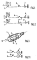
- the present relates to an electric switch, for the combined control of the main lighting lights and the front and rear fog lights of a motor vehicle, of the type comprising a lighting selector switch for the main lights in so-called city-stop positions.
- road rotatably mounted in a housing, a light selector of at least one rear fog light, and a light selector of at least one front fog light.
- a motor vehicle has two front fog lights (or headlamps) and at least one rear fog light (or headlamp).
- the use of the front fog light is authorized when the main lights lighting selector is in city position (lanterns) or in road position (code / headlight) ), the use of the rear fog lamp is only authorized as above, when the main lights lighting selector is in the high position and when the front fog lamp is on.
- Reference 2 represents the rear fog lamp selector and reference 4 represents the front fog lamp selector, references 3 and 5 respectively designating the rear fog lamp and the front fog light.
- the switch comprises a control shaft with a portion provided with two diametrically opposite axial grooves to cooperate with indexing balls, which the switch has for determination of the stop-town-route positions of the main lighting selector.
- Circumferential grooves are provided inside the axial grooves to allow control of at least one fog light.
- the object of the present invention is to overcome these drawbacks and therefore to create a new arrangement which, in a simple and economical manner, makes it possible to reset the control of the rear fog light in all the configurations where its use is authorized.
- the contacts of the main light selector switch are less stressed.
- said cursor is housed inside the button that the lighting selector for the main lights presents.
- said slider can be mounted in end of the joystick in place of the horn button, the cursor then carrying a rod capable of cooperating with an electric track disposed inside a support on which said joystick is articulated, which reduces the number switch wires.
- the electric switch for the combined control of the main lighting lights, and the rear and front fog lights of a motor vehicle comprises a lighting selector 1 of the main lights with positions called stop-town-drive, here said for convenience selector main, as well as a lighting selector 2, at least one rear fog light, said here for convenience of selector BAR.
- the main selector 1 is rotatably mounted in a housing 11, and it will be assumed here, for simplicity, that two rear fog lights are provided.
- the vehicle may include only a rear fog light associated with a reversing light.
- the switch also comprises a lighting selector 4 of at least one front fog light, said here for convenience, BAV selector.
- This BAV selector is rotatably mounted coaxially with respect to the main selector 1.
- the axis of rotation of the BAV selector coincides with the axis of rotation of the main selector.
- the vehicle has two front fog lights, it being understood, for example in the case of a motorcycle, that only one front fog light can exist.
- the main selector 1 can occupy three positions, namely, position O (Stop), position V (City), position R (Road).
- the BAR selector makes it possible to control or not the auxiliary rear fog lights (abbreviation BAR in Figure 6).
- the BAV selector allows to control or not the auxiliary front fog lights (abbreviation BAV to Figure 6).
- the main selector 1 carries a slider 35, on the one hand, belonging to the selector BAR 2 and, on the other hand, mounted movable in translation relative to the axis of rotation of said main selector, between an initial position and a control position for which the rear fog lights are respectively switched off and on.
- Said cursor 35 carries a projection 33 capable of cooperating with first ramp means 60, 52, 70 carried by the housing 11 of said main selector 1.
- the BAV selector 4 also carries a projection 40 capable of cooperating with second ramp means 51 carried by said housing 11.
- a movable intermediate piece 50 partially carries said first and second ramp means and is interposed between, seen in the direction of the axis of rotation of the main selector 1, said projections 33.40 of the slider 35 and of the selector BAV 4.
- the selector BAR 2 of the rear fog light (s) is reset, when the main selector 1 returns to the off position.
- Said selector BAR 2 is also reset, when the main selector 1 being in the city position, the selector BAV 4 returns to the initial position.
- the first ramp means 60, 52, 70 comprise at least one fixed part 60 secured to the housing 11.
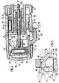
- the switch is part of a lever 10 available to the driver.
- This lever also serves to control the direction indicator lights and comprises a fixed housing 11 in the form of a tubular envelope.
- this envelope 11 comprises a bush 12 provided with a transverse shoulder 13.
- the housing 11 partially carries the selector at the end 1.
- the latter comprises a hollow rotary knob 7, provided with a nose 32 of tubular shape penetrating inside the socket 12 while being centered externally by the latter.
- the nose 32 internally carries a fastener 31 capable of driving contact pads (not visible) capable of cooperating with a connection circuit (not visible) for the supply, depending on the position of the selector 1, of the lanterns, codes and vehicle headlights.
- the coach 31 here consists of a sleeve.
- the button 7 is internally provided with ramp means 26, with which is capable of cooperating with a plunger 25 carried by the selector BAR 2.
- the button 7 has a light 34 for guiding the cursor 35.
- This cursor 35 has a part 36, forming a notched finger passing through the lumen 34 and extending outside the housing 11 and the button 7, to be operated in translation by the conductor.
- the cursor 35 has, on the one hand, a blind hole 27, inside which guide slides the plunger 25, biased by a spring 24 bearing on the bottom of said hole 27.
- This hole 27 extends perpendicularly to the axis XX ′ of symmetry of the housing 11 (see FIG. 4) and to the housing 17 parallel to said axis.
- the cursor 35 advantageously made of plastic, also has a blind hole 28, extending parallel to said axis XX ′, for housing the end of a rod 29 carrying at its other end a contact 30 to establish connections and supply or not the rear fog lights.
- connections belong to the support, on which the lever is mounted.
- the rod 29 is integral with the cursor 35, for example by being force-fitted into the hole 28.
- the free end of the button 7 is capped by a cap 21 forming a stop shoulder for the cursor 35.
- the ramp means 26 have, in section, a triangle shape and include a local imprint 23 with which the plunger 25 cooperates to define a stable initial position.
- the wall 8 comprises ramp means 16 extending circumferentially and axially for cooperation with the plunger 15 of axial orientation.
- the envelope 11 is provided internally, locally with an additional thickness for forming a fixed ramp 60.
- the socket 12 carries on the side of the wall 13 opposite the plunger 15 the BAV selector 4.
- This selector in the form of a knurled rotary button centered by the socket 12, has a projection 40 (FIG. 5) suitable for cooperating with an intermediate piece 50 which is movable axially.
- This part 50 has on its two lateral faces ramp means 51 and 52 respectively.
- the ramp means 51 belong to the second ramp means and are capable of cooperating with the projection 40.
- the ramp means 52 belong to the first ramp means and are suitable for cooperating with the projection 33.
- the part 50 is wider at its lower base (FIG. 5), the ramp 52 being suitable for covering the ramp 60 for certain configurations, as described below.
- the ramp 52 has an inclined upper portion and a lower vertical portion, while the ramp 51 has an upper vertical portion, a portion inclined median and a vertical lower portion ( Figure 5).
- the intermediate piece 50 is guided in translation by the edges of an opening 53 partially delimited by the housing 11 and by the sleeve 12, while being carried by said housing 11.
- This part 50 is therefore interposed axially between the projections 33 and 40, (here in the form of fingers) of axial orientation parallel to the axis X-X ′.
- the button 4 is also indexed in position by a plunger cooperating with ramp means in a manner similar to the plunger 15 and 25, said plunger being able to be of axial or radial orientation.
- This button 4 carries a pad suitable for establishing electrical connections.
- the BAR selector (FIG. 11) is connected directly to one of the terminals of the power source, here the + terminal of the battery, the pad 30 therefore being allowed to establish a connection with said terminal, while the associated pad the selector 4 is suitable for establishing a connection with the supply of the vehicle's lanterns (position V).
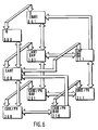
- FIGS. 6 and 7 The operation of the switch is carried out as more particularly visible in FIGS. 6 and 7, in which a number of three digits appears for each box.
- the first digit corresponds to the position of selector 1, its value being O for the O position, 1 for the V or LANT position, 2 for the R or CODE / PH position.
- the second digit is associated with the BAR selector, its value being either O (selector in the initial position) or 1 (selector in the control position).
- the third digit is associated with the BAV selector, its value being, as before, either O (selector in the initial position) or 1 (selector in the control position).
- Each box corresponds to a determined position of the selectors 1,2 and 4, and the connections between the boxes with double arrow are possible manually in both directions, while the connections with a single arrow are possible only in one direction, the selector BAR being locked in one direction by ramp means 60,51,52.
- the button 7 is turned to the position R indexed by the plunger 15, while the plunger 25 and the slider 35 are in their initial position (FIG. 4), just like the button 4, the fog lights being then turned off.
- box 210 the diver occupies the position shown in dotted lines in FIG. 4 and nothing prevents the driver from returning to box 200.
- part 50 is buttressed by the finger 40 and cannot move in the opposite direction from the projection 33.
- the intermediate piece 50 is also in the position of FIG. 5 and nothing prevents moving from the box OOO to the box 0 0 1 and vice versa, the piece 50 then being buttressed by projection 33.
- the ramp means according to the invention form locking means preventing the engagement of the rear fog lights, when the selector 1 is not in the code / headlight position and when the front fog lights are not engaged. .
- the ramp means allow a reset of the rear fog lights, when the main selector returns to its off position, or when in the city position, front fog lights engaged, the BAV selector returns to the initial position.
- the part 50 is mobile and covers in certain positions the ramp 60.
- the switch is identical to the previous one except that it does not include a selector 4.
- the ramp means 70 are fixed and are carried here by the sleeve 12.
- buttons 36 can be moved only when one is in the road position.
- the ramp means 70 comprise two parallel portions connected to each other by an inclined portion, one of the portions being associated with the road position, while the other is associated with the positions 0 and V. This is shown in FIG. 7 to be rendered fixes the part 50.
- the present invention is not limited to the examples of embodiment described, in particular the movable part 50 can be mounted under slight prestress to reduce noise, elastic means being, for example, interposed between said part 50 and the opening 53.
- the ramp means 52 may have only a vertical portion and an inclined portion.
- the BAV selector 4 may include an actuator movable in translation and associated with a device transforming the translational movement of said member into a rotational movement.
- the cursor BAR may include an actuating member movable in rotation and associated with a device transforming the rotational movement in translation, the finger 36 then no longer being necessary.
Landscapes
- Engineering & Computer Science (AREA)
- Mechanical Engineering (AREA)
- Lighting Device Outwards From Vehicle And Optical Signal (AREA)
- Switches With Compound Operations (AREA)
Claims (10)
- Elektrischer Schalter für die kombinierte Betätigung der Hauptscheinwerfer sowie der Nebelschlußleuchten und der Nebelscheinwerfer eines Kraftfahrzeugs, bestehend aus einem Beleuchtungswählschalter (1) für die Hauptscheinwerfer mit den Positionen 'Aus-Stadtlicht-Abblendlicht/Fernlicht', hier der Einfachheit halber als Hauptwählschalter bezeichnet, der drehbar in einem Gehäuse (11) eingebaut ist, einem Beleuchtungswählschalter für zumindest eine Nebelschlußleuchte (2), hier der Einfachheit halber als Nebelschlußleuchtenschalter bezeichnet, und einem Beleuchtungswählschalter für zumindest einen Nebelscheinwerfer (4), hier der Einfachheit halber als Nebelscheinwerferschalter bezeichnet, wobei der Nebelschlußleuchtenschalter (2) und der Nebelscheinwerferschalter (4) eine Ausgangsposition und eine Betätigungsposition einnehmen können, in welcher die Nebelschlußleuchte und der Nebelscheinwerfer ausgeschaltet bzw. eingeschaltet sind, dadurch gekennzeichnet, daß der Nebelschlußleuchtenschalter (2) einen am Hauptwählschalter (1) angebrachten Schieber (35) umfaßt, der im Verhältnis zum Hauptwählschalter (1) geradlinig beweglich zwischen den beiden Positionen des Nebelschlußleuchtenschalters (2) angeordnet ist, daß der Schieber (35) und der Nebelscheinwerferschalter (4), der im Verhältnis zum Hauptwählschalter (1) koaxial drehbar eingebaut ist, jeweils einen Vorsprung (33, 40) aufweisen, von denen jeder mit ersten Rampenmitteln (60, 52) bzw. zweiten Rampenmitteln (51) zusammenwirken kann, welche zumindest teilweise am Gehäuse (11) des Hauptwählschalters (1) angebracht sind, und daß ein bewegliches Zwischenstück (50), das zumindest teilweise die ersten und zweiten Rampenmittel trägt, - in Richtung der Drehachse des Hauptwählschalters (1) gesehen - zwischen den besagten Vorsprüngen (40, 33) des Nebelschlußleuchtenschalters (4) und des Nebelscheinwerferschalters (2) eingesetzt ist, so daß durch Zusammenwirken des Vorsprungs (33) des Schiebers (35) mit den ersten Rampenmitteln (69, 52) der Nebelschlußleuchtenschalter (2) reinitialisiert wird, wenn der Hauptwählschalter (1) in die Position 'Aus' zurückkehrt, und daß der Nebelschlußleuchtenschalter (2) reinitialisiert wird, wenn sich der Hauptwählschalter (1) in der Position 'Stadtlicht' befindet und der Nebelscheinwerferschalter (4) in die Ausgangsposition zurückkehrt.
- Schalter nach Anspruch 1 , dadurch gekennzeichnet, daß das Zwischenstück (50) durch das Gehäuse (11) des Hauptwählschalters (1) geradlinig geführt wird und daß dieses Zwischenstück (50) seitlich zumindest einen Teil der ersten und zweiten Rampenmittel (52, 51) aufweist.
- Schalter nach Anspruch 1 oder 2 , dadurch gekennzeichnet, daß die ersten Rampenmittel (60, 52) einen feststehenden Teil (60) umfassen, der fest mit dem Gehäuse (11) des Hauptwählschalters (1) verbunden ist, und daß das Zwischenstück (50) diesen feststehenden Teil (60) der ersten Rampenmittel (60, 52) überdecken kann.
- Schalter nach Anspruch 2 oder 3 , dadurch gekennzeichnet, daß die Rampenmittel (51, 52), die das Zwischenstück (50) seitlich aufweist, jeweils zumindest einen vertikalen Teil umfassen, an den sich ein abgeschrägter Teil anschließt, und daß die besagten vertikalen Teile parallel zueinander verlaufen, so daß das Zwischenstück (50) an einer seiner Grundflächen breiter ist.
- Schalter nach einem der Ansprüche 1 bis 4, bei dem der Hauptwählschalter (1) einen hohlen Knopf (7) umfaßt , dadurch gekennzeichnet, daß der Schieber (35) im Innern dieses Knopfes (7) angeordnet ist und daß er einen Finger (36) umfaßt, der durch einen in diesem Knopf (7) vorgesehenen Schlitz (34) hindurchgeht.
- Schalter nach Anspruch 5 , dadurch gekennzeichnet, daß der Schieber (35) ein Blindloch (27) für die gleitende Führung eines Stößels (25) umfaßt, der mit Rampenmitteln (26) zusammenwirken kann, die an dem Knopf (7) angebracht sind.
- Schalter nach Anspruch 5 oder 6, dadurch gekennzeichnet, daß der Schieber (35) ein zweites Blindloch (28) für den Einbau einer Stange (29) umfaßt, die mit einem Kontaktstift (30) verbunden ist und die durch eine Querwand (8) hindurchgeht, die der Knopf (7) aufweist.
- Schalter nach einem der Ansprüche 5 bis 7 , dadurch gekennzeichnet, daß der Knopf (7) eine Nase (32) aufweist, die mit einem Mitnehmer (31) verbunden ist, und daß diese Nase (32) durch eine fest mit dem Gehäuse (11) verbundene Hülse (12) geführt wird.
- Schalter nach einem der Ansprüche 1 bis 8 , dadurch gekennzeichnet, daß der Nebelscheinwerferschalter (4) einen Drehknopf aufweist, der über einen mit Rampenmitteln zusammenwirkenden Stößel verrastet ist.
- Schalter nach einem der vorangehenden Ansprüche, dadurch gekennzeichnet, daß die Vorsprünge (33, 40) des Nebelschlußleuchtenschalters (2) und des Nebelscheinwerferschalters (4) aus axial ausgerichteten Fingern bestehen.
Applications Claiming Priority (2)
| Application Number | Priority Date | Filing Date | Title |
|---|---|---|---|
| FR8914348 | 1989-11-02 | ||
| FR8914348A FR2653928B1 (fr) | 1989-11-02 | 1989-11-02 | Commutateur electrique pour la commande combinee des feux d'eclairage et d'au moins un feu anti-brouillard arriere, d'un vehicule automobile. |
Publications (2)
| Publication Number | Publication Date |
|---|---|
| EP0426538A1 EP0426538A1 (de) | 1991-05-08 |
| EP0426538B1 true EP0426538B1 (de) | 1994-11-30 |
Family
ID=9387011
Family Applications (1)
| Application Number | Title | Priority Date | Filing Date |
|---|---|---|---|
| EP19900403020 Expired - Lifetime EP0426538B1 (de) | 1989-11-02 | 1990-10-26 | Elektrischer Schalter für die kombinierte Betätigung der Scheinwerfer und zumindest einer Nebelschlussleuchte eines Kraftfahrzeugs |
Country Status (4)
| Country | Link |
|---|---|
| EP (1) | EP0426538B1 (de) |
| DE (1) | DE69014557T2 (de) |
| ES (1) | ES2066999T3 (de) |
| FR (1) | FR2653928B1 (de) |
Cited By (1)
| Publication number | Priority date | Publication date | Assignee | Title |
|---|---|---|---|---|
| DE10249817A1 (de) * | 2002-10-24 | 2004-05-13 | Daimlerchrysler Ag | Schaltanordnung zur Betätigung von Beleuchtungssystemen an einem Kraftfahrzeug |
Families Citing this family (12)
| Publication number | Priority date | Publication date | Assignee | Title |
|---|---|---|---|---|
| DE4210452C2 (de) * | 1992-03-30 | 1996-07-11 | Trw Messmer | Elektrischer Schalter, insbesondere Wischerschalter in einem Kraftfahrzeug |
| FR2737039B1 (fr) * | 1995-07-21 | 1997-10-10 | Magneti Marelli France | Commutateur electrique pour vehicules automobiles |
| JP3574709B2 (ja) * | 1996-01-18 | 2004-10-06 | ナイルス株式会社 | 自動車用複合スイッチレバー装置 |
| DE19601984A1 (de) * | 1996-01-20 | 1997-07-24 | Teves Gmbh Alfred | Drehschalter mit Zwischensperre zwischen den Drehschritten |
| FR2745944B1 (fr) * | 1996-03-11 | 1998-05-22 | Magneti Marelli France | Commutateur electrique pour vehicules automobiles pour la commande de feux anti-brouillard |
| JP3403583B2 (ja) * | 1996-06-25 | 2003-05-06 | 株式会社東海理化電機製作所 | レバースイッチ |
| DE19631208A1 (de) * | 1996-08-02 | 1998-02-05 | Eaton Controls Gmbh | Lenkstockschalter für ein Kraftfahrzeug |
| FR2823472B1 (fr) * | 2001-04-17 | 2003-08-01 | Valeo Electronique | Dispositif de commande pour vehicule automobile et colonne de direction munie d'un tel dispositif |
| US6617534B2 (en) * | 2001-05-07 | 2003-09-09 | Methode Electronics, Inc. | Combined detent plunger and moving contact |
| FR2875310B1 (fr) * | 2004-09-13 | 2008-04-18 | Renault Sas | Commande sous volant comportant un organe de commande activable par pression |
| JP4521822B2 (ja) | 2005-03-30 | 2010-08-11 | 本田技研工業株式会社 | ディマースイッチ |
| SE540438C2 (en) * | 2017-01-30 | 2018-09-18 | Scania Cv Ab | Method and system for controlling the function of an actuator for vehicle light operation |
Family Cites Families (3)
| Publication number | Priority date | Publication date | Assignee | Title |
|---|---|---|---|---|
| DE2531696C3 (de) * | 1975-07-16 | 1979-02-01 | Swf-Spezialfabrik Fuer Autozubehoer Gustav Rau Gmbh, 7120 Bietigheim-Bissingen | Schaltvorrichtung im Schalthebelgriff eines Lenkstockschalters |
| DE2631144C3 (de) * | 1976-07-10 | 1979-04-19 | Fa. Leopold Kostal, 5880 Luedenscheid | Kraftfahrzeug-Lichtdrehschalter |
| DE3834390C1 (de) * | 1988-10-10 | 1989-12-07 | Leopold Kostal Gmbh & Co Kg, 5880 Luedenscheid, De |
-
1989
- 1989-11-02 FR FR8914348A patent/FR2653928B1/fr not_active Expired - Lifetime
-
1990
- 1990-10-26 EP EP19900403020 patent/EP0426538B1/de not_active Expired - Lifetime
- 1990-10-26 DE DE1990614557 patent/DE69014557T2/de not_active Expired - Lifetime
- 1990-10-26 ES ES90403020T patent/ES2066999T3/es not_active Expired - Lifetime
Cited By (2)
| Publication number | Priority date | Publication date | Assignee | Title |
|---|---|---|---|---|
| DE10249817A1 (de) * | 2002-10-24 | 2004-05-13 | Daimlerchrysler Ag | Schaltanordnung zur Betätigung von Beleuchtungssystemen an einem Kraftfahrzeug |
| US7417201B2 (en) | 2002-10-24 | 2008-08-26 | Daimler Ag | Switching arrangement for actuating lighting systems on a motor vehicle |
Also Published As
| Publication number | Publication date |
|---|---|
| EP0426538A1 (de) | 1991-05-08 |
| DE69014557T2 (de) | 1995-04-13 |
| FR2653928A1 (fr) | 1991-05-03 |
| DE69014557D1 (de) | 1995-01-12 |
| ES2066999T3 (es) | 1995-03-16 |
| FR2653928B1 (fr) | 1991-12-27 |
Similar Documents
| Publication | Publication Date | Title |
|---|---|---|
| EP0426538B1 (de) | Elektrischer Schalter für die kombinierte Betätigung der Scheinwerfer und zumindest einer Nebelschlussleuchte eines Kraftfahrzeugs | |
| EP1031786B1 (de) | Kraftfahrzeug-Scheinwerfer zur Erzeugung von zwei verschiedenen Lichtstrahlen mit einer einzigen Lichtquelle | |
| FR2560431A1 (fr) | Commutateur electrique, notamment pour colonne de direction de vehicule automobile | |
| EP0446126B1 (de) | Schalthebelgriff mit zwei Drehringen, insbesondere für Kraftfahrzeugschaltern | |
| FR2606450A1 (fr) | Serrure a actionnement electrique destinee a etre montee sur des vehicules automobiles | |
| EP0577500B1 (de) | Elektrischer Schalter kombiniert für die Hauptscheinwerfer und mindestens eine Nebellampe eines Fahrzeuges | |
| FR2610762A1 (fr) | Commutateur d'allumage et de demarrage a contacts frotteurs p ouvant etre associe a un antivol par blocage de volant pour vehicules automobiles | |
| FR2538139A1 (fr) | Organe ou dispositif de commande manuelle pour entrainements de positionnement sur les vehicules automobiles | |
| EP0497661B1 (de) | Diebstahlsicherungsschalter für Kraftfahrzeuge | |
| FR2599550A1 (fr) | Commutateur pour vehicules automobiles | |
| JPS5821786Y2 (ja) | 自転車用前照灯 | |
| EP0252800A1 (de) | Schalter, insbesondere für die Steuerung von Wisch-Wasch-Kombinationen von Kraftfahrzeugen | |
| FR2697943A1 (fr) | Commutateur électrique pour véhicule automobile adapté pour la commande d'un balisage lumineux unilatéral. | |
| EP0194917B1 (de) | Mehrzweckschalter für Kraftfahrzeuge | |
| EP0703592A1 (de) | Elektrischer Schalter für die Versorgung des Standlichts eines Kraftfahrzeugs | |
| FR2507982A1 (fr) | Commutateur pour la commande selective de deux retroviseurs electriques lateraux droit et gauche | |
| EP0625451B1 (de) | Lenkradschloss für Kraftfahrzeuge | |
| EP0363278A1 (de) | Innenbeleuchtungseinrichtung für Fahrzeuge | |
| FR2745944A1 (fr) | Commutateur electrique pour vehicules automobiles pour la commande de feux anti-brouillard | |
| FR2753831A1 (fr) | Commutateur electrique pour vehicules automobiles notamment pour la commande de feux anti-brouillard | |
| EP0803404A1 (de) | Schalter mit zwei Drehringen für Kraftfahrzeuge | |
| EP0713803A1 (de) | Elektrischer Schalter, insbesondere für die Betätigung der Beleuchtung eines Fahrzeugs | |
| FR2672154A1 (fr) | Interrupteur d'antivol pour vehicules automobiles. | |
| CH323493A (fr) | Installation d'éclairage et de signalisation, notamment pour véhicule automobile | |
| FR2783347A1 (fr) | Commutateur electrique pour l'alimentation des indicateurs de changement de direction d'un vehicule automobile |
Legal Events
| Date | Code | Title | Description |
|---|---|---|---|
| PUAI | Public reference made under article 153(3) epc to a published international application that has entered the european phase |
Free format text: ORIGINAL CODE: 0009012 |
|
| AK | Designated contracting states |
Kind code of ref document: A1 Designated state(s): DE ES IT |
|
| 17P | Request for examination filed |
Effective date: 19910608 |
|
| 17Q | First examination report despatched |
Effective date: 19930326 |
|
| RAP1 | Party data changed (applicant data changed or rights of an application transferred) |
Owner name: VALEO ELECTRONIQUE |
|
| GRAA | (expected) grant |
Free format text: ORIGINAL CODE: 0009210 |
|
| AK | Designated contracting states |
Kind code of ref document: B1 Designated state(s): DE ES IT |
|
| REF | Corresponds to: |
Ref document number: 69014557 Country of ref document: DE Date of ref document: 19950112 |
|
| ITF | It: translation for a ep patent filed | ||
| REG | Reference to a national code |
Ref country code: ES Ref legal event code: FG2A Ref document number: 2066999 Country of ref document: ES Kind code of ref document: T3 |
|
| PLBE | No opposition filed within time limit |
Free format text: ORIGINAL CODE: 0009261 |
|
| STAA | Information on the status of an ep patent application or granted ep patent |
Free format text: STATUS: NO OPPOSITION FILED WITHIN TIME LIMIT |
|
| 26N | No opposition filed | ||
| PGFP | Annual fee paid to national office [announced via postgrant information from national office to epo] |
Ref country code: ES Payment date: 20091027 Year of fee payment: 20 Ref country code: DE Payment date: 20091016 Year of fee payment: 20 |
|
| PGFP | Annual fee paid to national office [announced via postgrant information from national office to epo] |
Ref country code: IT Payment date: 20091022 Year of fee payment: 20 |
|
| PG25 | Lapsed in a contracting state [announced via postgrant information from national office to epo] |
Ref country code: DE Free format text: LAPSE BECAUSE OF EXPIRATION OF PROTECTION Effective date: 20101026 |
|
| REG | Reference to a national code |
Ref country code: ES Ref legal event code: FD2A Effective date: 20130722 |