EP0426584A1 - Vorrichtung zum Erkennen des Abhebens eines Telefonhörers - Google Patents
Vorrichtung zum Erkennen des Abhebens eines Telefonhörers Download PDFInfo
- Publication number
- EP0426584A1 EP0426584A1 EP90420472A EP90420472A EP0426584A1 EP 0426584 A1 EP0426584 A1 EP 0426584A1 EP 90420472 A EP90420472 A EP 90420472A EP 90420472 A EP90420472 A EP 90420472A EP 0426584 A1 EP0426584 A1 EP 0426584A1
- Authority
- EP
- European Patent Office
- Prior art keywords
- switch
- base
- button
- key
- handset
- Prior art date
- Legal status (The legal status is an assumption and is not a legal conclusion. Google has not performed a legal analysis and makes no representation as to the accuracy of the status listed.)
- Withdrawn
Links
- 210000002105 tongue Anatomy 0.000 description 4
- 230000005540 biological transmission Effects 0.000 description 2
- 230000000903 blocking effect Effects 0.000 description 2
- 239000000463 material Substances 0.000 description 2
- 230000003749 cleanliness Effects 0.000 description 1
- 238000001514 detection method Methods 0.000 description 1
- 238000006073 displacement reaction Methods 0.000 description 1
- 230000037431 insertion Effects 0.000 description 1
- 238000003780 insertion Methods 0.000 description 1
- 239000002184 metal Substances 0.000 description 1
- 239000002991 molded plastic Substances 0.000 description 1
- NJPPVKZQTLUDBO-UHFFFAOYSA-N novaluron Chemical compound C1=C(Cl)C(OC(F)(F)C(OC(F)(F)F)F)=CC=C1NC(=O)NC(=O)C1=C(F)C=CC=C1F NJPPVKZQTLUDBO-UHFFFAOYSA-N 0.000 description 1
- 239000004033 plastic Substances 0.000 description 1
- 230000002787 reinforcement Effects 0.000 description 1
- 230000003014 reinforcing effect Effects 0.000 description 1
- 230000000284 resting effect Effects 0.000 description 1
Images

Classifications
-
- H—ELECTRICITY
- H04—ELECTRIC COMMUNICATION TECHNIQUE
- H04M—TELEPHONIC COMMUNICATION
- H04M1/00—Substation equipment, e.g. for use by subscribers
- H04M1/02—Constructional features of telephone sets
- H04M1/04—Supports for telephone transmitters or receivers
- H04M1/06—Hooks; Cradles
- H04M1/08—Hooks; Cradles associated with switches operated by the weight of the receiver or hand-set
Definitions
- the present invention relates to the field of telephone sets and more particularly a device for detecting the hang-up of a telephone handset.
- Australian patent application 25663/88 describes a line socket switch, one contact is solitary from the base and the other from part of the cradle, which poses problems of connection and cleanliness of the contacts, unprotected. .
- an object of the present invention is to provide a device for detecting the hang-up of a telephone handset ensuring greater flexibility in the possible choices of positioning of the various components of the telephone set.
- Another object of the present invention is to provide such a device which is compact and robust.
- Another object of the present invention is to provide such a device which is particularly simple to assemble and set up.
- the present invention provides a device that can be pre-assembled before mounting in the base of a telephone set.
- This device includes a key making it possible to detect the unhooking of the handset integral with a plate mounted to rotate on an axis, returned to the position unhooked by a spring, and carrying a push button switch. Once the device is mounted in the base, the push-button comes to bear on a part of the carcass of the base to cause the switch to change state when the key is pressed and the plate switches from one position to another.
- the present invention provides a device for detecting the detachment of a telephone handset from the base of a telephone set, comprising: an elongated part provided with pins allowing it to pivot about a longitudinal axis; a button consisting of a lateral extension of said part, and positioned to project through the upper wall of the base in the raised position; a return spring for pressing said button in the raised position; and a push button switch mounted on said part, the button of which slides over an internal surface of the base to pass from a first state to a second state when the handset is lifted and hung up.
- the elongated part comprises a structure for receiving the switch and the return spring one below the other, and means for locking the return spring when the device is not mounted in the post.
- the pivot axis is eccentric relative to the elongated part, the switch and the spring being on the same side of this axis as the key.
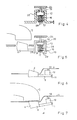
- Figure 1 shows a telephone set comprising a base 1 and a telephone handset 2 shown in the raised position and normally intended to come to rest in a cradle formed in the upper wall 4 of the base.
- a key 6 biased in the raised position by a spring, passes through an opening in this upper wall and is capable of being actuated by the weight of the handset. It is the structure and mounting of this key in relation to a line seizure switch which are the subject of the present invention and which will be described in more detail below.
- FIG 2 shows a partially sectioned side view corresponding to Figure 1, in which we can see laterally the cradle formed in the upper wall 4 of the base and the key 6 described above.
- This key 6 constitutes the lateral extension of a plate 8 intended to be mounted in the base so as to be able to pivot around an axis 10 defined by pins 11 following actuation of the key.
- On this part 8 are mounted a switch 12 with push button 13 and a return spring 15 resting on a rib 17 of the wall of the base of the telephone set.
- FIG. 3 represents a schematic embodiment of a device according to the invention assembled before mounting in the base of a telephone set.
- the key 6 is integral with a plate 8 provided at its longitudinal ends with pins 11 defining an axis of rotation 10 on the side of the plate 8 opposite the key 6 to allow pivoting of the assembly constituted by the key 6 and the plate 8.
- a structure 20 making it possible to maintain a push-button switch 12, the button 13 of which projects outwards from the device.
- the push-button can assume a depressed state, pressing against a part 21 of the upper wall 4, or come out when the key 6 is in a hurry.
- the structure 20 also makes it possible to contain a return spring 15.
- This spring bears against the lower face (opposite to the push button) of the switch 12 and thus ensures the blocking of the switch, and is intended, once mounted in the base, to rest on a rib of this base to ensure its return function.
- the structure 20 comprises flexible tongues 28 bent inward at their lower ends 29 allowing insertion of the switch and of the spring and ensuring blocking of these two parts once the spring is in place.
- the whole of the part illustrated in FIG. 3 is made of molded plastic, this plastic having sufficient flexibility to allow the spacing and tightening of the tongues 28.
- the part will have no is not the simplified form illustrated in Figure 3 but will be provided with various reinforcing ribs and notches allowing the possible passage of other parts.
- the device according to the invention assembled, it is put in place in the telephone set so that the pins 11 penetrate into housings forming bearings and that the spring 15 comes to bear on a rib 17 integral with the bottom wall of the telephone base.
- This rib is arranged to penetrate between the bent ends 29 of the tongues 28 and slightly compress the spring 15 which then no longer bears on these ends 29 which were used only for pre-assembly of the device according to the invention.
- FIGS. 6 and 7 will be understood from the previous explanations. They are intended to better show the movement of the push-button switch when the key 6 is free or pressed, respectively.
- a simple, flat and space-saving assembly makes it possible to directly actuate a line pick-up switch from the movement of a button receiving a telephone handset, the switch being directly mechanically secured to the button.
- This switch is of course provided with lugs and output wires intended to connect it to the electrical components, generally located on a printed circuit board, ensuring the various functions of the telephone set.
- the main function of this switch is a line seizure function, it is well known that this switch generally makes it possible to perform other auxiliary electrical functions and that it is therefore generally a multi-contact switch.
- An advantage of the present invention is to allow positioning of the printed circuits independently of the positioning of the handset button.
- the handset detector device is particularly simple since its elements can be pre-assembled before mounting in the base of a suitable telephone set.
Landscapes
- Engineering & Computer Science (AREA)
- Signal Processing (AREA)
- Telephone Set Structure (AREA)
Applications Claiming Priority (2)
| Application Number | Priority Date | Filing Date | Title |
|---|---|---|---|
| FR8914736 | 1989-11-03 | ||
| FR8914736A FR2654276A1 (fr) | 1989-11-03 | 1989-11-03 | Dispositif de detection du decrochement d'un combine telephonique. |
Publications (1)
| Publication Number | Publication Date |
|---|---|
| EP0426584A1 true EP0426584A1 (de) | 1991-05-08 |
Family
ID=9387252
Family Applications (1)
| Application Number | Title | Priority Date | Filing Date |
|---|---|---|---|
| EP90420472A Withdrawn EP0426584A1 (de) | 1989-11-03 | 1990-10-31 | Vorrichtung zum Erkennen des Abhebens eines Telefonhörers |
Country Status (5)
| Country | Link |
|---|---|
| US (1) | US5159628A (de) |
| EP (1) | EP0426584A1 (de) |
| JP (1) | JPH03169144A (de) |
| AU (1) | AU633988B2 (de) |
| FR (1) | FR2654276A1 (de) |
Cited By (1)
| Publication number | Priority date | Publication date | Assignee | Title |
|---|---|---|---|---|
| CN101466219B (zh) * | 2007-12-18 | 2011-12-14 | 鸿富锦精密工业(深圳)有限公司 | 滑盖结构及应用该滑盖结构的便携式电子装置 |
Citations (3)
| Publication number | Priority date | Publication date | Assignee | Title |
|---|---|---|---|---|
| GB2201063A (en) * | 1987-01-29 | 1988-08-17 | British Telecomm | Telephone switch hooks |
| GB2207324A (en) * | 1987-07-18 | 1989-01-25 | Stc Plc | Telephone hook switch |
| DE3838856A1 (de) * | 1987-02-01 | 1989-06-01 | Exicom Australia Pty Ltd | Gabelumschalter eines telefonapparates |
Family Cites Families (16)
| Publication number | Priority date | Publication date | Assignee | Title |
|---|---|---|---|---|
| JPS5338907A (en) * | 1976-09-22 | 1978-04-10 | Nippon Telegr & Teleph Corp <Ntt> | Hook-switch |
| US4188512A (en) * | 1978-11-22 | 1980-02-12 | Gte Automatic Electric Laboratories Incorporated | Telephone hookswitch actuator and handset support assembly |
| DE3128813A1 (de) * | 1981-07-21 | 1983-03-03 | Siemens AG, 1000 Berlin und 8000 München | Bedienungsorgan zum betaetigen von einrichtungen einer fernsprechstation |
| US4436964A (en) * | 1981-09-14 | 1984-03-13 | International Telephone And Telegraph Corporation | Hookswitch mechanism for telephone instrument |
| SU1040621A1 (ru) * | 1982-04-26 | 1983-09-07 | Предприятие П/Я В-2168 | Устройство дл управлени переключателем в телефонном аппарате |
| GB2126839B (en) * | 1982-09-09 | 1985-08-07 | Plessey Co Plc | Telephone apparatus |
| CA1199439A (en) * | 1983-11-22 | 1986-01-14 | Peter Conlon | Telephone hookswitch flasher |
| DE3342730A1 (de) * | 1983-11-25 | 1985-06-05 | Siemens AG, 1000 Berlin und 8000 München | Gabelumschalter fuer fernsprechgeraete |
| GB8401721D0 (en) * | 1984-01-23 | 1984-02-22 | British Telecomm | Switch operating mechanisms |
| GB2156181B (en) * | 1984-03-17 | 1987-05-07 | Standard Telephones Cables Ltd | Telephone hook switch |
| US4727573A (en) * | 1985-02-22 | 1988-02-23 | Hosiden Electronics Co., Ltd. | Switch with plural rotors |
| US4674120A (en) * | 1985-11-12 | 1987-06-16 | Northern Telecom Limited | Hook switch actuator assembly |
| JPS62241456A (ja) * | 1986-04-14 | 1987-10-22 | Matsushita Seiko Co Ltd | 電話機のフツクスイツチレバ−の取付装置 |
| JPH0345402Y2 (de) * | 1987-07-28 | 1991-09-25 | ||
| AU2566388A (en) * | 1987-11-18 | 1989-05-18 | Exicom Australia Pty Limited | A switch operating mechanism |
| JPH05338907A (ja) * | 1992-06-03 | 1993-12-21 | Mitsuba Seisakusho:Kk | 走行中の製品の印刷部検査方法とその装置 |
-
1989
- 1989-11-03 FR FR8914736A patent/FR2654276A1/fr not_active Withdrawn
-
1990
- 1990-10-15 AU AU64624/90A patent/AU633988B2/en not_active Ceased
- 1990-10-31 US US07/607,324 patent/US5159628A/en not_active Expired - Fee Related
- 1990-10-31 EP EP90420472A patent/EP0426584A1/de not_active Withdrawn
- 1990-11-01 JP JP2297042A patent/JPH03169144A/ja active Pending
Patent Citations (3)
| Publication number | Priority date | Publication date | Assignee | Title |
|---|---|---|---|---|
| GB2201063A (en) * | 1987-01-29 | 1988-08-17 | British Telecomm | Telephone switch hooks |
| DE3838856A1 (de) * | 1987-02-01 | 1989-06-01 | Exicom Australia Pty Ltd | Gabelumschalter eines telefonapparates |
| GB2207324A (en) * | 1987-07-18 | 1989-01-25 | Stc Plc | Telephone hook switch |
Non-Patent Citations (1)
| Title |
|---|
| PATENT ABSTRACTS OF JAPAN, vol. 2, no. 73 (E-037)[2798], 7 juin 1978; & JP-A-53 038 907 (NIPPON DENWA KOSHA) 10-04-1978 * |
Cited By (1)
| Publication number | Priority date | Publication date | Assignee | Title |
|---|---|---|---|---|
| CN101466219B (zh) * | 2007-12-18 | 2011-12-14 | 鸿富锦精密工业(深圳)有限公司 | 滑盖结构及应用该滑盖结构的便携式电子装置 |
Also Published As
| Publication number | Publication date |
|---|---|
| JPH03169144A (ja) | 1991-07-22 |
| US5159628A (en) | 1992-10-27 |
| AU633988B2 (en) | 1993-02-11 |
| AU6462490A (en) | 1991-05-09 |
| FR2654276A1 (fr) | 1991-05-10 |
Similar Documents
| Publication | Publication Date | Title |
|---|---|---|
| EP1193953A1 (de) | Elektronisches Gerät mit zusammenklappbarer Anzeigevorrichtung | |
| EP1245447A1 (de) | Vorrichtung mit abnehmbarer Gleitzentralkonsole | |
| FR2685553A1 (fr) | Element de connecteur coaxial coude apte a etre fixe a une carte imprimee. | |
| FR2762492A3 (fr) | Dispositif de fixation pour fixer un appareil a une ceinture | |
| FR2906641A1 (fr) | Dispositif d'eclairage interieur | |
| BE1014955A3 (fr) | Boitier pourvu de bornes de connexion. | |
| FR2675327A1 (fr) | Mecanisme de charniere pour radiotelephone repliable. | |
| WO2001053003A2 (fr) | Distributeur de produit fluide a organe de prehension | |
| EP3119241A1 (de) | Vorrichtung zur befestigung eines rahmens in einer durchgangsöffnung in einer platte | |
| FR2755790A1 (fr) | Commutateur a bouton-poussoir miniature, notamment pour une unite de disque souple | |
| EP0426584A1 (de) | Vorrichtung zum Erkennen des Abhebens eines Telefonhörers | |
| WO2013153456A1 (fr) | Accessoire pour appareil portable, pour l'application d'un film protecteur sur un écran de l'appareil | |
| FR2839393A1 (fr) | Agencement d'un element femelle et dispositif mobile. | |
| FR2553247A3 (fr) | Telephone, en particulier telephone pour automobile, equipe d'un dispositif de verrouillage perfectionne | |
| FR2783086A3 (fr) | Commutateur de touche pour clavier | |
| EP0251844B1 (de) | Klappgriff für eine Tür | |
| EP0119361B1 (de) | Einfassungsprofil für ein schwenkbares Verbundfenster | |
| EP3489980B1 (de) | Betätigungsvorrichtung vom typ druckknopf mit flachem aufbau | |
| FR2759871A1 (fr) | Etui pour telephone portable | |
| FR2458242A1 (fr) | Ferrure formant boucle de ceinture de securite | |
| FR2661274A1 (fr) | Dispositif de visualisation d'appareil d'enregistrement et de reproduction. | |
| FR2505099A1 (fr) | Cosse femelle de contact electrique | |
| BE1014511A6 (fr) | Dispositif de commutation. | |
| EP1274152B1 (de) | Schwimmender Batterieverbinder | |
| EP0421898B1 (de) | Fernsprechhandapparat |
Legal Events
| Date | Code | Title | Description |
|---|---|---|---|
| PUAI | Public reference made under article 153(3) epc to a published international application that has entered the european phase |
Free format text: ORIGINAL CODE: 0009012 |
|
| AK | Designated contracting states |
Kind code of ref document: A1 Designated state(s): CH DE ES FR GB IT LI SE |
|
| 17P | Request for examination filed |
Effective date: 19911010 |
|
| RAP1 | Party data changed (applicant data changed or rights of an application transferred) |
Owner name: CROUZET AUTOMATISMES |
|
| 17Q | First examination report despatched |
Effective date: 19940309 |
|
| STAA | Information on the status of an ep patent application or granted ep patent |
Free format text: STATUS: THE APPLICATION IS DEEMED TO BE WITHDRAWN |
|
| 18D | Application deemed to be withdrawn |
Effective date: 19941201 |