EP0426607A2 - Dispositif de transfert - Google Patents
Dispositif de transfert Download PDFInfo
- Publication number
- EP0426607A2 EP0426607A2 EP90630180A EP90630180A EP0426607A2 EP 0426607 A2 EP0426607 A2 EP 0426607A2 EP 90630180 A EP90630180 A EP 90630180A EP 90630180 A EP90630180 A EP 90630180A EP 0426607 A2 EP0426607 A2 EP 0426607A2
- Authority
- EP
- European Patent Office
- Prior art keywords
- felt
- dryer
- web
- upstream
- roll
- Prior art date
- Legal status (The legal status is an assumption and is not a legal conclusion. Google has not performed a legal analysis and makes no representation as to the accuracy of the status listed.)
- Granted
Links
Images


Classifications
-
- D—TEXTILES; PAPER
- D21—PAPER-MAKING; PRODUCTION OF CELLULOSE
- D21F—PAPER-MAKING MACHINES; METHODS OF PRODUCING PAPER THEREON
- D21F5/00—Dryer section of machines for making continuous webs of paper
- D21F5/02—Drying on cylinders
- D21F5/04—Drying on cylinders on two or more drying cylinders
-
- D—TEXTILES; PAPER
- D21—PAPER-MAKING; PRODUCTION OF CELLULOSE
- D21F—PAPER-MAKING MACHINES; METHODS OF PRODUCING PAPER THEREON
- D21F5/00—Dryer section of machines for making continuous webs of paper
- D21F5/02—Drying on cylinders
- D21F5/04—Drying on cylinders on two or more drying cylinders
- D21F5/042—Drying on cylinders on two or more drying cylinders in combination with suction or blowing devices
-
- D—TEXTILES; PAPER
- D21—PAPER-MAKING; PRODUCTION OF CELLULOSE
- D21G—CALENDERS; ACCESSORIES FOR PAPER-MAKING MACHINES
- D21G9/00—Other accessories for paper-making machines
- D21G9/0063—Devices for threading a web tail through a paper-making machine
Definitions
- the present invention relates to a transfer apparatus for transferring a web from an upstream dryer to a downstream dryer of a dryer section. More particularly, the present invention relates to a transfer apparatus for transferring a web without open draw between a first and a second felt of a dryer section.
- TOTAL BELRUN Co-pending U.S. patent application serial number 07/014,569 to Beloit Corporation discloses a TOTAL BELRUN dryer section in which a web is guided from a press section to a calender through a dryer section wherein opposite sides of the web are alternately dried as the web moves without open draw between successive tiers of dryers.
- TOTAL BELRUN is a registered trademark of Beloit Corporation.
- a web is dried by passing the web in sinusoidal configuration past a plurality of dryer drums such that a top felt presses the web into close conformity with an upper tier of dryers and a bottom felt presses the web into conformity with the heated external surface of a lower tier of dryers.
- a dryer arrangement requires the web to progressively move between the dryers of the respective upper and lower tiers in open draw. Accordingly, movement of the web in such open draws causes edge flutter, curl and cockling of the resultant web.
- the so-called serpentine run dryer section was developed in which the web was supported throughout a dryer section by a single dryer felt moving in sinusoidal configuration around the dryer drums of the upper and lower tiers.
- the serpentine configuration helped to alleviate the problem of edge flutter, a further problem was introduced in that the lower dryer drums became redundant because the dryer felt disposed between the web and the lower dryer drums acted as an insulator and prevented drying of the web during passage around the lower dryer drums.
- the web and dryer felt move contiguously around alternately a dryer drum and a vacuum transfer guide roll.
- the arrangement is such that the web is held in close conformity with the dryer felt during passage of the web around the vacuum transfer roll.
- the web is sandwiched between the dryer felt and the dryer drum during passage of the web around the dryer for drying thereof.
- the web is transferred without open draw between successive tiers of dryers so that as the web moves between successive tiers, opposite sides of the web are dried. Accordingly, as the web progresses from the press section to the calender, opposites sides of the web are alternately dried and the web is restrained against cross-machine shrinkage thereof. Therefore, edge flutter, curl and cockling of the web are inhibited.
- the present invention is an improvement over the arrangement disclosed in U.S. serial number 07/014,569 and relates particularly to the transfer arrangement between successive tiers.
- serial number 07/014,569 an upstream and a downstream vacuum roll guide the respective dryer felts such that the dryer felts define therebetween a web transfer section.
- vacuum transfer rolls are relatively costly, and the present invention seeks to provide a transfer apparatus without open draw of the web using plain transfer rolls in association with adjacent web transfer boxes.
- Another object of the present invention is the provision of a transfer apparatus which includes a first felt roll and a second felt roll disposed between an upstream dryer and the first felt roll such that the web is disposed between the second felt roll and the first felt.
- a second dryer felt passes around the second felt roll and extends from the second felt roll to and around a downstream dryer such that the first and the second felts defines therebetween a web transfer section, the web being sandwiched between the first and the second felts between the second and the first felt rolls.
- Another object of the present invention is the provision of a transfer apparatus which includes means for positively transferring the web from the first to the second felt when the first felt diverges relative to the second felt.
- Another object of the present invention is the provision of a transfer apparatus in which a first and second felt roll and an upstream and downstream dryer are disposed relative to each other such that the web between the upstream and downstream dryers follows a common tangent to the dryers and felt rolls.
- Another object of the present invention is the provision of a transfer apparatus in which the first and the second felt rolls intersect a common tangent of the upstream and downstream dryers such that the first felt wraps around the second felt roll and the second felt wraps around the first felt roll so that the felts extending between the second and first felts rolls are disposed parallel relative to each other for stabilizing the felts during transit through the transfer section.
- Another object of the present invention is the provision of a transfer apparatus in which the felts define therebetween a converging nip such that when the second felt is driven at a higher speed relative to the first felt, tension within the web during transfer between the first and the second felts is maintained.
- Another object of the present invention is the provision of a transfer apparatus which includes a blow box disposed between the first felt roll and the downstream dryer for generating an upstream flow of air for drawing the web into close conformity with the second felt when the first felt diverges relative to the second felt.
- the blow box also prevents air from entering between an upstream orifice of the blow box and the first felt roll in a direction from the second felt roll which would otherwise tend to cause a tail of the web to follow the first felt.
- Another object of the present invention is the provision of a transfer apparatus which includes a blow box having a downstream orifice such that during threading of the dryer section, a tail of the web is positively held in close conformity with the second felt until the tail is disposed between the downstream dryer and the second felt.
- Another object of the present invention is the provision of a transfer apparatus including a blow box having openings along the edges thereof so that during use of the apparatus, air flows through the openings for drawing the first and the second edges respectively into close conformity with the second felt so that edge flutter of the web relative to the second felt is inhibited.
- Another object of the present invention is the provision of a transfer apparatus including a vacuum box for drawing the web into close conformity with the second felt when the first felt diverges relative to the second felt and for preventing air from entering between an upstream slot and the first felt roll in a direction from the second felt roll.
- Another object of the present invention is the provision of a transfer apparatus which includes a plenum for generating a current of air such that the web is drawn into close conformity with the first felt when the first felt diverges relative to the upstream dryer and for diverting a boundary layer of air that follows the upstream dryer.
- Another object of the present invention is the provision of a transfer apparatus which includes a plenum for directing a current of air such that during threading of the dryer section, a tail of the web is positively urged into close conformity with the first felt until the tail is sandwiched between the felts during passage through the web transfer section.
- Another object of the present invention is the provision of a transfer apparatus in which the transfer means defines a wall which diverges in a direction from the first felt roll towards the downstream dryer so that during movement of the second felt between the first felt roll and the downstream dryer, a vacuum is generated between the wall and the second felt for drawing the web into close conformity with the second felt.
- Another object of the present invention is the provision of a transfer apparatus in which the plenum includes a surface which is disposed on the opposite side of the first felt relative to the second felt roll for generating a partial vacuum between the surface and the first felt for urging the web into close conformity with the first felt between the upstream dryer and the second felt roll.
- the present invention relates to an apparatus and method for transferring a web from an upstream dryer to a downstream dryer of a dryer section.
- the apparatus includes a first dryer felt which extends around the upstream dryer for supporting the web such that the web is disposed between the first felt and the upstream dryer for drying a first side of the web.
- a first felt roll is disposed downstream relative to the upstream dryer for guiding the first felt such that the first felt diverges relative to the upstream dryer and extends from the upstream dryer to and around the first felt roll.
- a second felt roll is disposed between the upstream dryer and the first felt roll such that the web is disposed between the second felt roll and the first felt.
- a second dryer felt extends around the downstream dryer for supporting the web such that the web is disposed between the second dryer felt and the downstream dryer for drying a second side of the web.
- the second felt passes around the second felt roll and extends from the second felt roll to and around the downstream dryer such that the first and second felts define therebetween a web transfer section.
- the arrangement is such that the web is sandwiched between the first and the second felts between the second and first felt rolls.
- a transfer means positively transfers the web from the first felt to the second felt when the first felt diverges relative to the second felt.
- first and the second felt rolls and the upstream and downstream dryers are disposed relative to each other such that the web between the upstream and downstream dryers follows a common tangent to the dryers and felt rolls.
- the first and the second felt rolls intersect a common tangent of the upstream and downstream dryers such that the first felt wraps around a portion of the second felt roll and the second felt wraps around a portion of the first felt roll so that the felts extending between the second and first felt rolls are disposed parallel relative to each other for stabilizing the felt during transit through the transfer section.
- the second felt roll is spaced relative to a common tangent of the upstream and downstream dryers and the first felt roll intersects the tangent such that the felts define therebetween a converging nip such that when the second felt is driven at a higher speed than the first felt, tension within the web during transfer between the first and the second felts is maintained.
- the felt rolls are spaced relative to a common tangent of the upstream and downstream dryers such that a gap is defined between the felts permitting the second felt to be moved at a higher speed relative to the speed of the first felt, thereby permitting transfer of the web from the first to the second felt while maintaining the web under tension.
- the transfer means includes a blow box disposed between the first felt roll and the downstream dryer, the blow box being disposed on the opposite side of the second felt relative to the first felt roll such that the second felt is disposed between the web and the blow box.
- blow box defines a cross-machine directional upstream orifice for generating an upstream flow of air for drawing the web into close conformity with the second felt when the first felt diverges relative to the second felt.
- blow box defines a cross-machine directional downstream orifice which is disposed adjacent to and on the opposite side of the second felt relative to an in-going nip defined between the second felt and the downstream dryer such that during threading of the dryer section, a tail of the web is positively held in close conformity with the second felt until the tail is disposed between the downstream dryer and the second felt.
- the blow box defines a first and second opening which extend between the first felt roll and the downstream dryer.
- the first and second openings are disposed respectively adjacent to the edges of the web so that during use of the apparatus, air flows through the first and second openings for drawing the first and second edges respectively into close conformity with the second felt so that edge flutter of the web relative to the second felt is inhibited.
- the transfer means includes a vacuum box which is disposed between the first felt roll and the downstream dryer.
- the vacuum box defines an upstream slot which extends in a cross-machine direction for drawing the web into close conformity with the second felt when the first felt diverges relative to the second felt and for preventing air from entering between the upstream slot and the first felt roll in a direction from the second felt roll.
- the transfer apparatus also includes further means disposed between the upstream dryer and the second felt roll for urging the web away from the upstream dryer and into close conformity with the first dryer felt between the upstream dryer and the second felt roll.
- the further means includes a plenum which defines a cross-machine directional upstream nozzle disposed adjacent to and on the opposite side of the first felt relative to a divergent nip defined between the upstream dryer and the first felt.
- the upstream nozzle generates a current of air such that the web is drawn into close conformity with the first felt when the first felt diverges relative to the upstream dryer. Furthermore, the current of air diverts a boundary layer of air which follows the upstream dryer.
- the plenum further includes a cross-machine directional downstream nozzle which is disposed adjacent to and on the opposite side of the first felt relative to a convergent nip defined between the second felt roll and the first felt.
- the downstream nozzle directs a current of air such that during threading of the dryer section, a tail of the web is positively urged into close conformity with the first felt until the tail is sandwiched between the felts during passage through the web transfer section.
- the transfer means also defines a wall which diverges in a direction from the first felt roll towards the downstream dryer so that during movement of the second felt between the first felt roll and the downstream dryer, a partial vacuum is generated between the wall and the second felt for drawing the web into close confcrmity with the second felt.
- the further means also includes a surface which is disposed on the opposite side of the first felt relative to the second felt.
- the surface extends between the upstream dryer and the second felt roll. The surface diverges from the first felt in a direction from the upstream dryer towards the second felt roll for generating a partial vacuum between the surface and the first felt for urging the web into close conformity with the first felt between the upstream dryer and the second felt roll.
- the present invention also includes a method for transferring a web from an upstream dryer to a downstream dryer of a dryer section, the method comprising the steps of: extending a first dryer felt around the upstream dryer for supporting the web such that the web is disposed between the first felt and the upstream dryer for drying a first side of the web; guiding the first felt around a first felt roll disposed downstream relative to the upstream dryer such that the first felt diverges relative to the upstream dryer and extends from the upstream dryer to and around the first felt roll; supporting the web such that the web is disposed between a second felt and the downstream dryer for drying a second side of the web; guiding the second felt around a second felt roll disposed between the upstream dryer and the first felt roll such that the web is disposed between the second felt roll and the first felt; passing the second felt around the second felt roll so that the second felt extends from the second felt roll to and around the downstream dryer such that the first and second felts defines therebetween a web transfer section, the web being sandwiched between the first and second felt
- Such modifications would be the provision of means for positively transferring the web from the first to the second felt when the first felt diverges relative to the second felt.
- Such means could include merely a diverging wall for generating, in use of the apparatus, sufficient vacuum to cause a tail of the web to follow the second felt rather than following the first felt.
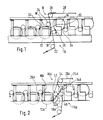
- FIG. 1 is a side-elevational view of a TOTAL BELRUN transfer apparatus as described in co-pending U.S. serial number 07/014,569.
- the transfer apparatus generally designated 10 transfers a web W from an upstream dryer 12 to a downstream dryer 14 of a dryer section generally designated 16.
- the apparatus 10 includes a first dryer felt 18 extending around the upstream dryer 12 for supporting the web W such that the web W is disposed between the first felt 18 and the upstream dryer 12 for drying a first side 20 of the web W.
- a first felt roll 22 is disposed downstream relative to a transfer vacuum roll 24 such that the first felt 18 is guided from the dryer 12 around the vacuum transfer roll 24 to and around the felt roll 22.
- a second felt roll 26 guides a second felt 28 towards and around a further transfer vacuum guide roll 30 such that a web transfer section 32 is defined between the felts 18 and 28.
- the first side 20 of the web W is dried during passage of the web W past the upstream dryer 12, and a second side 34 of the web W is dried during passage of the web past the downstream dryer 14.
- the web W is transferred through the web transfer section 32 without open draw, thereby restraining the web W against cross-machine directional shrinkage thereof.
- the aforementioned arrangement requires the provision of a first and second relatively costly vacuum transfer roll 24 and 30 respectively.
- the web W follows a path other than unidirectional during passage of the web through the transfer apparatus 10.
- the present invention overcomes the need for the two vacuum transfer rolls 24 and 30 shown in Figure 1 and provides a unidirectional transfer of the web through a transfer apparatus.
- Figure 2 is a side-elevational view of a transfer apparatus generally designated 10A according to the present invention.
- the apparatus 10A transfers a web WA from an upstream dryer 12A to a downstream dryer 14A of a dryer section generally designated 16A.
- the apparatus 10A includes a first dryer felt 18A which extends around the upstream dryer 12A for supporting the web WA such that the web WA is disposed between the first felt 18A and the upstream dryer 12A for drying a first side 20A of the web WA.
- a first felt roll 40 is disposed downstream relative to the upstream dryer 12A for guiding the first felt 18A such that the first felt 18A diverges relative to the upstream dryer 12A and extends from the upstream dryer 12A to and around the first felt roll 40.
- a second felt roll 42 is disposed between the upstream dryer 12A and the first felt roll 40 such that the web WA is disposed between the second felt roll 42 and the first felt 18A.
- a second dryer felt 28A extends around the downstream dryer 14A for supporting the web WA such that the web WA is disposed between the second dryer felt 28A and the downstream dryer 14A for drying a second side 34A of the web WA.
- the second felt 28A passes around the second felt roll 42 and extends from the second felt roll 42 to and around the downstream dryer 14A such that the first and second felts 18A and 28A respectively define therebetween a web transfer section 32A.
- the web WA is therefore sandwiched between the first and second felts 18A and 28A respectively between the second and first felt rolls 42 and 40 respectively.
- Means generally designated 44 are provided for positively transferring the web WA from the first felt 18A to the second felt 28A when the first felt 18A diverges relative to the second felt 28A.
- Figure 3 is an enlarged side-elevational view of the transfer apparatus 10A shown in Figure 2 and shows the first and second felt rolls 40 and 42 respectively. Also, the upstream and downstream dryers 12A and 14A respectively are disposed relative to each other such that the web WA between the upstream and downstream dryers 12A and 14A follow a common tangent T to the dryers 12A and 14A and the felt rolls 40 and 42 respectively.
- Figure 4 is a similar view to that shown in Figure 3 but shows an alternative embodiment of the present invention in which a first and a second felt roll 40B and 42B respectively intersect a common tangent TB of an upstream and a downstream dryer 12B and 14B respectively such that a first felt 18B wraps around the second felt roll 42B and a second felt 28B wraps around the first felt roll 40B so that the felts 18B and 28B extend between the second and first felt rolls 42B and 40B respectively to define a web transfer section 32B.
- the felts 18B and 28B are disposed parallel relative to each other during passage through the transfer section 32B for stabilizing the felts 18B and 28B during transit through the transfer section 32B.
- Figure 5 is a similar view to that shown in Figure 3 but shows a further embodiment of the present invention in which a second felt roll 42C is spaced relative to a common tangent TC of an upstream and a downstream dryer 12C and 14C.
- a first felt roll 40C intersects the tangent TC such that a first and second felt 18C and 28C define therebetween a converging nip 46.
- the arrangement is such that when the second felt 28C is driven at a higher speed than the first felt 18C, tension within the web WC during transfer between the first and second felts 18C and 28C is maintained.
- FIG 6 is a similar view to that shown in Figure 3 but shows yet another embodiment of the present invention in which a transfer apparatus 10D includes a first and second felt roll 40D and 42D respectively.
- the felt rolls 40D and 42D are spaced relative to a common tangent TD of an upstream and a downstream dryer 12D and 14D such that a gap, as indicated by the arrow G, is defined between a first and second felt 18D and 28D.
- Such gap G permits the second felt 28D to be moved at a higher speed relative to the speed of the first felt 18D, thereby permitting transfer of a web WD from the first felt 18D to the second felt 28D while maintaining the web WD under tension.
- the means generally designated 44 includes a blow box 48 disposed between the first felt roll 40 and the downstream dryer 14A.
- the blow box 48 is disposed on the opposite side of the second felt 28A relative to the first felt roll 40 such that the second felt 28A is disposed between the web WA and the blow box 48.
- the blow box 48 defines a cross-machine directional upstream orifice 50 for generating an upstream flow of air, as indicated by the arrow 52, for drawing the web WA into close conformity with the second felt 28A when the first felt 18A diverges relative to the second felt 28A.
- the flow of air 52 also prevents air from entering between the upstream orifice 50 and the first felt roll 40 in a direction from the second felt roll 42.
- the blow box 48 defines a cross-machine directional downstream orifice 54 which is disposed adjacent to and on the opposite side of the second felt 28A relative to an in-going nip 56 defined between the second felt 28A and the downstream dryer 14A.
- the arrangement is such that during threading of the dryer section 16A, a tail of the web WA is positively held in close conformity with the second felt 28A until the tail is disposed between the downstream dryer 14A and the second felt 28A.
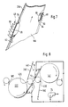
- Figure 7 is a fragmentary perspective view of the blow box 48 as shown in Figure 3 and shows the blow box 48 defining a first and second opening 58 and 60 which extend between the first felt roll 40 and the downstream dryer 14A.
- the felt roll 40 and the dryer 14A are not shown in Figure 7 for clarity.
- the first and second openings 58 and 60 are disposed respectively adjacent to the edges 62 and 64 of the web WA so that during use of the apparatus 10A, air flows, as indicated by the arrows 66 and 68, through the first and second openings 58 and 60 for drawing the first and second edges 62 and 64 respectively into close conformity with the second felt 28A so that edge flutter of the web WA relative to the second felt 28A is inhibited.
- the means 44E includes a vacuum box 70 which is disposed between a first felt roll 40E and a downstream dryer 14E.
- the vacuum box 70 defines an upstream slot 72 which extends in a cross-machine direction such that when the vacuum box 70 is connected to a source of partial vacuum 74, a web WE is drawn into close conformity with a second felt 28E when a first felt 18E diverges relative to the second felt 28E.
- the transfer apparatus 10A also includes further means generally designated 80.
- the further means 80 is disposed between the upstream dryer 12A and the second felt roll 42 for urging the web WA away from the upstream dryer 12A and into close conformity with the first dryer felt 18A between the upstream dryer 12A and the second felt roll 42.
- the further means 80 includes a plenum 82 defining a cross-machine directional upstream nozzle 84 disposed adjacent to and on the opposite side of the first felt 18A relative to a divergent nip 86 defined between the upstream dryer 12A and the first felt 18A.
- the upstream nozzle 84 generates a current of air indicated by the arrow 88 such that the web WA is drawn into close conformity with the first felt 18A when the first felt 18A diverges relative to the upstream dryer 12A.
- the current of air 88 also diverts a boundary layer of air, as indicated by the arrow 90, which follows the upstream dryer 12A.
- the plenum 82 further includes a cross-machine directional downstream nozzle 92 disposed adjacent to and on the opposite side of the first felt 18A relative to a convergent nip 94 defined between the second felt roll 42 and the first felt 18A.
- the downstream nozzle 92 directs a current of air, indicated by the arrow 96, such that during threading of the dryer section 16A, a tail of the web WA is positively urged into close conformity with the first felt 18A until the tail is sandwiched between the felts 18A and 28A during passage through the web transfer section 32A.
- the means 44 defines a wall 100 which diverges in a direction, as indicated by the arrow 102, from the first felt roll 40 towards the downstream dryer 14A so that during movement of the second felt 28A between the first felt roll 40 and the downstream dryer 14A, a vacuum is generated between the wall 100 and the second felt 28A for drawing the web WA into close conformity with the second felt 28A.
- the further means 80 includes a surface 110 disposed on the opposite side of the first felt 18A relative to the second felt roll 42.
- the surface 110 extends between the upstream dryer 12A and the second felt roll 42.
- the surface 110 diverges from the first felt 18A in a direction, as indicated by the arrow 102, from the upstream dryer 12A towards the second felt roll 42 for generating a partial vacuum between the surface 110 and the first felt 18A for urging the web WA into close conformity with the first felt 18A between the upstream dryer 12A and the second felt roll 42.
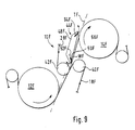
- Figure 9 is a side-elevational view of yet another embodiment of the present invention and includes a transfer apparatus generally designated 10F.
- the apparatus 10F includes a first and second felt roll 40F and 42F respectively.
- the felt roll 40F is spaced relative to a common tangent TF of an upstream and downstream dryer 12F and 14F respectively.
- the second felt roll 42F intersects the common tangent TF so that a first felt 18F extending around dryer 12F extends around a portion of the roll 40F so that the web WF is sandwiched between the first felt 18F and a second felt 28F extending around felt roll 42F and the dryer 14F.
- means generally designated 44F includes a blow box 48F disposed between the first felt roll 40F and the downstream dryer 14F.
- the blow box 48F is disposed on the opposite side of the second felt 28F relative to the first felt roll 40F such that the second felt 28F is disposed between the web WF and the blow box 48F.
- the blow box 48F defines a cross-machine directional upstream orifice 50F for generating an upstream flow of air as indicated by the arrow 52F for drawing the web WF into close conformity with the second felt 28F when the first felt 18F diverges relative to the second felt 28F.
- the flow of air 52F also prevents air from entering between the upstream orifice 50F and the first felt roll 40F in a direction from the second felt roll 42F which would tend to detach a tail of the web from the second felt 28F.
- the blow box 48F defines a cross-machine directional downstream orifice 54F which is disposed adjacent to and on the opposite side of the second felt 28F relative to an in-going nip 56F defined between the second felt 28F and the downstream dryer 14F.
- the arrangement is such that during threading of the dryer section, a tail of the web WF is positively held in close conformity with the second felt 28F from the second felt roll 42F until the tail is disposed between the downstream dryer 14F and the second felt 28F.
- a vacuum box can be used in place of the blow box 48F and a vacuum or blow box similar to the means 80 shown in Figure 3 can be disposed between the dryer 12F and the second felt roll 42F.
- air is supplied to the blow box 48 and to the plenum 82 so that when the transfer apparatus is to be threaded, a tail of the web WA is drawn towards felt 18A as felt 18A diverges relative to the upstream dryer 12A.
- the tail automatically threads through converging nip 94 because the positive pressure at converging nip 94 is reduced by the flow of air 96.
- the tail progresses through the web transfer section 32A and follows the second felt 28A rather than the first felt 18A due to the air current 52 which draws the tail towards the second felt 28A.
- the positive air pressure nip 56 is compensated for by the provision of the orifice 54 so that the tail readily threads between the second felt 28A and the downstream dryer 14A.
- the diverging surface 110 and the diverging wall 100 augment the flows of air generated by the plenum and blow box respectively.
- the arrangement shown in Figure 4 is similar in operation to that shown in Figure 3 except in that the web transfer section 32B enables a more positive stabilization of the respective dryer felts.
- Figure 5 provides an in-going nip 46 between the felts 18C and 28C so that when the felt 28C moves at a slightly higher speed than the felt 18C, the web WC is maintained in tension.
- Figure 6 shows a gap G between the felts 18D and 28D.
- gap G is very small in practice but is shown in Figure 6 as a relatively large gap for clarity.
- the web WD is positively transferred from the felt 18D due to an upstream flow of air from the adjacent blow box so that the web WD is positively drawn towards the felt 28D when the felt 18D diverges relative to the second felt 28D.
- the openings 58 and 60 generate air flows which draw the edges 62 and 64 of the web into close conformity with the supporting felt 28A.
- blow box and plenum are replaced by vacuum boxes for positively drawing the tail of the web into conformity with the first felt 18E and then towards the second felt 28E when the first felt diverges relative to the second felt 28E.
- the present invention provides a transfer apparatus that does not require relatively costly vacuum transfer rolls. Furthermore, the present invention provides a unidirectional transfer of the web from an upstream to a downstream dryer for drying alternate sides of the web.
Landscapes
- Paper (AREA)
- Drying Of Solid Materials (AREA)
- Treatment Of Fiber Materials (AREA)
Applications Claiming Priority (2)
| Application Number | Priority Date | Filing Date | Title |
|---|---|---|---|
| US431961 | 1989-11-03 | ||
| US07/431,961 US5101577A (en) | 1987-02-13 | 1989-11-03 | Web transfer apparatus |
Publications (3)
| Publication Number | Publication Date |
|---|---|
| EP0426607A2 true EP0426607A2 (fr) | 1991-05-08 |
| EP0426607A3 EP0426607A3 (fr) | 1991-07-10 |
| EP0426607B1 EP0426607B1 (fr) | 1995-04-19 |
Family
ID=23714180
Family Applications (1)
| Application Number | Title | Priority Date | Filing Date |
|---|---|---|---|
| EP90630180A Expired - Lifetime EP0426607B1 (fr) | 1989-11-03 | 1990-10-11 | Dispositif de transfert |
Country Status (12)
| Country | Link |
|---|---|
| US (1) | US5101577A (fr) |
| EP (1) | EP0426607B1 (fr) |
| JP (1) | JPH0756118B2 (fr) |
| KR (1) | KR0163581B1 (fr) |
| CN (1) | CN1021981C (fr) |
| AU (1) | AU637833B2 (fr) |
| BR (1) | BR9005121A (fr) |
| CA (1) | CA2029252C (fr) |
| DE (1) | DE69018771T2 (fr) |
| FI (1) | FI905028A7 (fr) |
| MX (1) | MX173676B (fr) |
| PL (1) | PL166274B1 (fr) |
Cited By (12)
| Publication number | Priority date | Publication date | Assignee | Title |
|---|---|---|---|---|
| WO1992008004A1 (fr) * | 1990-10-31 | 1992-05-14 | Beloit Corporation | Appareil de sechage |
| DE4124648A1 (de) * | 1991-07-25 | 1993-01-28 | Escher Wyss Gmbh | Einrichtung zur verbindung zweier trockengruppen einer papiermaschine |
| DE4311351A1 (fr) * | 1992-04-13 | 1993-09-02 | Voith Gmbh J M | |
| WO1993022497A1 (fr) * | 1992-04-24 | 1993-11-11 | Beloit Technologies, Inc. | Section de sechage a etage unique pour empecher le gondolage |
| US5388347A (en) * | 1992-12-30 | 1995-02-14 | Valmet Paper Machinery, Inc. | Dryer section in a paper machine |
| US5438765A (en) * | 1991-11-05 | 1995-08-08 | Valmet Paper Machinery Inc. | Method and apparatus for eliminating the flutter of a paper web in the dryer section of a papermaking machine between two single felt configurations therein |
| US5503716A (en) * | 1992-03-05 | 1996-04-02 | Valmet Paper Machinery, Inc. | Device for guiding a leader of a web in a paper machine |
| US5542193A (en) * | 1992-04-24 | 1996-08-06 | Beloit Technologies, Inc. | Dryer group for curl control |
| DE19601589A1 (de) * | 1996-01-18 | 1997-07-24 | Voith Sulzer Papiermasch Gmbh | Vorrichtung zur Verbindung zweier Trockengruppen |
| US5884415A (en) * | 1992-04-24 | 1999-03-23 | Beloit Technologies, Inc. | Paper making machine providing curl control |
| DE19959669A1 (de) * | 1999-12-10 | 2001-06-13 | Voith Paper Patent Gmbh | Trockenpartie |
| EP2057315A4 (fr) * | 2006-08-25 | 2014-01-08 | Runtech Systems Oy | Procédé et dispositif destiné à guider un papier en bobines ou similaire |
Families Citing this family (18)
| Publication number | Priority date | Publication date | Assignee | Title |
|---|---|---|---|---|
| US5404653A (en) | 1987-02-13 | 1995-04-11 | Beloit Technologies, Inc. | Apparatus for drying a web |
| US6049999A (en) | 1987-02-13 | 2000-04-18 | Beloit Technologies, Inc. | Machine and process for the restrained drying of a paper web |
| US5507104A (en) | 1987-02-13 | 1996-04-16 | Beloit Technologies, Inc. | Web drying apparatus |
| DE9100762U1 (de) * | 1991-01-24 | 1991-04-11 | J.M. Voith Gmbh, 7920 Heidenheim | Trockenpartie |
| DE9110134U1 (de) * | 1991-08-16 | 1991-09-26 | J.M. Voith Gmbh, 7920 Heidenheim | Anordnung zum Überführen einer laufenden Bahn |
| DE4244884C2 (de) * | 1992-06-05 | 2001-11-29 | Voith Paper Patent Gmbh | Maschine zur Herstellung einer Faserstoffbahn |
| CA2118307C (fr) * | 1993-02-19 | 1997-03-25 | Pekka Eskelinen | Methode et dispositif pour assurer le passage de la bande dans le sechoir a tambours multiples d'une machine a papier |
| US5600897A (en) * | 1993-08-06 | 1997-02-11 | J.M. Voith Gmbh | Mixed dryer section including single-tier and double-tier drying groups with automatic ropeless threading |
| EP0726355B1 (fr) * | 1995-02-09 | 2002-06-05 | Voith Paper Patent GmbH | Procédé de transfert d'une bande en papier d'une première à une deuxième station de traitement d'une machine à papier |
| US5557863A (en) * | 1995-04-12 | 1996-09-24 | Valmet Corporation | Blow device for a dryer section of a paper machine |
| US5678321A (en) * | 1995-09-12 | 1997-10-21 | Beloit Technologies, Inc. | Air caps for two tier double felted dryer |
| US5600898A (en) * | 1995-09-12 | 1997-02-11 | Beloit Technologies, Inc. | Curl control by dryer aircaps in top felted dryer section |
| EP0902122B1 (fr) * | 1997-07-22 | 2004-11-24 | Voith Paper Patent GmbH | Séchage en support total |
| AT413709B (de) * | 2004-06-28 | 2006-05-15 | Andritz Ag Maschf | Vorrichtung zum kontinuierlichen trocknen einer faserstoffbahn |
| US20100213305A1 (en) * | 2009-02-26 | 2010-08-26 | Andritz Inc. | Apparatus and method for stabilizing a moving web |
| CN102666982B (zh) * | 2009-12-22 | 2016-03-09 | 梅特索纸业有限公司 | 排气模块、供气模块、输送纤维纸幅的系统、干端及方法 |
| DE102015001008A1 (de) * | 2015-01-28 | 2016-07-28 | Andritz Küsters Gmbh | Verfahren und Vorrichtung zur Herstellung von nassgelegten Vliesstoffen |
| DE102020119892A1 (de) * | 2020-07-28 | 2022-02-03 | Voith Patent Gmbh | Maschine und Verfahren zur Herstellung einer Faserstoffbahn |
Family Cites Families (12)
| Publication number | Priority date | Publication date | Assignee | Title |
|---|---|---|---|---|
| US3250019A (en) * | 1962-09-10 | 1966-05-10 | Edward D Beachler | Dryer felt |
| DE2212209C3 (de) * | 1972-03-14 | 1980-05-29 | Escher Wyss Gmbh, 7980 Ravensburg | Trockenpartie |
| FI53333C (fi) * | 1972-11-13 | 1978-04-10 | Valmet Oy | Torkningscylindergrupp i en flercylindertork foer en materialbana i synnerhet foer papper |
| US3874997A (en) * | 1973-03-21 | 1975-04-01 | Valmet Oy | Multiple cylinder drier in a paper machine |
| US4359827B1 (en) * | 1979-11-05 | 1994-03-29 | Keith V Thomas | High speed paper drying |
| CA1250744A (fr) * | 1984-12-20 | 1989-03-07 | Ralph J. Futcher | Feutre de sechoir |
| JPS61217673A (ja) * | 1985-03-22 | 1986-09-27 | 山陽国策パルプ株式会社 | 多筒式乾燥装置 |
| FI76142C (fi) * | 1985-11-14 | 1988-09-09 | Valmet Oy | Fickventilationsfoerfarande och -anordning i en pappersmaskins maongcylindertork. |
| US4698919A (en) * | 1986-04-08 | 1987-10-13 | Beloit Corp. | Apparatus for assisting the transfer of a web to a drying section |
| JPS6389996U (fr) * | 1986-12-02 | 1988-06-10 | ||
| US4934067A (en) * | 1987-02-13 | 1990-06-19 | Beloit Corporation | Apparatus for drying a web |
| US4891891A (en) * | 1988-10-11 | 1990-01-09 | Beloit Corporation | Dryer section apparatus and method |
-
1989
- 1989-11-03 US US07/431,961 patent/US5101577A/en not_active Expired - Fee Related
-
1990
- 1990-10-06 CN CN90108274A patent/CN1021981C/zh not_active Expired - Fee Related
- 1990-10-11 DE DE69018771T patent/DE69018771T2/de not_active Expired - Fee Related
- 1990-10-11 MX MX022786A patent/MX173676B/es unknown
- 1990-10-11 EP EP90630180A patent/EP0426607B1/fr not_active Expired - Lifetime
- 1990-10-12 AU AU64569/90A patent/AU637833B2/en not_active Ceased
- 1990-10-12 BR BR909005121A patent/BR9005121A/pt not_active IP Right Cessation
- 1990-10-12 JP JP2272500A patent/JPH0756118B2/ja not_active Expired - Fee Related
- 1990-10-12 FI FI905028A patent/FI905028A7/fi not_active IP Right Cessation
- 1990-10-15 KR KR1019900016455A patent/KR0163581B1/ko not_active Expired - Fee Related
- 1990-10-15 PL PL90287335A patent/PL166274B1/pl not_active IP Right Cessation
- 1990-11-02 CA CA002029252A patent/CA2029252C/fr not_active Expired - Fee Related
Cited By (20)
| Publication number | Priority date | Publication date | Assignee | Title |
|---|---|---|---|---|
| US5241760A (en) * | 1987-02-13 | 1993-09-07 | Beloit Technologies, Inc. | Dryer apparatus |
| WO1992008004A1 (fr) * | 1990-10-31 | 1992-05-14 | Beloit Corporation | Appareil de sechage |
| DE4124648A1 (de) * | 1991-07-25 | 1993-01-28 | Escher Wyss Gmbh | Einrichtung zur verbindung zweier trockengruppen einer papiermaschine |
| US5438765A (en) * | 1991-11-05 | 1995-08-08 | Valmet Paper Machinery Inc. | Method and apparatus for eliminating the flutter of a paper web in the dryer section of a papermaking machine between two single felt configurations therein |
| US5503716A (en) * | 1992-03-05 | 1996-04-02 | Valmet Paper Machinery, Inc. | Device for guiding a leader of a web in a paper machine |
| US5989393A (en) * | 1992-03-05 | 1999-11-23 | Valmet Corporation | Method and device for guiding a leader of a web in a paper machine |
| DE4311351A1 (fr) * | 1992-04-13 | 1993-09-02 | Voith Gmbh J M | |
| DE4311351C2 (de) * | 1992-04-13 | 2000-04-13 | J M Voith Gmbh & Co Beteiligun | Trockenpartie |
| US5321899A (en) * | 1992-04-13 | 1994-06-21 | J. M. Voith Gmbh | Dry end |
| US5283960A (en) * | 1992-04-24 | 1994-02-08 | Beloit Technologies, Inc. | Single tier dryer section for curl control |
| US5542193A (en) * | 1992-04-24 | 1996-08-06 | Beloit Technologies, Inc. | Dryer group for curl control |
| AU687735B2 (en) * | 1992-04-24 | 1998-03-05 | Beloit Technologies, Inc. | Single tier dryer section for curl control |
| US5884415A (en) * | 1992-04-24 | 1999-03-23 | Beloit Technologies, Inc. | Paper making machine providing curl control |
| WO1993022497A1 (fr) * | 1992-04-24 | 1993-11-11 | Beloit Technologies, Inc. | Section de sechage a etage unique pour empecher le gondolage |
| US5388347A (en) * | 1992-12-30 | 1995-02-14 | Valmet Paper Machinery, Inc. | Dryer section in a paper machine |
| DE19601589A1 (de) * | 1996-01-18 | 1997-07-24 | Voith Sulzer Papiermasch Gmbh | Vorrichtung zur Verbindung zweier Trockengruppen |
| DE19959669A1 (de) * | 1999-12-10 | 2001-06-13 | Voith Paper Patent Gmbh | Trockenpartie |
| US6367164B1 (en) | 1999-12-10 | 2002-04-09 | Voith Paper Patent Gmbh | Dryer section |
| EP1116823A3 (fr) * | 1999-12-10 | 2002-06-26 | Voith Paper Patent GmbH | Section de séchage |
| EP2057315A4 (fr) * | 2006-08-25 | 2014-01-08 | Runtech Systems Oy | Procédé et dispositif destiné à guider un papier en bobines ou similaire |
Also Published As
| Publication number | Publication date |
|---|---|
| MX173676B (es) | 1994-03-22 |
| DE69018771T2 (de) | 1995-08-24 |
| KR910009546A (ko) | 1991-06-28 |
| DE69018771D1 (de) | 1995-05-24 |
| CN1051405A (zh) | 1991-05-15 |
| FI905028A0 (fi) | 1990-10-12 |
| EP0426607A3 (fr) | 1991-07-10 |
| JPH03152291A (ja) | 1991-06-28 |
| US5101577A (en) | 1992-04-07 |
| KR0163581B1 (ko) | 1999-01-15 |
| EP0426607B1 (fr) | 1995-04-19 |
| AU6456990A (en) | 1991-05-09 |
| PL166274B1 (pl) | 1995-04-28 |
| FI905028A7 (fi) | 1991-05-04 |
| CN1021981C (zh) | 1993-09-01 |
| CA2029252C (fr) | 1994-10-18 |
| JPH0756118B2 (ja) | 1995-06-14 |
| BR9005121A (pt) | 1991-09-17 |
| AU637833B2 (en) | 1993-06-10 |
| CA2029252A1 (fr) | 1991-05-04 |
| PL287335A1 (en) | 1991-06-03 |
Similar Documents
| Publication | Publication Date | Title |
|---|---|---|
| US5101577A (en) | Web transfer apparatus | |
| AU631560B2 (en) | A dryer apparatus for drying a web | |
| JP2909018B2 (ja) | 表面処理紙の生産方法、および抄紙機の乾部 | |
| JP2717830B2 (ja) | ウエブの乾燥装置 | |
| US5862613A (en) | Paper machine and methods for drying a paper web | |
| US4551203A (en) | Method and arrangement for guiding a paper web from the press section to the drying section | |
| US4698919A (en) | Apparatus for assisting the transfer of a web to a drying section | |
| US4918836A (en) | Tail cutter apparatus and method | |
| EP0438388B1 (fr) | Appareil permettant de maintenir les bords d'une bande en conformite avec un feutre secheur | |
| EP0254665A1 (fr) | Dispositif pour le transfert des nappes | |
| JP2851369B2 (ja) | 抄紙機の乾燥部において使用するウエブの通紙を補強するための方法および装置 | |
| US4875976A (en) | Transfer apparatus from press section to drying section | |
| EP0638159B1 (fr) | Caisson de soufflage a buses multifonctionnelles | |
| US5983523A (en) | Method for controlling curl of paper in a dryer section of a paper machine and a paper or board machine | |
| US5817215A (en) | Assembly for a paper web coating line and a method for tail threading | |
| US5249372A (en) | Apparatus for drying a web | |
| US5475934A (en) | Method and device for ensuring the run of the web in the multi-cylinder dryer of a papermachine | |
| US6280576B1 (en) | After-dryer in a paper machine | |
| US20080178487A1 (en) | Arrangement in connection with the press and dryer section of a web forming machine |
Legal Events
| Date | Code | Title | Description |
|---|---|---|---|
| PUAI | Public reference made under article 153(3) epc to a published international application that has entered the european phase |
Free format text: ORIGINAL CODE: 0009012 |
|
| AK | Designated contracting states |
Kind code of ref document: A2 Designated state(s): DE FR GB IT SE |
|
| PUAL | Search report despatched |
Free format text: ORIGINAL CODE: 0009013 |
|
| AK | Designated contracting states |
Kind code of ref document: A3 Designated state(s): DE FR GB IT SE |
|
| 17P | Request for examination filed |
Effective date: 19910814 |
|
| 17Q | First examination report despatched |
Effective date: 19930505 |
|
| GRAA | (expected) grant |
Free format text: ORIGINAL CODE: 0009210 |
|
| AK | Designated contracting states |
Kind code of ref document: B1 Designated state(s): DE FR GB IT SE |
|
| ET | Fr: translation filed | ||
| REF | Corresponds to: |
Ref document number: 69018771 Country of ref document: DE Date of ref document: 19950524 |
|
| ITF | It: translation for a ep patent filed | ||
| PLBE | No opposition filed within time limit |
Free format text: ORIGINAL CODE: 0009261 |
|
| STAA | Information on the status of an ep patent application or granted ep patent |
Free format text: STATUS: NO OPPOSITION FILED WITHIN TIME LIMIT |
|
| 26N | No opposition filed | ||
| REG | Reference to a national code |
Ref country code: FR Ref legal event code: TP |
|
| REG | Reference to a national code |
Ref country code: GB Ref legal event code: 732E |
|
| PGFP | Annual fee paid to national office [announced via postgrant information from national office to epo] |
Ref country code: GB Payment date: 19980914 Year of fee payment: 9 |
|
| PGFP | Annual fee paid to national office [announced via postgrant information from national office to epo] |
Ref country code: FR Payment date: 19980916 Year of fee payment: 9 |
|
| PGFP | Annual fee paid to national office [announced via postgrant information from national office to epo] |
Ref country code: SE Payment date: 19980918 Year of fee payment: 9 |
|
| PGFP | Annual fee paid to national office [announced via postgrant information from national office to epo] |
Ref country code: DE Payment date: 19980922 Year of fee payment: 9 |
|
| PG25 | Lapsed in a contracting state [announced via postgrant information from national office to epo] |
Ref country code: GB Free format text: LAPSE BECAUSE OF NON-PAYMENT OF DUE FEES Effective date: 19991011 |
|
| PG25 | Lapsed in a contracting state [announced via postgrant information from national office to epo] |
Ref country code: SE Free format text: THE PATENT HAS BEEN ANNULLED BY A DECISION OF A NATIONAL AUTHORITY Effective date: 19991030 |
|
| GBPC | Gb: european patent ceased through non-payment of renewal fee |
Effective date: 19991011 |
|
| EUG | Se: european patent has lapsed |
Ref document number: 90630180.9 |
|
| PG25 | Lapsed in a contracting state [announced via postgrant information from national office to epo] |
Ref country code: FR Free format text: LAPSE BECAUSE OF NON-PAYMENT OF DUE FEES Effective date: 20000630 |
|
| PG25 | Lapsed in a contracting state [announced via postgrant information from national office to epo] |
Ref country code: DE Free format text: LAPSE BECAUSE OF NON-PAYMENT OF DUE FEES Effective date: 20000801 |
|
| REG | Reference to a national code |
Ref country code: FR Ref legal event code: ST |
|
| PG25 | Lapsed in a contracting state [announced via postgrant information from national office to epo] |
Ref country code: IT Free format text: LAPSE BECAUSE OF NON-PAYMENT OF DUE FEES;WARNING: LAPSES OF ITALIAN PATENTS WITH EFFECTIVE DATE BEFORE 2007 MAY HAVE OCCURRED AT ANY TIME BEFORE 2007. THE CORRECT EFFECTIVE DATE MAY BE DIFFERENT FROM THE ONE RECORDED. Effective date: 20051011 |