EP0426834B1 - Procede pour realiser un revetement sur un recipient metallurgique, composition et machine pour sa mise en oeuvre - Google Patents
Procede pour realiser un revetement sur un recipient metallurgique, composition et machine pour sa mise en oeuvre Download PDFInfo
- Publication number
- EP0426834B1 EP0426834B1 EP90908955A EP90908955A EP0426834B1 EP 0426834 B1 EP0426834 B1 EP 0426834B1 EP 90908955 A EP90908955 A EP 90908955A EP 90908955 A EP90908955 A EP 90908955A EP 0426834 B1 EP0426834 B1 EP 0426834B1
- Authority
- EP
- European Patent Office
- Prior art keywords
- composition
- vessel
- movable wall
- wall
- lining
- Prior art date
- Legal status (The legal status is an assumption and is not a legal conclusion. Google has not performed a legal analysis and makes no representation as to the accuracy of the status listed.)
- Expired - Lifetime
Links
- 239000000203 mixture Substances 0.000 title claims abstract description 71
- 238000000034 method Methods 0.000 title claims abstract description 21
- 239000011819 refractory material Substances 0.000 claims abstract description 8
- 229910000831 Steel Inorganic materials 0.000 claims abstract description 6
- 239000010959 steel Substances 0.000 claims abstract description 6
- 229910052751 metal Inorganic materials 0.000 claims abstract 2
- 239000002184 metal Substances 0.000 claims abstract 2
- 239000000463 material Substances 0.000 claims description 22
- 239000011230 binding agent Substances 0.000 claims description 17
- VYPSYNLAJGMNEJ-UHFFFAOYSA-N Silicium dioxide Chemical compound O=[Si]=O VYPSYNLAJGMNEJ-UHFFFAOYSA-N 0.000 claims description 14
- CPLXHLVBOLITMK-UHFFFAOYSA-N Magnesium oxide Chemical compound [Mg]=O CPLXHLVBOLITMK-UHFFFAOYSA-N 0.000 claims description 13
- 238000010438 heat treatment Methods 0.000 claims description 11
- 239000010459 dolomite Substances 0.000 claims description 8
- 229910000514 dolomite Inorganic materials 0.000 claims description 8
- 239000000395 magnesium oxide Substances 0.000 claims description 8
- 239000002245 particle Substances 0.000 claims description 8
- BPQQTUXANYXVAA-UHFFFAOYSA-N Orthosilicate Chemical compound [O-][Si]([O-])([O-])[O-] BPQQTUXANYXVAA-UHFFFAOYSA-N 0.000 claims description 7
- 239000000377 silicon dioxide Substances 0.000 claims description 7
- 229910021532 Calcite Inorganic materials 0.000 claims description 6
- 235000008733 Citrus aurantifolia Nutrition 0.000 claims description 6
- 235000011941 Tilia x europaea Nutrition 0.000 claims description 6
- PNEYBMLMFCGWSK-UHFFFAOYSA-N aluminium oxide Inorganic materials [O-2].[O-2].[O-2].[Al+3].[Al+3] PNEYBMLMFCGWSK-UHFFFAOYSA-N 0.000 claims description 6
- 239000004571 lime Substances 0.000 claims description 6
- 239000004568 cement Substances 0.000 claims description 5
- 229910052500 inorganic mineral Inorganic materials 0.000 claims description 5
- 229910001338 liquidmetal Inorganic materials 0.000 claims description 5
- 239000011707 mineral Substances 0.000 claims description 5
- GFQYVLUOOAAOGM-UHFFFAOYSA-N zirconium(iv) silicate Chemical compound [Zr+4].[O-][Si]([O-])([O-])[O-] GFQYVLUOOAAOGM-UHFFFAOYSA-N 0.000 claims description 5
- XLYOFNOQVPJJNP-UHFFFAOYSA-N water Substances O XLYOFNOQVPJJNP-UHFFFAOYSA-N 0.000 claims description 4
- WGLPBDUCMAPZCE-UHFFFAOYSA-N Trioxochromium Chemical compound O=[Cr](=O)=O WGLPBDUCMAPZCE-UHFFFAOYSA-N 0.000 claims description 3
- 229910000423 chromium oxide Inorganic materials 0.000 claims description 3
- 238000002425 crystallisation Methods 0.000 claims description 3
- 239000007788 liquid Substances 0.000 claims description 3
- 229920005989 resin Polymers 0.000 claims description 3
- 239000011347 resin Substances 0.000 claims description 3
- KXGFMDJXCMQABM-UHFFFAOYSA-N 2-methoxy-6-methylphenol Chemical compound [CH]OC1=CC=CC([CH])=C1O KXGFMDJXCMQABM-UHFFFAOYSA-N 0.000 claims description 2
- 229910019142 PO4 Inorganic materials 0.000 claims description 2
- QAOWNCQODCNURD-UHFFFAOYSA-L Sulfate Chemical compound [O-]S([O-])(=O)=O QAOWNCQODCNURD-UHFFFAOYSA-L 0.000 claims description 2
- KGBXLFKZBHKPEV-UHFFFAOYSA-N boric acid Chemical compound OB(O)O KGBXLFKZBHKPEV-UHFFFAOYSA-N 0.000 claims description 2
- 239000004327 boric acid Substances 0.000 claims description 2
- 239000003575 carbonaceous material Substances 0.000 claims description 2
- 239000000314 lubricant Substances 0.000 claims description 2
- 239000005011 phenolic resin Substances 0.000 claims description 2
- 229920001568 phenolic resin Polymers 0.000 claims description 2
- 239000010452 phosphate Substances 0.000 claims description 2
- NBIIXXVUZAFLBC-UHFFFAOYSA-K phosphate Chemical compound [O-]P([O-])([O-])=O NBIIXXVUZAFLBC-UHFFFAOYSA-K 0.000 claims description 2
- 229910021653 sulphate ion Inorganic materials 0.000 claims description 2
- 239000000843 powder Substances 0.000 claims 9
- QIQXTHQIDYTFRH-UHFFFAOYSA-N octadecanoic acid Chemical compound CCCCCCCCCCCCCCCCCC(O)=O QIQXTHQIDYTFRH-UHFFFAOYSA-N 0.000 claims 1
- 230000001681 protective effect Effects 0.000 claims 1
- 239000012254 powdered material Substances 0.000 abstract 1
- 239000011248 coating agent Substances 0.000 description 29
- 238000000576 coating method Methods 0.000 description 29
- 238000004519 manufacturing process Methods 0.000 description 4
- 239000011253 protective coating Substances 0.000 description 3
- 239000000919 ceramic Substances 0.000 description 2
- 230000008025 crystallization Effects 0.000 description 2
- 235000013312 flour Nutrition 0.000 description 2
- 238000009415 formwork Methods 0.000 description 2
- 238000012856 packing Methods 0.000 description 2
- 238000005245 sintering Methods 0.000 description 2
- 238000005507 spraying Methods 0.000 description 2
- 239000002023 wood Substances 0.000 description 2
- 230000015572 biosynthetic process Effects 0.000 description 1
- 238000007664 blowing Methods 0.000 description 1
- 235000013339 cereals Nutrition 0.000 description 1
- 238000005056 compaction Methods 0.000 description 1
- 230000000295 complement effect Effects 0.000 description 1
- 230000006378 damage Effects 0.000 description 1
- 238000001035 drying Methods 0.000 description 1
- 239000000835 fiber Substances 0.000 description 1
- 150000004679 hydroxides Chemical class 0.000 description 1
- 238000007373 indentation Methods 0.000 description 1
- 230000006698 induction Effects 0.000 description 1
- 238000006116 polymerization reaction Methods 0.000 description 1
- 239000011044 quartzite Substances 0.000 description 1
- 230000005855 radiation Effects 0.000 description 1
- 239000002002 slurry Substances 0.000 description 1
- 239000000126 substance Substances 0.000 description 1
- 229920001187 thermosetting polymer Polymers 0.000 description 1
- 229910052845 zircon Inorganic materials 0.000 description 1
Images

Classifications
-
- C—CHEMISTRY; METALLURGY
- C04—CEMENTS; CONCRETE; ARTIFICIAL STONE; CERAMICS; REFRACTORIES
- C04B—LIME, MAGNESIA; SLAG; CEMENTS; COMPOSITIONS THEREOF, e.g. MORTARS, CONCRETE OR LIKE BUILDING MATERIALS; ARTIFICIAL STONE; CERAMICS; REFRACTORIES; TREATMENT OF NATURAL STONE
- C04B35/00—Shaped ceramic products characterised by their composition; Ceramics compositions; Processing powders of inorganic compounds preparatory to the manufacturing of ceramic products
- C04B35/622—Forming processes; Processing powders of inorganic compounds preparatory to the manufacturing of ceramic products
- C04B35/626—Preparing or treating the powders individually or as batches ; preparing or treating macroscopic reinforcing agents for ceramic products, e.g. fibres; mechanical aspects section B
- C04B35/63—Preparing or treating the powders individually or as batches ; preparing or treating macroscopic reinforcing agents for ceramic products, e.g. fibres; mechanical aspects section B using additives specially adapted for forming the products, e.g.. binder binders
- C04B35/6303—Inorganic additives
-
- B—PERFORMING OPERATIONS; TRANSPORTING
- B22—CASTING; POWDER METALLURGY
- B22D—CASTING OF METALS; CASTING OF OTHER SUBSTANCES BY THE SAME PROCESSES OR DEVICES
- B22D41/00—Casting melt-holding vessels, e.g. ladles, tundishes, cups or the like
- B22D41/02—Linings
- B22D41/023—Apparatus used for making or repairing linings
-
- C—CHEMISTRY; METALLURGY
- C04—CEMENTS; CONCRETE; ARTIFICIAL STONE; CERAMICS; REFRACTORIES
- C04B—LIME, MAGNESIA; SLAG; CEMENTS; COMPOSITIONS THEREOF, e.g. MORTARS, CONCRETE OR LIKE BUILDING MATERIALS; ARTIFICIAL STONE; CERAMICS; REFRACTORIES; TREATMENT OF NATURAL STONE
- C04B35/00—Shaped ceramic products characterised by their composition; Ceramics compositions; Processing powders of inorganic compounds preparatory to the manufacturing of ceramic products
- C04B35/622—Forming processes; Processing powders of inorganic compounds preparatory to the manufacturing of ceramic products
- C04B35/626—Preparing or treating the powders individually or as batches ; preparing or treating macroscopic reinforcing agents for ceramic products, e.g. fibres; mechanical aspects section B
- C04B35/63—Preparing or treating the powders individually or as batches ; preparing or treating macroscopic reinforcing agents for ceramic products, e.g. fibres; mechanical aspects section B using additives specially adapted for forming the products, e.g.. binder binders
- C04B35/632—Organic additives
-
- C—CHEMISTRY; METALLURGY
- C04—CEMENTS; CONCRETE; ARTIFICIAL STONE; CERAMICS; REFRACTORIES
- C04B—LIME, MAGNESIA; SLAG; CEMENTS; COMPOSITIONS THEREOF, e.g. MORTARS, CONCRETE OR LIKE BUILDING MATERIALS; ARTIFICIAL STONE; CERAMICS; REFRACTORIES; TREATMENT OF NATURAL STONE
- C04B35/00—Shaped ceramic products characterised by their composition; Ceramics compositions; Processing powders of inorganic compounds preparatory to the manufacturing of ceramic products
- C04B35/66—Monolithic refractories or refractory mortars, including those whether or not containing clay
-
- C—CHEMISTRY; METALLURGY
- C04—CEMENTS; CONCRETE; ARTIFICIAL STONE; CERAMICS; REFRACTORIES
- C04B—LIME, MAGNESIA; SLAG; CEMENTS; COMPOSITIONS THEREOF, e.g. MORTARS, CONCRETE OR LIKE BUILDING MATERIALS; ARTIFICIAL STONE; CERAMICS; REFRACTORIES; TREATMENT OF NATURAL STONE
- C04B2111/00—Mortars, concrete or artificial stone or mixtures to prepare them, characterised by specific function, property or use
- C04B2111/00474—Uses not provided for elsewhere in C04B2111/00
- C04B2111/00482—Coating or impregnation materials
-
- C—CHEMISTRY; METALLURGY
- C04—CEMENTS; CONCRETE; ARTIFICIAL STONE; CERAMICS; REFRACTORIES
- C04B—LIME, MAGNESIA; SLAG; CEMENTS; COMPOSITIONS THEREOF, e.g. MORTARS, CONCRETE OR LIKE BUILDING MATERIALS; ARTIFICIAL STONE; CERAMICS; REFRACTORIES; TREATMENT OF NATURAL STONE
- C04B2111/00—Mortars, concrete or artificial stone or mixtures to prepare them, characterised by specific function, property or use
- C04B2111/00474—Uses not provided for elsewhere in C04B2111/00
- C04B2111/0087—Uses not provided for elsewhere in C04B2111/00 for metallurgical applications
-
- C—CHEMISTRY; METALLURGY
- C04—CEMENTS; CONCRETE; ARTIFICIAL STONE; CERAMICS; REFRACTORIES
- C04B—LIME, MAGNESIA; SLAG; CEMENTS; COMPOSITIONS THEREOF, e.g. MORTARS, CONCRETE OR LIKE BUILDING MATERIALS; ARTIFICIAL STONE; CERAMICS; REFRACTORIES; TREATMENT OF NATURAL STONE
- C04B2111/00—Mortars, concrete or artificial stone or mixtures to prepare them, characterised by specific function, property or use
- C04B2111/00474—Uses not provided for elsewhere in C04B2111/00
- C04B2111/00939—Uses not provided for elsewhere in C04B2111/00 for the fabrication of moulds or cores
-
- C—CHEMISTRY; METALLURGY
- C04—CEMENTS; CONCRETE; ARTIFICIAL STONE; CERAMICS; REFRACTORIES
- C04B—LIME, MAGNESIA; SLAG; CEMENTS; COMPOSITIONS THEREOF, e.g. MORTARS, CONCRETE OR LIKE BUILDING MATERIALS; ARTIFICIAL STONE; CERAMICS; REFRACTORIES; TREATMENT OF NATURAL STONE
- C04B2235/00—Aspects relating to ceramic starting mixtures or sintered ceramic products
- C04B2235/70—Aspects relating to sintered or melt-casted ceramic products
- C04B2235/96—Properties of ceramic products, e.g. mechanical properties such as strength, toughness, wear resistance
- C04B2235/9669—Resistance against chemicals, e.g. against molten glass or molten salts
- C04B2235/9676—Resistance against chemicals, e.g. against molten glass or molten salts against molten metals such as steel or aluminium
Definitions
- the present invention relates to a process according to the preamble of claim 1 for producing a coating on the interior faces of a metallurgical container intended for the transfer of liquid metal, such as a tundish or ladle to protect their wall or their permanent refractory lining.
- the invention also relates to the use of a composition for the implementation of this process.
- the invention further relates to the machine for implementing the aforementioned method according to the preamble of claim 9.
- the above protective coating is currently most often applied to the interior faces of a metallurgical container for transfer by spraying an aqueous slurry of a mixture of refractory materials, fibers and a binder.
- a method which consists in pouring the composition of the coating into the space between the interior faces of a metallurgical container and a large mold placed in the latter.
- This mold includes preheating means and valves allowing the escape of air during the blowing of the composition into the aforementioned space.
- FR-A-2 220 163 a method for producing a coating of an induction furnace.
- a substantially dry refractory material consisting of quartzite and a thermosetting binder is placed between the safety lining of the furnace and a fixed form, and is compacted by tamping or by vibration until reaching a density greater than 2, 2 and a porosity of 9 to 10%. Compaction is an essential step in this process.
- the coating is then preheated for approximately one hour at a temperature between 100 and 280 ° C. to give it sufficient resistance, then the form is removed and the coating is baked (or sintered).
- the three operations of compacting, preheating for at least one hour, then curing the coating before use mean that this process is long and costly to use and is not suitable for producing a coating for a container. transfer.
- a device is moved along the wall of the furnace acting as a formwork sliding along the interior face of the coating, and the upper part of the latter is recharged by projecting an aqueous refractory spraying mass which sets.
- the mass thus projected is supported on the existing underlying refractory lining.
- the refractory particles are projected with a certain speed and thus come to anchor in the particles already deposited.
- the sliding formwork advances during projection.
- the height of the new projected coating is low.
- This coating essentially made of refractory concrete projected pneumatically by wet, is not intended to be in contact with liquid metal.
- the object of the present invention is to remedy the drawbacks of the known methods.
- this movable wall can be moved using means of low power therefore economical in energy.
- the pulverulent composition is introduced either manually between said face and movable wall, or using a device ensuring a constant supply between said face and wall as the advancement of the movable wall.
- the pulverulent material is heated by preheating at least one of said faces or movable wall around 190 ° C. to 500 ° C. for the practically dry compositions then up to 900 ° C if the composition contains water of crystallization or rehydration or if the decarbonation of certain refractories is necessary.
- a composition containing at least one refractory pulverulent material and being capable of hardening and of agglomerating under the action of heat is used for the implementation of this process, this refractory pulverulent material being chosen from the following materials : silica, alumina, magnesia, chromium-magnesia, raw dolomite, cooked dolomite, calcite, lime, chromium oxide, zirconium silicate, silicoaluminous and their mixture.
- the composition may also contain a binder chosen from mineral, organic, hydraulic binders and their mixture.
- the machine for implementing the method according to the invention comprises at least one movable wall along an inner face of the container and forming with this face a space of substantially constant thickness, corresponding to that of the coating to be produced, and means for introducing into said space the pulverulent composition of the coating to be formed.
- This machine is characterized by that said movable wall extends over substantially the entire height of the face of the container.
- the machine has its lateral edges shaped so as to follow the shape of the end faces of the container.
- Said movable wall preferably comprises sufficient heating means to form a hard crust on the surface of the pulverulent composition adjacent to this movable wall, even if the container is not itself heating.
- the heating means associated with the movable wall thus make it possible to heat the composition situated opposite this wall, until the formation of a surface crust sufficiently hardened or polymerized in order to ensure the cohesion of the coating, so that it is then possible to move the wall, to form just next to the coating portion already formed another coating portion which continuously extends the previous one.
- the pulverulent composition 4 is introduced either manually between said face and movable wall 3, or using a device ensuring a constant supply between said face and wall as the movable wall 3 advances.
- the pulverulent material 4 is heated by preheating at least one of said face 2 or movable wall 3 around 190 ° C to 500 ° C for the practically dry compositions and then up to 900 ° C if the composition contains water of crystallization or rehydration or if the decarbonation of certain refractories is necessary or even around 1300 ° C if you want to flow into a hot container.
- the refractory pulverulent material 4 is chosen from the following materials: silica, alumina, magnesia, chromium-magnesia, raw dolomite, cooked dolomite, calcite, lime, chromium oxide, zirconium silicate, silico-aluminous and their mixture.
- composition 4 additionally contains a binder chosen from mineral, organic, hydraulic binders and their mixture, the refractory pulverulent material being able to be calibrated in a very large particle size class and to be pretreated using at least one binder.
- a binder chosen from mineral, organic, hydraulic binders and their mixture, the refractory pulverulent material being able to be calibrated in a very large particle size class and to be pretreated using at least one binder.
- the composition can contain: 20 to 0.5% preferably 4% of binder (phenolic resin and / or silicate and / or cement) 20 to 0%, preferably 1.5% of lightening products, for example wood flour and / or paper particles, 99.5 to 60%, preferably 94.5% of refractory grains, for example silica.
- binder phenolic resin and / or silicate and / or cement
- the composition has a density of approximately 1.10 to 1.40.
- the composition can also be as follows: 0 to 20% of binder, preferably 4% 0 to 20% lightening products, for example wood flour and / or paper particles preferably 1% 0 to 5% of lubricant (for example stereate) preferably 0.5% 0 to 5% boric acid preferably 1% 100 to 50% of magnesia and / or silica and / or alumina and / or dolomite and / or lime and / or calcite and / or sulphate and / or phosphate and / or zircon preferably 93.5%, the composition in this case having a density between 1.6 and 2.2 approximately.
- binder preferably 4% 0 to 20% lightening products
- lightening products for example wood flour and / or paper particles preferably 1% 0 to 5% of lubricant (for example stereate) preferably 0.5% 0 to 5% boric acid preferably 1% 100 to 50% of magnesia and / or silica and / or
- the machine according to the invention comprises at least one wall 3 movable along an inner face 2 of the container 1 and forming with this face a space 5 (see FIG. 2) of substantially constant thickness, corresponding to that of the coating to be producing and means for introducing into said space 5 the pulverulent composition 4 of the coating to be formed.
- the wall 3 carries at its lower end a roller 6 which bears on the bottom 7 of the container 1 so that this end of the wall 3 practically touches this bottom 7.
- the upper end of the movable wall 3 carries two yokes 8 inside which are rolled up rollers 9 bearing on the upper edge 10 of the container.
- a hopper 11 containing the pulverulent material 4.
- This hopper 11 carries at its lower part a conduit 12 which opens above the space 5 comprised between the face 2 of the container and the movable wall 3.
- This hopper 11 can move at the same time as the movable plate 3 between the two end faces 13 of the container 1.
- the movable wall 3 extends over substantially the entire height of the lateral face 2 of the container 1 and its lateral edges 3a, 3b (see FIG. 1) are shaped so as to conform to the shape of the end faces 13 of the container. Thus when the edge 3a, 3b comes into contact with an end face 13, this edge produces a substantially tight seal with this face 13.
- the edge 3b of the wall 3 carries a rim 3c (see FIG. 3) which substantially closes the space 5 comprised between the wall 3 and the face 2, which prevents any leakage of pulverulent material from this edge 3b.
- the movable wall 3 includes heating means (not shown) sufficient to form by chemical bond (for example silicate) and / or by hydraulic bond (for example cement) and / or by ceramic bond (for example sintering) and / or by polymerization (for example resin) of the pulverulent material a hard crust 14 (see Figure 2) on the surface of the pulverulent composition 4 adjacent to this movable wall 3, even if the container is not itself heating, or preheated.
- chemical bond for example silicate
- hydraulic bond for example cement
- ceramic bond for example sintering
- polymerization for example resin
- These heating means can be constituted by electrical resistances or by a gas-heated device carried by the movable wall 3.
- a preheater capable of uniformly preheating the said container to a temperature of at least 110 ° C. at the core so as to solidify the composition 4 intended to form the coating, even if the movable wall 3 is not heating.
- the movable wall 3 is preferably paired with a wall which can be moved on the opposite side of the container in the same direction or in the opposite direction, so that a protective coating can be produced at the same time on the two longitudinal faces 2.
- the movement of the movable wall 3 (or of the two walls) can be controlled by means of a robot.
- the machine further comprises and preferably a device for spreading and / or packing the composition 4 which should give rise to the coating located on the bottom 7 of the container.
- the device for spreading and / or packing (for example pneumatically) the composition 4 on the bottom 7 of the container 1 comprises heating means making it possible to solidify said composition, in particular when the container 1 is cold. This composition can also be spread manually on the bottom of the container.
- the risk mentioned above arises for the entire coating, in this case it must be preheated to around: 1200 ° C for a basic mixture, 1300/1350 ° C for a siliceous mixture and 1200 ° C for a dolomitic mixture, and / or based on lime and / or based on calcite, and / or based on hydroxides, in order to obtain a ceramic bond of the whole (by sintering).
Landscapes
- Engineering & Computer Science (AREA)
- Chemical & Material Sciences (AREA)
- Ceramic Engineering (AREA)
- Manufacturing & Machinery (AREA)
- Materials Engineering (AREA)
- Structural Engineering (AREA)
- Organic Chemistry (AREA)
- Inorganic Chemistry (AREA)
- Mechanical Engineering (AREA)
- Furnace Housings, Linings, Walls, And Ceilings (AREA)
- Application Of Or Painting With Fluid Materials (AREA)
- Carbon Steel Or Casting Steel Manufacturing (AREA)
Description
- La présente invention concerne un procédé suivant le préambule de la revendication 1 pour réaliser un revêtement sur les faces intérieures d'un récipient métallurgique destiné au transvasement de métal liquide, tel qu'un répartiteur de coulée ou poche de coulée afin de protéger leur paroi ou leur revêtement réfractaire permanent.
- L'invention vise également l'emploi d'une composition pour la mise en oeuvre de ce procédé.
- L'invention vise en outre la machine pour la mise en oeuvre du procédé précité suivant le préambule de la revendication 9.
- Le revêtement de protection ci-dessus est actuellement le plus souvent appliqué sur les faces intérieures d'un récipient métallurgique de transvasement par projection d'une boue aqueuse d'un mélange de matières réfractaires, de fibres et d'un liant.
- Ce procédé donne entière satisfaction. Il présente cependant l'inconvénient d'apporter sur les faces intérieures du récipient, un revêtement renfermant beaucoup d'eau qu'il faut ensuite éliminer par un séchage long et coûteux.
- On connaît également un procédé consistant à couler la composition du revêtement dans l'espace compris entre les faces intérieures d'un récipient métallurgique et un moule de grande dimension placé dans ce dernier.
- Ce moule comporte des moyens de préchauffage et des soupapes permettant l'échappement de l'air pendant l'insufflation de la composition dans l'espace précité.
- L'utilisation d'un tel moule est compliquée et onéreuse. De plus, celle-ci entraîne une surconsommation de composition pour réaliser le revêtement, car les parois du moule sont lisses, tandis que celles du revêtement permanent présentent des creux et des bosses surtout lorsqu'il est usé.
- On connaît de même, d'après le FR-A- 2 220 163, un procédé pour réaliser un revêtement de four à induction. Un matériau réfractaire sensiblement sec constitué de quartzite et d'un liant thermodurcissable est mis en place entre le revêtement de sécurité du four et une forme fixe, et est compacté par damage ou par vibrage jusqu'à atteindre une densité supérieure à 2, 2 et une porosité de 9 à 10 %. Le compactage est une étape essentielle de ce procédé. Le revêtement est ensuite préchauffé pendant une heure environ à une température comprise entre 100 et 280°C pour lui donner une résistance suffisante, puis on retire la forme et on procède à la cuisson (ou frittage) du revêtement.
- Les trois opérations de compactage, de préchauffage pendant au moins une heure, puis de cuisson du revêtement avant l'utilisation font que ce procédé est d'utilisation longue et coûteuse et n'est pas adapté à la réalisation d'un revêtement de récipient de transvasement.
- On connaît par ailleurs, d'après le DE - A - 1 927 816, un procédé et un dispositif pour réparer la partie supérieure du revêtement réfractaire de fours industriels tels que des fours PITS.
- On déplace le long de la paroi du four un dispositif faisant office de coffrage glissant le long de la face intérieure du revêtement, et on recharge la partie supérieure de ce dernier en projetant une masse à projeter réfractaire aqueuse faisant prise. La masse ainsi projetée prend appui sur le revêtement réfractaire sous-jacent existant. Les particules réfractaires sont projetées avec une certaine vitesse et viennent ainsi s'ancrer dans les particules déjà déposées. Le coffrage glissant avance pendant la projection. La hauteur du nouveau revêtement projeté est faible. Ce revêtement, essentiellement constitué de béton réfractaire projeté pneumatiquement par voie humide, n'est pas destiné à être en contact avec du métal liquide.
- Le but de la présente invention est de remédier aux inconvénients des procédés connus.
- Suivant l'invention, le procédé pour réaliser un revêtement sur les faces intérieures d'un récipient métallurgique destiné au transvasement de métal liquide comporte le étapes suivantes :
- a) on positionne à une certaine distance de la face intérieure dudit récipient au moins une paroi s'étendant sensiblement sur toute la hauteur desdites faces ;
- b) on introduit entre la face du récipient et la paroi une composition renfermant au moins une matière pulvérulente réfractaire ;
- c) on chauffe cette matière pulvérulente pour obtenir au moins le durcissement de ladite composition.
Ce procédé est caractérisé en ce qu'il comporte les étapes suivantes : - d) on utilise une paroi mobile s'étendant sensiblement sur toute la hauteur desdites faces ;
- e) on introduit entre la face du récipient et la paroi mobile une composition adaptée à durcir sous l'action de la chaleur ;
- f) on chauffe cette composition pour agglomérer au moins la surface devant venir au contact de l'acier liquide ;
- g) on déplace ladite paroi mobile transversalement le long desdites faces et on répète les étape précitées de façon à obtenir un revêtement continu sur lesdites faces du récipient.
- La réalisation d'une telle paroi mobile est beaucoup plus simple et moins onéreuse que celle des moules de grande dimension utilisés jusqu'à maintenant.
- De plus, cette paroi mobile peut être déplacée à l'aide de moyens de faible puissance donc économiques en énergie.
- Selon une version avantageuse de l'invention, la composition pulvérulente est introduite soit manuellement entre lesdites face et paroi mobile, soit à l'aide d'un dispositif assurant une alimentation constante entre lesdites face et paroi au fur et à mesure de l'avancement de la paroi mobile.
- Selon une version préférée de l'invention, on chauffe la matière pulvérulente grâce au préchauffage d'au moins l'une desdites faces ou paroi mobile aux environs de 190°C à 500°C pour les compositions pratiquement sèches puis jusqu'à 900°C si la composition renferme de l'eau de cristallisation ou de réhydratation ou si la décarbonatation de certains réfractaires est nécessaire.
- De préférence, on utilise pour la mise en oeuvre de ce procédé une composition renfermant au moins une matière pulvérulente réfractaire et étant capable de durcir et de s'agglomérer sous l'action de la chaleur, cette matière pulvérulente réfractaire étant choisie parmi les matières suivantes : silice, alumine, magnésie, chrome-magnésie, dolomie crue, dolomie cuite, calcite, chaux, oxyde de chrome, silicate de zirconium, silicoalumineux et leur mélange.
- La composition peut renfermer en outre un liant choisi parmi les liants minéraux, organiques, hydrauliques et leur mélange.
- Selon un autre aspect de l'invention, la machine pour la mise en oeuvre du procédé selon l'invention comprend au moins une paroi mobile le long d'une face intérieure du récipient et formant avec cette face un espace d'épaisseur sensiblement constante, correspondant à celle du revêtement à réaliser, et des moyens pour introduire dans ledit espace la composition pulvérulente du revêtement à former. Cette machine est caractérisée en ce que ladite paroi mobile s'étend sur sensiblement toute la hauteur de la face du récipient.
- De préférence, la machine a ses bords latéraux conformés de façon à épouser la forme des faces d'extrémité du récipient.
- Ladite paroi mobile comporte de préférence des moyens de chauffage suffisants pour former une croûte dure sur la surface de la composition pulvérulente adjacente à cette paroi mobile, même si le récipient n'est pas luimême chauffant.
- Les moyens chauffants associés à la paroi mobile permettent ainsi de chauffer la composition située en regard de cette paroi, jusqu,à la formation d'une croûte superficielle suffisamment durcie ou polymérisée afin d'assurer la cohésion du revêtement, de sorte qu'il est ensuite possible de déplacer la paroi, pour former juste à côté de la portion de revêtement déjà formée une autre portion de revêtement qui prolonge sans discontinuité la précédente.
- D'autres particularités et avantages de l'invention apparaîtront encore dans la description ci-après.
- Aux dessins annexés, donnés à titre d'exemples non limitatifs :
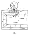
- la figure 1 est une vue en coupe longitudinale d'un répartiteur de coulée dans lequel est placée une machine d'application d'un revêtement de protection selon l'invention,
- la figure 2 est une vue en coupe à échelle agrandie selon le plan II-II de la figure 1,
- la figure 3 est une vue en plan partielle du répartiteur de coulée, montrant le dessus de la machine.
- Comme montré par les dessins annexés, le procédé pour réaliser un revêtement sur les faces latérales intérieures 2 d'un récipient métallurgique 1, destiné à recevoir du métal liquide, comporte les étapes suivantes :
- a) on positionne à une certaine distance de la face intérieure 2 dudit récipient une paroi mobile 3,
- b) on introduit entre la face 2 du récipient 1 et la paroi mobile 3, une composition 4 renfermant au moins une matière pulvérulente réfractaire, et
- c) on chauffe cette matière pulvérulente pour agglomérer au moins la surface devant venir au contact de l'acier liquide,
- d) on déplace ladite paroi mobile 3 et on répète les étapes précitées de façon à obtenir un revêtement continu sur lesdites faces du récipient 1.
- La composition pulvérulente 4 est introduite soit manuellement entre lesdites face et paroi mobile 3, soit à l'aide d'un dispositif assurant une alimentation constante entre lesdites face et paroi au fur et à mesure de l'avancement de la paroi mobile 3.
- On chauffe la matière pulvérulente 4 grâce au préchauffage d'au moins l'une desdites face 2 ou paroi mobile 3 aux environs de 190°C à 500°C pour les compositions pratiquement sèches puis jusqu'à 900°C si la composition renferme de l'eau de cristallisation ou de réhydratation ou si la décarbonatation de certains réfractaires est nécessaire ou encore aux environs de 1 300°C si l'on veut couler dans un récipient chaud.
- La matière pulvérulente réfractaire 4 est choisie parmi les matières suivantes : silice, alumine, magnésie, chrome-magnésie, dolomie crue, dolomie cuite, calcite, chaux, oxyde de chrome, silicate de zirconium, silico-alumineux et leur mélange.
- De préférence, la composition 4 renferme en outre un liant choisi parmi les liants minéraux, organiques, hydrauliques et leur mélange, la matière pulvérulente réfractaire pouvant être calibrée dans une classe de granulométrie très étendue et être préenrobée à l'aide d'au moins un liant.
- La matière pulvérulente peut présenter la composition pondérale suivante :
- matière pulvérulente réfractaire : 60 à 100%
- liant (ciment et/ou silicate et/ou résine : 0 à 20%
- matière carbonée : 0 à 20%.
- Par exemple, la composition peut renfermer :
20 à 0,5% de préférence 4% de liant (résine phénolique et/ou silicate et/ou ciment)
20 à 0%, de préférence 1,5% de produits d'allègement, par exemple farine de bois et/ou particules de papier,
99,5 à 60%, de préférence 94,5% de grains réfractaires, par exemple silice. - La composition présente dans cet exemple une densité de 1,10 à 1,40 environ.
- La composition peut encore être la suivante :
0 à 20% de liant, de préférence 4 % 0 à 20% de produits d'allègement, par exemple de farine de bois et/ou particules de papier de préférence 1 % 0 à 5% de lubrifiant (par exemple stéréate) de préférence 0,5 % 0 à 5% d'acide borique de préférence 1 % 100 à 50% de magnésie et/ou silice et/ou alumine et/ou dolomie et/ou chaux et/ou calcite et/ou sulfate et/ou phosphate et/ou zircon de préférence 93,5 %,
la composition présentant dans ce cas une densité comprise entre 1,6 et 2,2 environ. - La machine conforme à l'invention comprend au moins une paroi 3 mobile le long d'une face intérieure 2 du récipient 1 et formant avec cette face un espace 5 (voir figure 2) d'épaisseur sensiblement constante, correspondant à celle du revêtement à réaliser et des moyens pour introduire dans ledit espace 5 la composition pulvérulente 4 du revêtement à former.
- On voit sur les figures 1 à 3, que la paroi 3 porte à son extrémité inférieure un galet 6 qui prend appui sur le fond 7 du récipient 1 de telle sorte que cette extrémité de la paroi 3 touche pratiquement ce fond 7.
- L'extrémité supérieure de la paroi mobile 3 porte deux chapes 8 à l'intérieur desquelles sont montées en rotation des galets 9 prenant appui sur le bord supérieur 10 du récipient.
- Au dessus de la paroi mobile 3 se situe une trémie 11 renfermant la matière pulvérulente 4. Cette trémie 11 porte à sa partie inférieure un conduit 12 qui débouche au-dessus de l'espace 5 compris entre la face 2 du récipient et la paroi mobile 3.
- Cette trémie 11 peut se déplacer en même temps que la plaque mobile 3 entre les deux faces d'extrémité 13 du récipient 1.
- La paroi mobile 3 s'étend sur sensiblement toute la hauteur de la face latérale 2 du récipient 1 et ses bords latéraux 3a, 3b (voir figure 1) sont conformés de façon à épouser la forme des faces d'extrémité 13 du récipient. Ainsi lorsque le bord 3a, 3b vient en contact avec une face d'extrémité 13, ce bord réalise un joint sensiblement étanche avec cette face 13.
- Le bord 3b de la paroi 3 porte un rebord 3c (voir figure 3) qui ferme sensiblement l'espace 5 compris entre la paroi 3 et la face 2, ce qui évite toute fuite de matière pulvérulente par ce bord 3b.
- Par ailleurs, la paroi mobile 3 comporte des moyens de chauffage (non représentés) suffisants pour former par liaison chimique (par exemple du silicate) et/ou par liaison hydraulique (par exemple du ciment) et/ou par liaison céramique (par exemple frittage) et/ou par polymérisation (par exemple de la résine) de la matière pulvérulente une croûte dure 14 (voir figure 2) sur la surface de la composition pulvérulente 4 adjacente à cette paroi mobile 3, même si le récipient n'est pas lui-même chauffant, ou préchauffé.
- Ces moyens de chauffage peuvent être constitués par des résistances électriques ou par un dispositif chauffé au gaz portés par la paroi mobile 3.
- Au récipient 1 peut être adjoint, de préférence de manière non solidaire, un préchauffeur capable de préchauffer uniformément ledit récipient à une température d'au moins 110°C à coeur de manière à solidifier la composition 4 destinée à former le revêtement, même si la paroi mobile 3 n'est pas chauffante.
- La paroi mobile 3 est de préférence jumelée avec une paroi déplaçable sur le côté opposé du récipient dans le même sens ou en sens contraire, de façon à pouvoir réaliser un revêtement de protection en même temps sur les deux faces longitudinales 2.
- Le déplacement de la paroi mobile 3 (ou des deux parois) peut être commandée au moyen d'un robot.
- La machine comporte, en outre et de préférence, un dispositif permettant d'étaler et/ou de tasser la composition 4 devant donner lieu au revêtement se situant sur le fond 7 du récipient.
- Le dispositif pour étaler et/ou tasser (par exemple pneumatiquement) la composition 4 sur le fond 7 du récipient 1 comporte des moyens de chauffage permettant de solidifier ladite composition, notamment lorsque le récipient 1 est froid. Cette composition peut également être étalée manuellement sur le fond du récipient.
- Il est à noter, en particulier dans la zone se situant au-dessus du bain d'acier, la possibilité d'un risque de friabilité du revêtement du fait de la destruction du liant organique par la chaleur de rayonnement, ce handicap peut être surmonté par la présence d'un liant minéral complémentaire dans l'analyse dudit revêtement (du silicate par exemple). Si l'on veut, notamment pour certaines qualités d'aciers, couler dans un récipient chaud, le risque ci-dessus mentionné se pose pour l'ensemble du revêtement, on doit dans ce cas le préchauffer aux environs de :
1 200°C pour un mélange basique,
1 300/1 350°C pour un mélange siliceux et
1 200°C pour un mélange dolomitique, et/ou à base de chaux et/ou à base de calcite, et/ou à base d'hydroxydes, afin d'obtenir une liaison céramique de l'ensemble (par frittage).
Claims (16)
- Procédé pour réaliser un revêtement de protection sur les faces intérieures (2) d'un récipient métallurgique (1) destiné au transvasement de métal liquide, ce procédé comportant les étapes suivantes :a) on positionne à une certaine distance de la face intérieure (2) dudit récipient, au moins une paroi (3) s'étendant sensiblement sur toute la hauteur desdites faces,b) on introduit entre la face (2) du récipient et la paroi (3) une composition (4) renfermant au moins une matière pulvérulente réfractaire,c) on chauffe cette matière pulvérulente pour obtenir au moins le durcissement de ladite composition,
ce procédé étant caractérisé en ce qu'il comporte les étapes suivantes :d) on utilise une paroi (3) mobile s'étendant sensiblement sur toute la hauteur desdites faces ;e) on introduit entre la face (2) du récipientet la paroi mobile (3) une composition adaptée à durcir sous l'action de la chaleur ;f) on chauffe cette composition pour agglomérer au moins la surface devant venir au contact de l'acier liquide,g) on déplace ladite paroi mobile (3) transversalement le long desdites faces et on répète les étapes précitées de façon à obtenir un revêtement continu sur lesdites faces du récipient. - Procédé conforme à la revendication 1, caractérisé en ce que la composition pulvérulente (4) est introduite soit manuellement entre lesdites face et paroi mobile (3), soit à l'aide d'un dispositif assurant une alimentation constante entre lesdites face (2) et paroi (3) au fur et à mesure de l'avancement de la paroi mobile (3).
- Procédé conforme à l'une des revendications 1 ou 2, caractérisé en ce que l'on chauffe la matière pulvérulente (4) grâce au préchauffage d'au moins l'une desdites faces ou paroi mobile (3) aux environs de 190°C à 500°C pour les compositions pratiquement sèches puis jusqu'aux environs de 900°C si la composition renferme de l'eau de cristallisation ou de réhydratation ou si la décarbonatation de certaines matières réfractaires est nécessaire ou encore aux environs de 1 300°C (température de frittage du revêtement) si l'on veut couler dans un récipient chaud.
- Emploi pour la mise en oeuvre du procédé conforme à l'une des revendications 1 à 3, d'une composition renfermant au moins une matière pulvérulente réfractaire et étant capable de durcir et de s'agglomérer sous l'action de la chaleur, ladite matière pulvérulente réfractaire étant choisie parmi les matières suivantes : silice, alumine, magnésie, chrome-magnésie, dolomie crue, dolomie cuite, calcite, chaux, oxyde de chrome, silicate de zirconium, silico-alumineux et leur mélange .
- Emploi conforme à la revendication 4, la composition renfermant en outre un liant choisi parmi les liants minéraux, organiques, hydrauliques et leur mélange.
- Emploi conforme à l'une des revendications 4 ou 5, la composition présentant la composition pondérale suivante :- matière pulvérulente réfractaire : 60 à 100%- liant (ciment et/ou silicate et/ou résine) : 0 à 20%- matière carbonée : 0 à 20%.
- Emploi conforme à l'une des revendications 4 à 6, la composition renfermant :
20 à 0,5%, de préférence 4%, de liant (par exemple résine phénolique et/ou silicate et/ou ciment)
20 à 0%, de préférence 1,5%, de produits d'allègement, par exemple farine de bois et/ou particules de papier, et/ou fibres minérales et/ou organiques relativement courtes.
99,5 à 60%, de préférence 94,5%, de grains réfractaires, par exemple silice, la composition présentant une densité comprise entre 1,10 et 1,40 environ. - Emploi conforme à l'une des revendications 4 à 6, la composition renfermant :
0 à 20% de liant, de préférence 4 % 0 à 20% de produits d'allègement, par exemple de farine de bois et/ou particules de papier, de préférence 1 % 0 à 5% de lubrifiant (par exemple stéarate), de préférence 0,5 % 0 à 5% d'acide borique de préférence 1 % 100 à 50% de magnésie et/ou silice et/ou alumine et/ou dolomie et/ou chaux et/ou calcite et/ou sulfate et/ou phosphate et/ou zircon, de préférence 93,5 %, - Machine pour la mise en oeuvre du procédé selon l'une des revendications 1 à 3, comprenant au moins une paroi mobile (3) le long d'une face intérieure (2) du récipient (1) et formant avec cette face un espace (5) d'épaisseur sensiblement constante correspondant à celle du revêtement à réaliser, et des moyens pour introduire dans ledit espace (5) la composition pulvérulente du revêtement à former, caractérisée en ce que ladite paroi mobile (3) s'étend sur sensiblement toute la hauteur de la face du récipient (1).
- Machine conforme à la revendication 9, caractérisée en ce que ses bords (3a, 3b) latéraux sont conformés de façon à épouser la forme des faces d'extrémité (13) du récipient.
- Machine conforme à l'une des revendications 9 ou 10, caractérisée en ce que ladite paroi mobile (3) comporte des moyens de chauffage suffisants pour former une croûte dure (14) sur la surface de la composition pulvérulente (4) adjacente à cette paroi mobile, même si le récipient (1) n'est pas lui-même chauffant.
- Machine conforme à l'une des revendications 9 à 11, caractérisée en ce qu'au récipient (1) est adjoint, de préférence de manière non solidaire, un préchauffeur capable de préchauffer uniformément ledit récipient à une température d'au moins 110°C à coeur de manière à solidifier la composition destinée à former le revêtement, même si la paroi mobile n'est pas chauffante et/ou préchauffée.
- Machine conforme à l'une des revendications 9 à 12, caractérisée en ce que la paroi mobile (3) est jumelée avec une paroi déplaçable sur le côté opposé du récipient dans le même sens ou en sens contraire.
- Machine conforme à l'une des revendications 9 à 13, caractérisée en ce que le déplacement de la ou des parois mobiles (3) est commandé par un robot.
- Machine conforme à l'une des revendications 9 à 14, caractérisée en ce qu'elle comporte, en outre et de préférence, un dispositif permettant d'étaler et/ou de tasser la composition devant donner lieu au revêtement se situant sur le fond du récipient.
- Machine conforme à la revendication 15, caractérisée en ce que le dispositif pour étaler et/ou tasser par exemple pneumatiquement la composition sur le fond (7) du récipient comporte des moyens de chauffage permettant de solidifier ladite composition, notamment lorsque le récipient (1) est froid.
Applications Claiming Priority (3)
| Application Number | Priority Date | Filing Date | Title |
|---|---|---|---|
| FR8907150 | 1989-05-31 | ||
| FR8907150A FR2647779B1 (fr) | 1989-05-31 | 1989-05-31 | Procede pour realiser un revetement sur un recipient metallurgique, composition et machine pour sa mise en oeuvre |
| PCT/FR1990/000375 WO1990014909A1 (fr) | 1989-05-31 | 1990-05-30 | Procede pour realiser un revetement sur un recipient metallurgique, composition et machine pour sa mise en ×uvre |
Publications (2)
| Publication Number | Publication Date |
|---|---|
| EP0426834A1 EP0426834A1 (fr) | 1991-05-15 |
| EP0426834B1 true EP0426834B1 (fr) | 1994-07-27 |
Family
ID=9382202
Family Applications (1)
| Application Number | Title | Priority Date | Filing Date |
|---|---|---|---|
| EP90908955A Expired - Lifetime EP0426834B1 (fr) | 1989-05-31 | 1990-05-30 | Procede pour realiser un revetement sur un recipient metallurgique, composition et machine pour sa mise en oeuvre |
Country Status (10)
| Country | Link |
|---|---|
| US (1) | US5176873A (fr) |
| EP (1) | EP0426834B1 (fr) |
| AT (1) | ATE109048T1 (fr) |
| AU (1) | AU5747390A (fr) |
| CA (1) | CA2033201A1 (fr) |
| CS (1) | CS263190A3 (fr) |
| DE (1) | DE69011041T2 (fr) |
| FR (1) | FR2647779B1 (fr) |
| RO (1) | RO110794B1 (fr) |
| WO (1) | WO1990014909A1 (fr) |
Families Citing this family (8)
| Publication number | Priority date | Publication date | Assignee | Title |
|---|---|---|---|---|
| FR2695582B1 (fr) * | 1992-09-11 | 1994-12-23 | Lorraine Laminage | Dispositif de coulée du béton dans un réacteur métallurgique. |
| FR2732915B1 (fr) * | 1995-04-14 | 1997-06-13 | Daussan & Co | Procede pour appliquer a l'interieur d'un recipient metallurgique un revetement de protection comportant au moins deux couches |
| US7092520B2 (en) * | 1996-02-28 | 2006-08-15 | Nokia Corporation | Radiotelephone |
| FR2749200B1 (fr) * | 1996-05-29 | 1998-07-31 | Daussan & Co | Procede pour realiser un revetement comportant au moins deux couches sur les faces interieures d'un recipient tel qu'un recipient metallurgique et revetement ainsi obtenu |
| CH699405B1 (de) * | 2008-08-26 | 2021-06-15 | Mokesys Ag | Feuerfeste Wand, insbesondere für einen Verbrennungsofen. |
| JP5754295B2 (ja) * | 2011-08-17 | 2015-07-29 | 品川リフラクトリーズ株式会社 | ドライコーティング材 |
| CN107999732B (zh) * | 2017-11-07 | 2019-10-18 | 河钢股份有限公司承德分公司 | 超低碳涂抹料中间包的修砌方法 |
| CN110280750A (zh) * | 2019-08-02 | 2019-09-27 | 武汉精鼎科技股份有限公司 | 钢水罐罐壁工作层局部的修补方法 |
Family Cites Families (9)
| Publication number | Priority date | Publication date | Assignee | Title |
|---|---|---|---|---|
| DE1483584B2 (de) * | 1965-08-27 | 1971-03-11 | Schleuderformmaschine zum einbringen von beschichtungs material in eine giesspfanne | |
| DE1927816A1 (de) * | 1969-05-31 | 1970-12-03 | Plibrico Co Gmbh | Verfahren und Vorrichtung zum Ausbessern profilierter Wand- oder Deckenteile von Industrieoefen |
| FR2220163A5 (fr) * | 1973-03-02 | 1974-09-27 | Garreau Jean | |
| US3876354A (en) * | 1973-09-12 | 1975-04-08 | Shin Nippon Koki Co Ltd | Apparatus for automatically lining containers |
| GB1426135A (en) * | 1974-03-19 | 1976-02-25 | Novolipetsky Metall Z | Lining metallurgical vessels |
| US4218050A (en) * | 1974-11-22 | 1980-08-19 | Spribag Aktiengesellschaft | Apparatus and methods for automatically lining containers, especially casting ladles |
| US4117052A (en) * | 1975-03-19 | 1978-09-26 | Dorentruper Sand- Und Thonwerker G.M.B.H. | Method and arrangement for use in lining articles, particularly melting oven |
| US4589633A (en) * | 1984-01-26 | 1986-05-20 | Jacques Gilson | Process and installation for moulding a refractory lining of a container for liquid metal |
| SU1258608A2 (ru) * | 1985-05-22 | 1986-09-23 | Всесоюзный Проектно-Технологический Институт Литейного Производства | Машина дл футеровки металлургических ковшей |
-
1989
- 1989-05-31 FR FR8907150A patent/FR2647779B1/fr not_active Expired - Lifetime
-
1990
- 1990-05-29 CS CS902631A patent/CS263190A3/cs unknown
- 1990-05-30 DE DE69011041T patent/DE69011041T2/de not_active Expired - Fee Related
- 1990-05-30 US US07/635,546 patent/US5176873A/en not_active Expired - Fee Related
- 1990-05-30 RO RO146849A patent/RO110794B1/ro unknown
- 1990-05-30 AT AT90908955T patent/ATE109048T1/de not_active IP Right Cessation
- 1990-05-30 EP EP90908955A patent/EP0426834B1/fr not_active Expired - Lifetime
- 1990-05-30 WO PCT/FR1990/000375 patent/WO1990014909A1/fr not_active Ceased
- 1990-05-30 AU AU57473/90A patent/AU5747390A/en not_active Abandoned
- 1990-05-30 CA CA002033201A patent/CA2033201A1/fr not_active Abandoned
Non-Patent Citations (1)
| Title |
|---|
| Soviet Inventions Illustrated, week 8720, 27 May 1987, section C, class M, abstract No 87-141375/20, Derwent Publications Ltd, (Londres, GB), & SU, A, 1258608 (CASTING MFR. ENG. DES) 23 septembre 1986 * |
Also Published As
| Publication number | Publication date |
|---|---|
| AU5747390A (en) | 1991-01-07 |
| EP0426834A1 (fr) | 1991-05-15 |
| CS263190A3 (en) | 1992-03-18 |
| DE69011041D1 (de) | 1994-09-01 |
| FR2647779B1 (fr) | 1993-06-25 |
| RO110794B1 (ro) | 1996-04-30 |
| DE69011041T2 (de) | 1995-03-30 |
| US5176873A (en) | 1993-01-05 |
| FR2647779A1 (fr) | 1990-12-07 |
| CA2033201A1 (fr) | 1990-12-01 |
| WO1990014909A1 (fr) | 1990-12-13 |
| ATE109048T1 (de) | 1994-08-15 |
Similar Documents
| Publication | Publication Date | Title |
|---|---|---|
| US4182466A (en) | Wear part for sliding gates and process for the production of such wear parts and sliding gate with such wear parts | |
| AU678889B2 (en) | Dry refractory composition | |
| EP0426834B1 (fr) | Procede pour realiser un revetement sur un recipient metallurgique, composition et machine pour sa mise en oeuvre | |
| CA1198571A (fr) | Couche refractaire monolithique pour cuves de metallurgie, et sa deposition | |
| KR100224508B1 (ko) | 용융금속을 담는 벽부재 제조 및수선방법과 벽부재 형성용 몰드 | |
| CA1045333A (fr) | Cuves pour le transfert de metaux en fusion | |
| EP0086923A1 (fr) | Forme, procédé et composition pour le moulage par soufflage du revêtement réfractaire consommable d'un récipient destiné à contenir du métal en fusion | |
| GB2043221A (en) | Induction crucible furnace and a method of lining such a furnace | |
| FR2646367A1 (fr) | Procede et installation pour realiser un revetement sur les parois interieures d'un recipient metallurgique | |
| CA2439626A1 (fr) | Procede et appareil de creation de blocs de beton ayant l'apparence d'une pierre fossile naturelle | |
| JPH09316819A (ja) | 舗道における新旧舗装境界ラインのジョイントシール機 | |
| US5511762A (en) | Consumable form with degradable lining | |
| CN112475280B (zh) | 一种浇注料浇包及其制作方法 | |
| JP3945261B2 (ja) | スラグの鋳造方法および装置 | |
| US4279845A (en) | Process for coating the inner wall of a furnace or like apparatus | |
| CA1195472A (fr) | Coulee du metal, et poches chemisees connexes | |
| JP3506833B2 (ja) | タンディッシュ羽口の補修方法 | |
| US4783377A (en) | Tundish lid | |
| RU2182063C2 (ru) | Способ ремонта деталей с открытыми поверхностными дефектами | |
| RU2634818C1 (ru) | Способ получения стальных отливок из термитной шихты | |
| JPS59137163A (ja) | 耐火断熱性製品及び溶融金属取扱容器 | |
| JPS6372474A (ja) | 取鍋敷部の補修方法 | |
| RU2374030C2 (ru) | Способ изготовления форм отливок с применением самотвердеющих смесей с последующим уплотнением наполнительным составом | |
| HUT60789A (en) | Furnace pot for steel production and process for forming fireproof bottom lining of furnace pot | |
| RU2138366C1 (ru) | Способ футеровки сталеразливочного ковша |
Legal Events
| Date | Code | Title | Description |
|---|---|---|---|
| PUAI | Public reference made under article 153(3) epc to a published international application that has entered the european phase |
Free format text: ORIGINAL CODE: 0009012 |
|
| 17P | Request for examination filed |
Effective date: 19910108 |
|
| AK | Designated contracting states |
Kind code of ref document: A1 Designated state(s): AT BE CH DE DK ES GB IT LI LU NL SE |
|
| 17Q | First examination report despatched |
Effective date: 19920806 |
|
| GRAA | (expected) grant |
Free format text: ORIGINAL CODE: 0009210 |
|
| AK | Designated contracting states |
Kind code of ref document: B1 Designated state(s): AT BE CH DE DK ES GB IT LI LU NL SE |
|
| PG25 | Lapsed in a contracting state [announced via postgrant information from national office to epo] |
Ref country code: NL Effective date: 19940727 Ref country code: ES Free format text: THE PATENT HAS BEEN ANNULLED BY A DECISION OF A NATIONAL AUTHORITY Effective date: 19940727 Ref country code: DK Effective date: 19940727 Ref country code: AT Effective date: 19940727 |
|
| REF | Corresponds to: |
Ref document number: 109048 Country of ref document: AT Date of ref document: 19940815 Kind code of ref document: T |
|
| REF | Corresponds to: |
Ref document number: 69011041 Country of ref document: DE Date of ref document: 19940901 |
|
| ITF | It: translation for a ep patent filed | ||
| GBT | Gb: translation of ep patent filed (gb section 77(6)(a)/1977) |
Effective date: 19940901 |
|
| PG25 | Lapsed in a contracting state [announced via postgrant information from national office to epo] |
Ref country code: SE Effective date: 19941027 |
|
| NLV1 | Nl: lapsed or annulled due to failure to fulfill the requirements of art. 29p and 29m of the patents act | ||
| PGFP | Annual fee paid to national office [announced via postgrant information from national office to epo] |
Ref country code: LU Payment date: 19950501 Year of fee payment: 6 |
|
| PGFP | Annual fee paid to national office [announced via postgrant information from national office to epo] |
Ref country code: GB Payment date: 19950519 Year of fee payment: 6 |
|
| PGFP | Annual fee paid to national office [announced via postgrant information from national office to epo] |
Ref country code: DE Payment date: 19950523 Year of fee payment: 6 |
|
| PG25 | Lapsed in a contracting state [announced via postgrant information from national office to epo] |
Ref country code: LI Effective date: 19950531 Ref country code: CH Effective date: 19950531 |
|
| PLBE | No opposition filed within time limit |
Free format text: ORIGINAL CODE: 0009261 |
|
| STAA | Information on the status of an ep patent application or granted ep patent |
Free format text: STATUS: NO OPPOSITION FILED WITHIN TIME LIMIT |
|
| PGFP | Annual fee paid to national office [announced via postgrant information from national office to epo] |
Ref country code: BE Payment date: 19950706 Year of fee payment: 6 |
|
| 26N | No opposition filed | ||
| REG | Reference to a national code |
Ref country code: CH Ref legal event code: PL |
|
| PG25 | Lapsed in a contracting state [announced via postgrant information from national office to epo] |
Ref country code: LU Free format text: LAPSE BECAUSE OF NON-PAYMENT OF DUE FEES Effective date: 19960530 Ref country code: GB Effective date: 19960530 |
|
| PG25 | Lapsed in a contracting state [announced via postgrant information from national office to epo] |
Ref country code: BE Effective date: 19960531 |
|
| BERE | Be: lapsed |
Owner name: DAUSSAN ET CIE Effective date: 19960531 |
|
| GBPC | Gb: european patent ceased through non-payment of renewal fee |
Effective date: 19960530 |
|
| PG25 | Lapsed in a contracting state [announced via postgrant information from national office to epo] |
Ref country code: DE Effective date: 19970201 |
|
| PG25 | Lapsed in a contracting state [announced via postgrant information from national office to epo] |
Ref country code: IT Free format text: LAPSE BECAUSE OF NON-PAYMENT OF DUE FEES;WARNING: LAPSES OF ITALIAN PATENTS WITH EFFECTIVE DATE BEFORE 2007 MAY HAVE OCCURRED AT ANY TIME BEFORE 2007. THE CORRECT EFFECTIVE DATE MAY BE DIFFERENT FROM THE ONE RECORDED. Effective date: 20050530 |