EP0426953B1 - Arrêt de porte à fonctionnement mécanique pour portes de véhicules automobiles - Google Patents
Arrêt de porte à fonctionnement mécanique pour portes de véhicules automobiles Download PDFInfo
- Publication number
- EP0426953B1 EP0426953B1 EP90115086A EP90115086A EP0426953B1 EP 0426953 B1 EP0426953 B1 EP 0426953B1 EP 90115086 A EP90115086 A EP 90115086A EP 90115086 A EP90115086 A EP 90115086A EP 0426953 B1 EP0426953 B1 EP 0426953B1
- Authority
- EP
- European Patent Office
- Prior art keywords
- door
- stay according
- retaining bar
- plate assembly
- supporting housing
- Prior art date
- Legal status (The legal status is an assumption and is not a legal conclusion. Google has not performed a legal analysis and makes no representation as to the accuracy of the status listed.)
- Expired - Lifetime
Links
- 230000000977 initiatory effect Effects 0.000 claims abstract description 8
- 229910000831 Steel Inorganic materials 0.000 claims description 2
- 230000005540 biological transmission Effects 0.000 claims description 2
- 239000010959 steel Substances 0.000 claims description 2
- 238000006073 displacement reaction Methods 0.000 claims 3
- 230000000712 assembly Effects 0.000 claims 1
- 238000000429 assembly Methods 0.000 claims 1
- 238000010276 construction Methods 0.000 claims 1
- 238000004519 manufacturing process Methods 0.000 description 4
- 210000000078 claw Anatomy 0.000 description 3
- 241000446313 Lamella Species 0.000 description 2
- 238000011109 contamination Methods 0.000 description 1
- 238000009434 installation Methods 0.000 description 1
- 238000000034 method Methods 0.000 description 1
- 230000000149 penetrating effect Effects 0.000 description 1
- IHQKEDIOMGYHEB-UHFFFAOYSA-M sodium dimethylarsinate Chemical class [Na+].C[As](C)([O-])=O IHQKEDIOMGYHEB-UHFFFAOYSA-M 0.000 description 1
Images

Classifications
-
- E—FIXED CONSTRUCTIONS
- E05—LOCKS; KEYS; WINDOW OR DOOR FITTINGS; SAFES
- E05C—BOLTS OR FASTENING DEVICES FOR WINGS, SPECIALLY FOR DOORS OR WINDOWS
- E05C17/00—Devices for holding wings open; Devices for limiting opening of wings or for holding wings open by a movable member extending between frame and wing; Braking devices, stops or buffers, combined therewith
- E05C17/02—Devices for holding wings open; Devices for limiting opening of wings or for holding wings open by a movable member extending between frame and wing; Braking devices, stops or buffers, combined therewith by mechanical means
- E05C17/04—Devices for holding wings open; Devices for limiting opening of wings or for holding wings open by a movable member extending between frame and wing; Braking devices, stops or buffers, combined therewith by mechanical means with a movable bar or equivalent member extending between frame and wing
- E05C17/12—Devices for holding wings open; Devices for limiting opening of wings or for holding wings open by a movable member extending between frame and wing; Braking devices, stops or buffers, combined therewith by mechanical means with a movable bar or equivalent member extending between frame and wing consisting of a single rod
- E05C17/20—Devices for holding wings open; Devices for limiting opening of wings or for holding wings open by a movable member extending between frame and wing; Braking devices, stops or buffers, combined therewith by mechanical means with a movable bar or equivalent member extending between frame and wing consisting of a single rod sliding through a guide
- E05C17/203—Devices for holding wings open; Devices for limiting opening of wings or for holding wings open by a movable member extending between frame and wing; Braking devices, stops or buffers, combined therewith by mechanical means with a movable bar or equivalent member extending between frame and wing consisting of a single rod sliding through a guide concealed, e.g. for vehicles
Definitions
- the invention relates to a mechanical door arrester for motor vehicle doors, consisting of a holder housing arranged on one door arrangement part, door or door pillar, and a door holding rod articulated on the other door arrangement part, penetrating the holder housing, and a brake and holding device accommodated in the holder housing and interacting with the door holding rod.
- Mechanical door locks for motor vehicle doors of conventional design are essentially characterized in that one or more braking ramps are arranged along a length of a door holding rod, with which a braking or locking device in a holder housing interacts in such a way that the motor vehicle door is arranged in one or more predetermined ones Opening positions are braked and held.
- Door locks of this type intended for motor vehicle doors are somewhat disadvantageous in that they only allow the door to be locked in certain opening positions, which often results in the risk of damage to the vehicle's own door or to the neighboring one when parking in confined spaces or in garages Can bring vehicle through the undetected vehicle door.
- the invention is based on the object of providing a mechanical door arrester for motor vehicle doors which, if necessary, enables the door to be securely locked in any open position with the least possible manufacturing and assembly effort and, moreover, complete freedom of movement of the vehicle door.
- the Holding device comprises at least one lamella which can be brought into frictional engagement with the door holding rod and is tiltably supported in the holder housing and an adjusting element associated with the initiation of the tilting movement of the lamella.
- the holding device comprises at least one slat package which can be brought into frictional engagement with the door holding rod and is tiltably supported in the holder housing, and an adjusting element associated with the initiation of the tilting movement of the slat package.
- a plate pack as a braking or locking means allows the vehicle door to be locked in any open position and guarantees high braking and locking forces on the one hand and furthermore has the advantage that the door lock can be manufactured easily.
- a door arrester works without noise and such a door arrester is relatively insensitive to inevitable contamination of the door holding rod.
- the adjusting element associated with the initiation of the tilting movement of the slats can be adjusted by means of a remote control, whereby the arrangement can also be such that the adjusting element associated with the initiation of the tilting movement of the plate assembly is actuated by means of an actuating lever and a transmission means, in particular is manually operable by means of a Bowden cable.
- the actuating lever can either be arranged in the region of the door handle, or it can also be connected to the door handle, so that the door arrester is automatically released when the door is opened or closed.
- At least one slat package comprising a number of slats penetrated by the door holding rod is provided, which is tiltably supported on the holder housing and on the other hand by means of of an adjusting element against a resilient spring load is adjustable in a tilted position.
- the adjustment element is pivotable about an axis running transversely to the longitudinal axis of the door holding rod and the rocker arm of the plate pack opposite to the tilt support is formed in the holder housing and acts on the plate pack by means of a pressure plate.
- the spring load acting as a return spring on the disk pack is formed by a bracket spring which is fixed on the holder housing and encompasses one side of the disk pack and rests with at least one of its legs on an end face of the disk pack and that in connection with
- the tilt support of the disk pack is formed by a bolt with a round cross section aligned in the side walls of the holder housing and oriented transversely to the longitudinal axis of the holder housing or the door holding rod.
- a particularly inexpensive, easy-to-assemble design results from such a door arrester in that, on the one hand, the rocker arm and, on the other hand, the bow spring acting as a return spring on the disk pack is assigned an abutment formed by a transverse wall of the holder housing, expediently providing that this
- the rocker arm and the return spring associated abutment forming transverse wall of the holder housing is formed by pressure plates supported against the string side of a cup-shaped holder housing which is open on one side.
- the pressure plates forming the abutment can be held in contact by the return spring designed as a bow spring on the end face of the holder housing.
- the rocker arm forming the adjusting element is designed as a double-armed lever.
- the bow spring forming the return spring has two spring legs of different lengths on both sides of a base that engages under the plate pack.
- the lamellae are formed by steel plates and are symmetrical in terms of their recess penetrated by the door holding rod, so that no particular consideration of a particular alignment of the individual lamellae need be taken during assembly .
- the door holding rod can have any cross-sectional profile, but in the interest of standardization it will expediently have a symmetrical geometric and in particular a circular cross-sectional shape.
- the holder housing is suspended via rivet bolts about an axis directed perpendicular to the longitudinal axis of the door retaining rod between two fastening claws arranged opposite one another in a vertical direction.
- the operation of the door lock can also be designed so that the door is locked automatically depending on a standstill of the door in an open position, for example by the fact that the slats are constantly in contact with the door support rod and with regard to their permitted tilting movement are limited to an amount that is only suitable for generating an increase in the frictional force that is sufficient for the determination of the door.
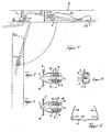
- the door holding rod 2 of a door arrester is articulated on the door pillar 5 of the vehicle body by means of a bearing block 3 about an axis 4 parallel to the door hinge axis.
- the holder housing 7 is generally pot-shaped and is suspended from two mutually opposite fastening claws 9 via two rivet bolts 8 aligned vertically and perpendicular to the longitudinal axis of the door holding rod 2, the fixing claws 9 in turn being fastened to the string wall 10 of the door body 6 .
- a plate pack 11 Arranged within the holder housing 7 is a plate pack 11 formed from a number of plates, the plates 11 each having a recess 12, which is arranged centrally and symmetrically to the shape of the plates 11 and is penetrated by the door holding rod 2.
- the fins 11 are at one Supported against a pin 13 forming a tilting bearing and fastened transversely to the longitudinal axis of the door holding rod 2 in the holder housing 7 and can be acted upon on its opposite side by a tilting lever 14 forming an adjusting element.
- the rocker arm 14 is designed as a double-armed lever and is pivotably suspended in the holder housing 7 about an axis 15 aligned transversely to the longitudinal axis of the door holding rod 2.
- the rocker arm 14 interacts with the plate pack 11 via its one lever arm 16 by means of a pressure plate 17.
- the rocker arm 14 is assigned an abutment on which the rocker arm 14 is supported by its second lever arm 18.
- the abutment is formed by abutment plates 19, which in turn are supported on the holder housing 7 on the open end face thereof.
- the slats 11 of the plate pack are, as can be seen in particular from the illustration in FIG.
- the plate pack 11 is loaded by the force of a return spring, which in the exemplary embodiment shown is formed by a bow spring 21 and, on the basis of a leaf-shaped base 22 which engages under the plate pack 11 and the pressure plates 17, is equipped at both ends with two differently long spring legs 23 and 24 and on one side is supported with its two spring legs 23 and 24 on the pressure plates 17, while on the other side it rests with its two spring legs 23 and 24 on the outside of the plate pack 11.
- the door lock 1 shown in the exemplary embodiment can be actuated manually with regard to the fixing and release of the vehicle door, in such a way that the rocker arm 14 by means of a hand or.
- Operating lever 30 and a Bowden cable 31 connecting it to the rocker arm 14 can be moved back and forth between its operative position and its release position.
- the actuating lever 30 is preferably arranged in the vicinity of or directly on a door handle or the like.
- two disk packs 111 are arranged on both sides of a double-armed rocker arm 140 in a trough-shaped holder housing 70, the two disk packs 111 each being loaded in the return direction by the two spring legs 23 and 24 of a bow spring 20 which engages under the disk packs 111.
- a special support of the disk packs or the rocker arm with respect to the holder housing 70 is not required, since the two disk packs 111 are adjusted in opposite directions by the double-arm rocker arm 140.
Landscapes
- Engineering & Computer Science (AREA)
- Mechanical Engineering (AREA)
- Lock And Its Accessories (AREA)
- Fittings On The Vehicle Exterior For Carrying Loads, And Devices For Holding Or Mounting Articles (AREA)
- Closing And Opening Devices For Wings, And Checks For Wings (AREA)
Claims (18)
- Arrêtoir de porte mécanique pour portes de véhicules automobiles, comportant:- un boîtier de maintien (7), disposé sur l'une des parties de la porte, savoir la porte elle-même (6) ou le montant de porte (5),- une barre d'arrêt (2) articulée sur l'autre partie de la porte et traversant le boîtier de maintien (7),- un dispositif de freinage et de blocage (11) logé dans le boîtier de maintien (2), pouvant basculer et coopérant par serrage avec la barre d'arrêt (2),caractérisé en ce que le dispositif de freinage et de blocage comprend au moins une lamelle (11) disposée dans le boîtier de maintien (7) en pouvant basculer et venir au contact par friction avec la barre d'arrêt (2), et, un élément de réglage (16) commandé à distance et commandant lui-même le basculement de la lamelle (11).
- Arrêtoir de porte selon la revendication 1 caractérisé en ce que le dispositif de freinage et de blocage comprend au moins un paquet de lamelles (11) disposé dans le boîtier de maintien (7) en pouvant basculer, et, un élément de réglage (16) commandé à distance et commandant lui-même le basculement du paquet de lamelles (11).
- Arrêtoir de porte selon les revendications 1 et 2 caractérisé en ce que l'élément de réglage commandant le basculement du paquet de lamelles (11) est actionné manuellement par un levier de manoeuvre (30) et un élément de transmission (31).
- Arrêtoir de porte selon les revendications 1 à 3 caractérisé en ce que au moins un paquet de lamelles (11) composé d'un certain nombre de lamelles traversées par la barre d'arrêt (2), s'appuie sur le boîtier de maintien (7) et peut basculer, grâce à un élément de réglage (14), à l'encontre de la force d'un ressort (21).
- Arrêtoir de porte selon les revendications 1 à 4 caractérisé en ce que l'élément de réglage qui agit sur le paquet de lamelles (11) par l'intermédiaire d'une plaque de pression (17), est constitué d'un levier basculant (14) disposé dans le boîtier de maintien (7) en faisant face à l'appui (13) du paquet de lamelles (11) et pouvant basculer autour d'un axe (15) perpendiculaire à l'axe longitudinal de la barre d'arrêt (2).
- Arrêtoir de porte selon les revendications 1 à 5 caractérisé en ce que le ressort agissant comme ressort de rappel sur le paquet de lamelles (11) est constitué d'un ressort en forme d'étrier (21) assemblé avec le boîtier de maintien (7), entourant le paquet de lamelles (11) d'un côté et s'appuyant sur un côté frontal du paquet de lamelles (11) par au moins l'une de ses branches (23), (24).
- Arrêtoir de porte selon les revendications 1 à 6 caractérisé en ce que l'articulation du paquet de lamelles (11) est constitué d'un boulon (13), orienté perpendiculairement à l'axe longitudinal du boîtier de maintien (7), respectivement de la barre d'arrêt (2), et s'appuyant sur les parois latérales du boîtier de maintien (7).
- Arrêtoir de porte selon les revendications 1 à 7 caractérisé en ce que d'une part, le levier basculant (14) et, d'autre part, le ressort en forme d'étrier (21) agissant comme ressort de rappel sur le paquet de lamelles, coopèrent avec une contre-butée constituée par une paroi transversale du boîtier de maintien (7).
- Arrêtoir de porte selon les revendications 1 à 8 caractérisé en ce que la contre-butée coopérant avec le levier basculant (14) et le ressort de rappel (21) est constituée de plaques de pression (19) disposées sur le côté frontal d'un boîtier de maintien (7) en forme de pot, ouvert d'un côté.
- Arrêtoir de porte selon les revendications 1 à 9 caractérisé en ce que les plaques de pression constituant la contre-butée sont maintenues appuyées sur le côté frontal du boîtier de maintien (7) par le ressort en forme d'étier (21) agissant comme ressort de rappel.
- Arrêtoir de porte selon les revendications 1 à 10 caractérisé en ce que le levier basculant (14) constituant l'élément de réglage est un levier à deux bras.
- Arrêtoir de porte selon les revendications 1 à 11 caractérisé en ce que le ressort en forme d'étrier (21) constituant le ressort de rappel comporte de part et d'autre de sa base (22) qui passe sous le paquet de lamelles (11), deux branches de ressort (23), (24) de longueur différente.
- Arrêtoir de porte selon les revendications 1 à 12 caractérisé en ce que les lamelles (11) qui sont constituées par des plaques en acier, sont de conformation symétrique par rapport à leur trou traversé par la barre d'arrêt (2).
- Arrêtoir de porte selon les revendications 1 à 13 caractérisé en ce que le boîtier de maintien (7) qui est suspendu par des boulons rivés (8) à deux pattes de fixation (9) disposées en face l'une de l'autre en direction verticale, est mobile autour d'un axe perpendiculaire à l'axe longitudinal de la barre d'arrêt (2).
- Arrêtoir de porte selon les revendications 1 à 14 caractérisé en ce que la barre d'arrêt (2) présente une section transversale de profilé circulaire.
- Arrêtoir de porte selon les revendications 1 à 14 caractérisé en ce que la barre d'arrêt (2) présente une section transversale de profilé de forme quelconque.
- Arrêtoir de porte selon la revendication 1 caractérisé en ce que pour une barre d'arrêt (2) présentant des zones de mouvement libre, les lamelles (11) sont en contact permanent avec la barre d'arrêt, en ce que leur mouvement de basculement est limité à une ampleur adaptée à la seule production d'un accroissement de la force de friction, suffisant pour assurer le blocage de la porte et en ce que l'élément de réglage est constitué d'une force de ressort provoquant le basculement des lamelles (11) lors de l'arrêt du mouvement de la barre d'arrêt (2).
- Arrêtoir de porte selon l'une ou plusieurs revendications 1 à 17 caractérisé par deux paquets de lamelles (111), disposés dans un boîtier de maintien (70) en forme d'auge, symétriquement de part et d'autre d'un élément de réglage constitué d'un levier basculant (140).
Priority Applications (1)
| Application Number | Priority Date | Filing Date | Title |
|---|---|---|---|
| AT90115086T ATE95272T1 (de) | 1989-11-08 | 1990-08-06 | Mechanischer tuerfeststeller fuer kraftwagentueren. |
Applications Claiming Priority (2)
| Application Number | Priority Date | Filing Date | Title |
|---|---|---|---|
| DE3937218A DE3937218A1 (de) | 1989-11-08 | 1989-11-08 | Mechanischer tuerfeststeller fuer kraftwagentueren |
| DE3937218 | 1989-11-08 |
Publications (2)
| Publication Number | Publication Date |
|---|---|
| EP0426953A1 EP0426953A1 (fr) | 1991-05-15 |
| EP0426953B1 true EP0426953B1 (fr) | 1993-09-29 |
Family
ID=6393132
Family Applications (1)
| Application Number | Title | Priority Date | Filing Date |
|---|---|---|---|
| EP90115086A Expired - Lifetime EP0426953B1 (fr) | 1989-11-08 | 1990-08-06 | Arrêt de porte à fonctionnement mécanique pour portes de véhicules automobiles |
Country Status (4)
| Country | Link |
|---|---|
| EP (1) | EP0426953B1 (fr) |
| AT (1) | ATE95272T1 (fr) |
| DE (2) | DE3937218A1 (fr) |
| ES (1) | ES2044344T3 (fr) |
Cited By (1)
| Publication number | Priority date | Publication date | Assignee | Title |
|---|---|---|---|---|
| DE102005005891A1 (de) * | 2005-02-09 | 2006-08-24 | Hs Genion Gmbh | Tür mit Türbremse |
Families Citing this family (7)
| Publication number | Priority date | Publication date | Assignee | Title |
|---|---|---|---|---|
| DE9201226U1 (de) * | 1991-09-16 | 1992-03-26 | Siegmüller GmbH, 5014 Kerpen | Vorrichtung zum Feststellen einer Tür, insbesondere einer Kraftfahrzeug-Tür, in mindestens einer Öffnungsstellung |
| DE4130782C2 (de) * | 1991-09-16 | 1994-02-24 | Siegmueller Gmbh | Vorrichtung zum Feststellen einer Tür, insbesondere einer Kraftfahrzeug-Tür, in mindestens einer Öffnungsstellung |
| FR2690653B1 (fr) * | 1992-04-29 | 1995-09-29 | Coutier Moulage Gen Ind | Arret de porte, notamment de porte de vehicule automobile. |
| FR2777934A1 (fr) * | 1998-04-23 | 1999-10-29 | Coutier Moulage Gen Ind | Arret de porte a position d'arret indefinie pour portiere de vehicule |
| DE102005015667A1 (de) * | 2005-04-06 | 2006-10-12 | Daimlerchrysler Ag | Türfeststelleinrichtung |
| DE202017105454U1 (de) | 2017-09-08 | 2017-10-12 | Wilhelm Eudenbach | Vorrichtung zum Feststellen oder Abbremsen einer Kraftfahrzeugtür |
| DE102017120772A1 (de) | 2017-09-08 | 2019-03-14 | Wilhelm Eudenbach | Vorrichtung zum Feststellen oder Abbremsen einer Kraftfahrzeugtür |
Family Cites Families (2)
| Publication number | Priority date | Publication date | Assignee | Title |
|---|---|---|---|---|
| GB816380A (en) * | 1956-01-26 | 1959-07-15 | Rudolph Ignatius Schonitzer | Holding device for doors and other pivoted structures |
| FR2592913A1 (fr) * | 1986-01-13 | 1987-07-17 | Bonin Lucien | Systeme destine a marquer la position relative d'un element mobile par rapport a un element fixe notamment pour portieres de vehicule. |
-
1989
- 1989-11-08 DE DE3937218A patent/DE3937218A1/de not_active Withdrawn
-
1990
- 1990-08-06 EP EP90115086A patent/EP0426953B1/fr not_active Expired - Lifetime
- 1990-08-06 AT AT90115086T patent/ATE95272T1/de not_active IP Right Cessation
- 1990-08-06 DE DE90115086T patent/DE59002921D1/de not_active Expired - Fee Related
- 1990-08-06 ES ES90115086T patent/ES2044344T3/es not_active Expired - Lifetime
Cited By (2)
| Publication number | Priority date | Publication date | Assignee | Title |
|---|---|---|---|---|
| DE102005005891A1 (de) * | 2005-02-09 | 2006-08-24 | Hs Genion Gmbh | Tür mit Türbremse |
| DE102005005891B4 (de) * | 2005-02-09 | 2009-07-30 | Hs Genion Gmbh | Tür mit Türbremse |
Also Published As
| Publication number | Publication date |
|---|---|
| EP0426953A1 (fr) | 1991-05-15 |
| ATE95272T1 (de) | 1993-10-15 |
| ES2044344T3 (es) | 1994-01-01 |
| DE3937218A1 (de) | 1991-05-16 |
| DE59002921D1 (de) | 1993-11-04 |
Similar Documents
| Publication | Publication Date | Title |
|---|---|---|
| DE3625691C2 (fr) | ||
| EP3044031B1 (fr) | Unité de verrouillage pour siège de véhicule et siège de véhicule | |
| EP4234864B1 (fr) | Arrêt de porte | |
| EP0235548B1 (fr) | Barrière de voie ou de passage pour véhicules | |
| EP3268244B1 (fr) | Unité de verrouillage pour siège de véhicule, et siège de véhicule | |
| EP3835526B1 (fr) | Système de battant coulissant et tournant | |
| EP0326823A1 (fr) | Bras de compas mécanique pour véhicules automobiles | |
| EP0426953A1 (fr) | Arrêt de porte à fonctionnement mécanique pour portes de véhicules automobiles | |
| EP0341371A2 (fr) | Charnière pour arrêt de porte | |
| EP0252314A2 (fr) | Serrure de direction à blocage du mouvement de rotation de la colonne de direction d'un véhicule automobile | |
| EP1277611A1 (fr) | Charnière extérieure pour la fixation d'un dossier | |
| DE4313570C2 (de) | Sicherheitsverriegelung für Fahrzeugabdeckungen | |
| DE9412661U1 (de) | Verriegelungsvorrichtung | |
| EP0623492B1 (fr) | Dispositif à arceau de sécurité pour un véhicule automobile | |
| DE1915751B2 (de) | Schwenklagerung für Türhaltebänder von Türfeststellern für Kraftwagentüren | |
| DE3507305C2 (de) | Vorrichtung zur Betätigung eines Freigaberiegels | |
| DE8913229U1 (de) | Mechanischer Türfeststeller für Kraftwagentüren | |
| DE3937220A1 (de) | Tuerfeststeller fuer kraftwagentueren | |
| EP0426952B1 (fr) | Charnière de porte combinée dans sa construction avec un arrêt de porte | |
| DE19506667A1 (de) | Griffeinheit für eine Kraftfahrzeugtür | |
| DE10042282A1 (de) | Türverkrallung | |
| EP0523401B1 (fr) | Dispositif de sécurité pour charnière de porte combinée dans sa construction avec un arrêt de porte | |
| WO2004055301A2 (fr) | Procede et dispositif pour fermer des portes coulissantes | |
| CH672654A5 (fr) | ||
| DE9101203U1 (de) | Türbremse für Kraftwagentüren |
Legal Events
| Date | Code | Title | Description |
|---|---|---|---|
| PUAI | Public reference made under article 153(3) epc to a published international application that has entered the european phase |
Free format text: ORIGINAL CODE: 0009012 |
|
| 17P | Request for examination filed |
Effective date: 19901220 |
|
| AK | Designated contracting states |
Kind code of ref document: A1 Designated state(s): AT BE DE ES FR GB IT NL SE |
|
| 17Q | First examination report despatched |
Effective date: 19920730 |
|
| GRAA | (expected) grant |
Free format text: ORIGINAL CODE: 0009210 |
|
| AK | Designated contracting states |
Kind code of ref document: B1 Designated state(s): AT BE DE ES FR GB IT NL SE |
|
| REF | Corresponds to: |
Ref document number: 95272 Country of ref document: AT Date of ref document: 19931015 Kind code of ref document: T |
|
| RIN1 | Information on inventor provided before grant (corrected) |
Inventor name: KLUETING, BERND ALFRED, DIPL. ING. |
|
| ET | Fr: translation filed | ||
| REF | Corresponds to: |
Ref document number: 59002921 Country of ref document: DE Date of ref document: 19931104 |
|
| GBT | Gb: translation of ep patent filed (gb section 77(6)(a)/1977) |
Effective date: 19931020 |
|
| ITF | It: translation for a ep patent filed | ||
| REG | Reference to a national code |
Ref country code: ES Ref legal event code: FG2A Ref document number: 2044344 Country of ref document: ES Kind code of ref document: T3 |
|
| PLBE | No opposition filed within time limit |
Free format text: ORIGINAL CODE: 0009261 |
|
| STAA | Information on the status of an ep patent application or granted ep patent |
Free format text: STATUS: NO OPPOSITION FILED WITHIN TIME LIMIT |
|
| 26N | No opposition filed | ||
| EAL | Se: european patent in force in sweden |
Ref document number: 90115086.2 |
|
| PGFP | Annual fee paid to national office [announced via postgrant information from national office to epo] |
Ref country code: BE Payment date: 19950926 Year of fee payment: 6 |
|
| PGFP | Annual fee paid to national office [announced via postgrant information from national office to epo] |
Ref country code: GB Payment date: 19960619 Year of fee payment: 7 |
|
| PGFP | Annual fee paid to national office [announced via postgrant information from national office to epo] |
Ref country code: ES Payment date: 19960807 Year of fee payment: 7 |
|
| PGFP | Annual fee paid to national office [announced via postgrant information from national office to epo] |
Ref country code: AT Payment date: 19960814 Year of fee payment: 7 |
|
| PGFP | Annual fee paid to national office [announced via postgrant information from national office to epo] |
Ref country code: FR Payment date: 19960823 Year of fee payment: 7 |
|
| PGFP | Annual fee paid to national office [announced via postgrant information from national office to epo] |
Ref country code: SE Payment date: 19960829 Year of fee payment: 7 |
|
| PG25 | Lapsed in a contracting state [announced via postgrant information from national office to epo] |
Ref country code: BE Effective date: 19960831 |
|
| PGFP | Annual fee paid to national office [announced via postgrant information from national office to epo] |
Ref country code: NL Payment date: 19960831 Year of fee payment: 7 |
|
| BERE | Be: lapsed |
Owner name: ED. SCHARWACHTER G.M.B.H. & CO. K.G. Effective date: 19960831 |
|
| PG25 | Lapsed in a contracting state [announced via postgrant information from national office to epo] |
Ref country code: GB Free format text: LAPSE BECAUSE OF NON-PAYMENT OF DUE FEES Effective date: 19970806 Ref country code: AT Free format text: LAPSE BECAUSE OF NON-PAYMENT OF DUE FEES Effective date: 19970806 |
|
| PG25 | Lapsed in a contracting state [announced via postgrant information from national office to epo] |
Ref country code: SE Free format text: LAPSE BECAUSE OF NON-PAYMENT OF DUE FEES Effective date: 19970807 Ref country code: ES Free format text: LAPSE BECAUSE OF THE APPLICANT RENOUNCES Effective date: 19970807 |
|
| PG25 | Lapsed in a contracting state [announced via postgrant information from national office to epo] |
Ref country code: NL Free format text: LAPSE BECAUSE OF NON-PAYMENT OF DUE FEES Effective date: 19980301 |
|
| GBPC | Gb: european patent ceased through non-payment of renewal fee |
Effective date: 19970806 |
|
| PG25 | Lapsed in a contracting state [announced via postgrant information from national office to epo] |
Ref country code: FR Free format text: LAPSE BECAUSE OF NON-PAYMENT OF DUE FEES Effective date: 19980430 |
|
| EUG | Se: european patent has lapsed |
Ref document number: 90115086.2 |
|
| NLV4 | Nl: lapsed or anulled due to non-payment of the annual fee |
Effective date: 19980301 |
|
| REG | Reference to a national code |
Ref country code: FR Ref legal event code: ST |
|
| REG | Reference to a national code |
Ref country code: ES Ref legal event code: FD2A Effective date: 20001009 |
|
| PGFP | Annual fee paid to national office [announced via postgrant information from national office to epo] |
Ref country code: DE Payment date: 20020809 Year of fee payment: 13 |
|
| PG25 | Lapsed in a contracting state [announced via postgrant information from national office to epo] |
Ref country code: DE Free format text: LAPSE BECAUSE OF NON-PAYMENT OF DUE FEES Effective date: 20040302 |
|
| PG25 | Lapsed in a contracting state [announced via postgrant information from national office to epo] |
Ref country code: IT Free format text: LAPSE BECAUSE OF NON-PAYMENT OF DUE FEES;WARNING: LAPSES OF ITALIAN PATENTS WITH EFFECTIVE DATE BEFORE 2007 MAY HAVE OCCURRED AT ANY TIME BEFORE 2007. THE CORRECT EFFECTIVE DATE MAY BE DIFFERENT FROM THE ONE RECORDED. Effective date: 20050806 |