EP0427330A2 - Verfahren und Vorrichtung zum gleichzeitigen Lesen beider Seiten einer optischen Speicherplatte - Google Patents
Verfahren und Vorrichtung zum gleichzeitigen Lesen beider Seiten einer optischen Speicherplatte Download PDFInfo
- Publication number
- EP0427330A2 EP0427330A2 EP90202907A EP90202907A EP0427330A2 EP 0427330 A2 EP0427330 A2 EP 0427330A2 EP 90202907 A EP90202907 A EP 90202907A EP 90202907 A EP90202907 A EP 90202907A EP 0427330 A2 EP0427330 A2 EP 0427330A2
- Authority
- EP
- European Patent Office
- Prior art keywords
- disk
- plate
- optical
- lead screw
- base plate
- Prior art date
- Legal status (The legal status is an assumption and is not a legal conclusion. Google has not performed a legal analysis and makes no representation as to the accuracy of the status listed.)
- Granted
Links
Images


Classifications
-
- G—PHYSICS
- G11—INFORMATION STORAGE
- G11B—INFORMATION STORAGE BASED ON RELATIVE MOVEMENT BETWEEN RECORD CARRIER AND TRANSDUCER
- G11B7/00—Recording or reproducing by optical means, e.g. recording using a thermal beam of optical radiation by modifying optical properties or the physical structure, reproducing using an optical beam at lower power by sensing optical properties; Record carriers therefor
- G11B7/12—Heads, e.g. forming of the optical beam spot or modulation of the optical beam
- G11B7/14—Heads, e.g. forming of the optical beam spot or modulation of the optical beam specially adapted to record on, or to reproduce from, more than one track simultaneously
-
- G—PHYSICS
- G11—INFORMATION STORAGE
- G11B—INFORMATION STORAGE BASED ON RELATIVE MOVEMENT BETWEEN RECORD CARRIER AND TRANSDUCER
- G11B17/00—Guiding record carriers not specifically of filamentary or web form, or of supports therefor
- G11B17/02—Details
- G11B17/04—Feeding or guiding single record carrier to or from transducer unit
- G11B17/041—Feeding or guiding single record carrier to or from transducer unit specially adapted for discs contained within cartridges
-
- G—PHYSICS
- G11—INFORMATION STORAGE
- G11B—INFORMATION STORAGE BASED ON RELATIVE MOVEMENT BETWEEN RECORD CARRIER AND TRANSDUCER
- G11B7/00—Recording or reproducing by optical means, e.g. recording using a thermal beam of optical radiation by modifying optical properties or the physical structure, reproducing using an optical beam at lower power by sensing optical properties; Record carriers therefor
- G11B7/08—Disposition or mounting of heads or light sources relatively to record carriers
-
- G—PHYSICS
- G11—INFORMATION STORAGE
- G11B—INFORMATION STORAGE BASED ON RELATIVE MOVEMENT BETWEEN RECORD CARRIER AND TRANSDUCER
- G11B7/00—Recording or reproducing by optical means, e.g. recording using a thermal beam of optical radiation by modifying optical properties or the physical structure, reproducing using an optical beam at lower power by sensing optical properties; Record carriers therefor
- G11B7/08—Disposition or mounting of heads or light sources relatively to record carriers
- G11B7/085—Disposition or mounting of heads or light sources relatively to record carriers with provision for moving the light beam into, or out of, its operative position or across tracks, otherwise than during the transducing operation, e.g. for adjustment or preliminary positioning or track change or selection
- G11B7/0857—Arrangements for mechanically moving the whole head
- G11B7/08582—Sled-type positioners
Definitions
- This invention relates in general to optical storage disk devices, and in particular to a method and apparatus for simultaneously reading both sides of an optical storage disk.
- optical storage disks for the recording of data has become a frequently used option.
- Data can be stored on a top and bottom side of the optical storage disk to increase the storage capacity of the disk.
- optical storage disk readers unlike magnetic storage disk readers, optical storage disk readers generally do not allow simultaneous reading of both sides of an optical storage disk. In those few devices allowing both sides of an optical disk to be read simultaneously, the device is generally a fixed media device capable of using only fixed disks.
- optical storage disk readers it is essential to keep the beam of light used to read and/or imprint the disk perpendicular to the surface thereof.
- the spot from the beam on the disk degrades (for optical reasons) as the beam varies from a perfectly perpendicular orientation.
- a double side reader it is necessary to provide a device that can maintain the vertical relationship between both sides of an optical disk and the optical readers associated therewith.
- optical storage disks can typically vary in thickness from approximately 2.75 mm to approximately 3.50 mm. These thickness variation are due to the disk construction by various manufacturers and the coatings which are applied thereto for the recording of data.
- it is necessary to have optical devices capable of adjustably focusing on each surface while maintaining a perpendicular relationship to both sides.
- a method and apparatus capable of simultaneously focusing on both sides of a single optical storage disk of varying thickness for simultaneous reading of the two sides.
- the present invention disclosed herein describes a method and apparatus for simultaneously reading both sides of an optical storage disk which eliminates or substantially reduces problems associated with prior optical storage disk reading devices.
- the present invention allows the simultaneous reading of both sides of disks that vary in thickness without the need for relatively expensive optical mechanisms.
- an optical storage disk encased within a cartridge is inserted into an optical reading device.
- Channels are provided for holding the cartridge in a fixed position relative to the storage disk by the case containing the optical reading device.
- a lower base plate including a spindle and a drive motor for rotating the disk is moved into position so that the optical disk is fixed parallel to and a known distance from the lower base plate.
- an upper base plate is positioned parallel to the lower base plate and at a predetermined distance therefrom corresponding to the proper focal distance to the thinnest optical storage disk available. From this point, optics associated with the upper base plate provide data that allow the upper base plate to move to the proper focal distance from the disk. While the upper plate moves, the lower plate also moves to maintain the parallel orientation between the lower base plate, the optical storage disk and the upper base plate.
- the upper and lower optical reading devices are moved radially with respect to the disk along slides to allow reading thereof.
- the upper and lower base plates are positioned by being raised or lowered as they pivot about hinges.
- Each base plate is hinged on one edge to the optical reading device case in opposite arrangements, and each is attached at a second edge to a yoke which is, in turn, interconnected through a follower nut to a lead screw.
- the follower nut travels therealong causing the yoke to pivot the base plate up and down about the hinges.
- the optics provided for reading the upper and lower sides of the disk are of a type having a fixed focal length and are supported by a pair of parallel flexures.
- the flexures are surrounded by an electrical coil which may be charged to attract the parallel flexures, causing the optics to move toward or away from the optical disk surface. Due to the adjustability of the parallel base plates, it is possible to position the optics at a distance equal to their focal length from each surface of the optical storage disk. This allows the optics to be positioned in the center of their adjustable travel and movement thereof is only required to compensate for disk surface incongruities rather than for thickness variations.
- both sides of an optical storage disk may be read simultaneously allowing on-line data to be doubled and data transfer time to be cut in half.
- fixed focal length optics may be used while maintaining the ability to focus on the surface of the optical disk.
- a variety of optical disks may read on an interchangeable basis.
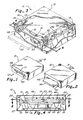
- FIG. 1 an isometric view of an optical storage disk reading apparatus constructed in accordance with the preferred embodiment of the present invention is generally identified by the reference numeral 10.
- the reading apparatus 10 comprises a storage case 12 for containing the devices to simultaneously read both sides of an optical storage disk 44 (See Fig. 7), as will be subsequently described in greater detail.
- the case 12 has an opening slot 13 for receiving an optical storage disk cartridge 46 within receiving channels 48 and 50.
- a hinged door (not shown) may be provided for closing the opening slot 13 when the apparatus 10 is not in use.
- a power and control strap 15 extends from the case 12 for connection to other appropriate devices, not shown.
- the apparatus 10 is shown with an optical storage disk cartridge 46 inserted into the case 12.
- the cartridge 46 is fixed in position relative to the case 12 by the receiving channels 48 and 50.
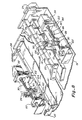
- FIG. 3 a more detailed, partially cut-away isometric view of the apparatus 10 is shown.
- the upper and lower base plates 14-16 are constructed essentially the same except that the lower base plate 16 is provided with a disk drive motor 18 and a disk drive spindle 20 (Fig. 4).
- the upper and lower base plates 14-16 are each provided with a pair of hinges 22-24 and 26-28, respectively (hinges 26 and 28 shown in Fig. 5).
- the hinges 22-28 pivotally connect the upper and lower base plates 14-16 to a frame 19 within the case 12.
- Each base plate 14-16 is matched with a lead screw 30 or 32, respectively (lead screw 32 shown in Fig. 5).
- Lead screw 30 is provided with a follower nut 34.
- lead screw 32 is provided with a follower nut 36, each of which are driven by separate stepper motors 38 and 39 (follower nut 36 and motor 39 shown in FIG. 5).
- the follower nuts 34-36 are connected to their respective base plates 14-16 by yokes 40 and 42.
- the stepper motors 38 and 39 turn the lead screws 30-32, the follower nuts 34-36 travel therealong causing the appropriate yoke 40-42 to raise or lower the attached base plates 14-16.
- the upper and lower base plates 14-16 are pivotally adjusted by their respective motors 38 and 39.
- the base plates 14-16 are pivotally adjusted until the disk 44 is the proper focal distance from optics associated with each base plate 14-16, as will be subsequently described in greater detail.
- the motors 38 and 39 are geared to allow manual rotation of the lead screws 30-32 should the need arise such as during a loss of power.
- the motors 38 and 39 are also designed to remain engaged to act as a brake to prevent unwanted movement of the base plates 14-16 once they are properly positioned.
- FIG. 4 a sectional view is shown of the apparatus 10 along the line 4-4 of Fig. 3.
- the frame 19 is separated from the case 12 by shock mounts 21.
- the drive motor 18 depends downwardly from the lower base plate 16.
- the spindle 20 protrudes through the cartridge 46 into contact with the disk hub means 63 (see Fig. 7) for rotational drive thereof.
- the hub means 63 may be held by any appropriate means, such as magnetically, and torque may be applied thereto by a pin, not shown.
- a protrusion 23 depends downwardly from the upper base plate 14 opposite the spindle 20 to prevent damage to optics associated with each plate 14- 16 by the disk 44. If the apparatus 10 were bumped hard enough to cause the disk 44 to momentarily move off the spindle 20, the protrusion 23 would prevent excessive wobble of the disk 44 by coming into contact with a hub means 63 (FIG. 7) fixed thereto.
- the hinge 22 is pinned to the frame 19 through a bracket 25 while the hinge 26 is similarly pinned through a bracket 27.
- the yoke 40 is pivotally attached to the upper base plate 14 through an extension bracket 29, as will be subsequently described in greater detail.
- the receiving channels 48 and 50 are secured to the frame 19 by means, not shown, to fix their position relative thereto.
- FIG. 5 a top plan view of the apparatus 10 is shown with the upper base plate 14 removed for the sake of clarity.
- Fixed to an upper surface 64 of the lower base plate 16 is an optical reader 54, guide rails 58 and an optical transmitter/receiver assembly generally indicated by the reference numeral 62.
- the guide rails 58 are constructed and arranged to allow the optical reader 54 to move radially with respect to the optical storage disk 44.
- the reader 54 will move radially along the rails 58 in response to a signal from a controller (not shown) to read all the data on the surface of the disk 44.
- the optical transmitter/receiver 62 is positioned at an end of the guide rails 58 opposite the spindle 20 to allow an infra-red laser 66 to direct a laser beam (not shown) at the optical reader 54.
- the laser beam is collimated by appropriate lenses such as a lens 67 and passed to a beam splitter 75.
- the beam splitter 75 has a polarizing screen 77 which deflects the laser beam toward the reader 54.
- the laser beam passes through a quarter wave plate 85 which converts the linearly polarized beam into a circularly polarized beam for use by the optical reader 54, as will be subsequently described in greater detail.
- the laser beam Upon returning from the disk 44 and the reader 54, the laser beam again passes through the wave plate 85 and is reconverted into a linearly polarized beam. Now, however, upon striking the beam splitter 75 and the polarizing screen 77, the laser beam is passed through the screen 77 due to the two quarter wave changes from the plate 85 rather than deflected therefrom. After passing through the beam splitter 75, the laser beam is deflected through a torroidal lens (not shown) and into a detector means 87.
- the detector means 87 which may include, for example, a quad detector as is well known in the art, determines whether the optical reader 54 is correctly focused on the disk 44.
- the detector means 87 will only provide data to the optical reader 54 to make focusing adjustments, as will be subsequently described, to compensate for surface irregularities on the disk 44.
- the detector means 87 also includes a photodetector, for example, such as is disclosed in U.S. patent No. 4,097,895, to Spong, June 27, 1978, capable of interpreting the data on the disk 44.
- the optical reader 54 is provided with mirror means 89 (Fig. 7) to deflect the laser beam from the laser 66 into an optical lens 70.
- the lens 70 focuses the deflected laser beam onto the reading surface of the optical storage disk 44.
- Th reader 54 moves generally perpendicular relative to upper surface 64 of the lower plate 16 about a pair of parallel flexures 72, only one of which is shown.
- the parallel flexures 72 are encircled by a wire coil 74 which may magnetically attract the flexures 72 to pull the lens 70 closer to or farther away from the optical storage disk 44.
- the optical storage disk 44 when placed upon the spindle 20, is positioned parallel to and at a fixed distance from the lower base plate 16. The fixed distance is based upon the focal distance of the lens 70 from the center position of its perpendicular travel about the flexures 72. By positioning the optical disk 44 at this distance from the lens 70, the full refocusing range of the lens 70 is available to compensate for any surface irregularities.
- the lead screw 32 provides pivotal raising and lowering motion for the lower base plate 16, and the lead screw 30 provides the same motion for the upper base plate 14.
- the lead screw 32 is driven by the stepper motor 39 and has a follower nut 36 which travels therealong.
- the lower base plate 16 is connected to the follower nut 36 by the yoke 42.
- the lead screws 30-32 are each driven independently by separate stepper motors 38 and 39 due to different dimensions of the yokes 40-42 which are necessitated by the positioning of the base plates 14 and 16 relative thereto.
- the stepper motors 38 and 39 are continuously driven to act as brakes to prevent unwanted movement of the plates 14-16 once they are properly positioned.
- FIG. 6 a sectional view taken along the line 6-6 of Fig. 5, is illustrated.
- the relationship between the optical storage disk 44, the lower base plate 16 and the upper base plate 14 may be seen more clearly.
- the optical storage disk 44 is fixed parallel to and a known distance from the lower base plate 16 through the spindle 20.
- the lower base plate 16 may pivotally move as indicated by an arrow 78, about the hinges 26 and 28 by the action of the yoke 42 and follower nut 36, the relationship between the lower base plate 16 and the disk 44 remains fixed, even though the cartridge 46 is fixed in position by the channels 48 and 50. Therefore, there must be sufficient space between the cartridge 46 and the disk 44 to allow the disk 44 to change its position relative thereto as the lower base plate 16 moves.
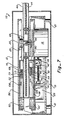
- FIG. 7 a sectional view taken along the line 7-7 of FIG. 6 is shown.
- the optical storage disk 44 contained within the cartridge 46 is slidably inserted into the reading apparatus 10 along the receiving channels 48 and 50.
- the disk 44 may be of varying thicknesses, for example, from 2.75mm to 3.50 mm.
- Optical readers 52 and 54 are slidably positioned along guide rails 56 and 58, respectively. Within each optical reader 52-54, there is a plurality of optical devices which are well known in the art to enable the optical storage disk 44 to be read, as will be subsequently described in greater detail.
- Fixed to the base plates 14-16 are optical transmitter/receivers 60 and 62, respectively, which are fixed in position relative to the optical readers 52-54. As the disk 44 is rotated about a central vertical axis, the readers 52-54 slide within the guide rails 56-58, traversing a radius of the optical storage disk 44 and reading the data thereon.
- each base plate 14-16 initiates an engagement sequence.
- the lower base plate 16 is positioned to insert the spindle 20 into a receiving hole 116 in a central disk hub means 63 which securely holds the optical storage disk 44.
- the central hub means 63 is interconnected to the disk by means not shown and rests upon drive means associated with the lower base plate 16, as will be subsequently described in greater detail.
- the storage disk 44 is thus positioned parallel to and a fixed distance from an upper surface 64 of the lower base plate 16.
- the upper base plate 14 is lowered to a predesignated position which is determined by the thickness of the thinnest storage disk available.
- the optical reader 54 for the lower base plate 16 is positioned at the proper focal length from the disk 44, but the optical reader 52 for the upper base plate 14 is likely not yet properly positioned.
- the sequence for properly positioning the upper base plate 14 to place the optical reader 52 at the proper focal distance from the disk 44 will be subsequently described in greater detail.
- the distance between the disk 44 and the lower base plate 16 is predetermined and set equal to the focal length of the lens 70 in the optical reader 54 when the lens 70 is in the center of its travel (or focusing range) about flexures 72.
- the lens 70 and the mirror means 89 may move vertically up or down relative to the disk 44 as indicated by an arrow 80 due to the coil 74.
- the coil 74 acts as a magnet to attract the metallic material of the flexures 72 thus pulling or pushing the lens 70 and the mirror means 89 farther from or closer to the disk 44 along its vertical travel 80 due to any slight distance variations therebetween.
- the distance between the disk 44 and the upper base plate 14 is also determined by a focal length of lens 71 in mirror means 69 of the optical reader 52.
- the distance from the lens 71 to the disk 44 is not preset or fixed due to a need to compensate for the various thicknesses available for optical storage disks.
- the upper base plate 14 is positioned during the engagement sequence parallel to and at a distance from the disk 44 equal to the focal length of the lens 71 to the surface of the thinnest available disk (i.e., at the closest distance therefrom).
- the optical transmitter/receiver 60 provides a signal to the stepper motor 39 (in the same fashion as previously described with respect to the receiver 62 and its detector means 87) to pivot the upper base plate 14 to a position in which the disk 44 is focused with the lens 71 and the mirror means 69 in the center of their vertical travel about parallel flexures 73.
- the lower base plate 16 is also pivoted in an opposite direction in order to maintain the parallel relationship between the upper base plate 14, the disk 44 and the lower base plate 16. Therefore, the disk 44 is positioned at the proper focal length from the upper base plate 14 and the lower base plate 16 to allow simultaneous reading of both sides thereof.
- the optical readers 52-54 move radially with respect to the disk 44 along the guide rails 56 and 58, respectively, as indicated by arrows 106 and 108. Thus, as the disk 44 is rotated about the spindle 20 by the drive motor 18, the optical readers 52-54 scan the surface of each side of the disk 44.
- the cartridge 46 has window portions therethrough to allow the lens 70-71 to be actually positioned therewithin. Since the lens 70-71 are within the cartridge 46 during the scanning or reading of the disk 44, it is necessary to ensure they are fully removed therefrom before attempting to pull the cartridge 46 from the apparatus 10. Therefor, during an unloading sequence, the base plates 14 and 16 must be pivoted sufficiently to remove the lens 70-71 from the windows in the cartridge 46. In the case of the upper base plate 14, it has been found that an upward pivoting movement of 2 degrees relative to horizontal is sufficient to remove the lens 71. However, the lower base plate 16 must be downwardly pivoted at least 5 degrees relative to horizontal in order to completely disengage the spindle 20 as well as to remove the lens 70. The cartridge 46 may then be removed and the base plates 14-16 are positioned to begin another engagement sequence upon insertion of a new cartridge. As previously described above, the protrusion 23 prevents damage to the optical readers 52-54 if the disk 44 were to wobble excessively.
- FIG. 8 a more detailed isometric view of the lead screws 30 and 32 is shown.
- the lead screws 30 and 32 are fixed by any appropriate method such as screws 122 to a portion of the frame 19 through brackets 82 and 84, respectively.
- the following discussion refers to the lead screw 32, the same description applies to the lead screw 30 with the appropriate reference number changes.
- the lead screw 32 is driven by the stepper motor 39 which is powered by a source (not shown) through the power and control strap 15 (Fig. 1).
- the follower nut 36 travels therealong as indicated by an arrow 86.
- the yoke 42 which is pivotally attached to the nut 36 by pins 88 travels therewith.
- the yoke 42 is pivotally attached to the lower base plate 16 through a bracket 110 by pin and bearing means 90.
- the pin and bearing means 90 allows the yoke 42 to have limited two-dimensional movement thereabout needed to push or pull the lower base plate 16 in what is actually an arcuate path necessitated by the cooperating arrangement of parts.
- the follower nut 36 drives the yoke 42 which in turn causes the lower base plate 16 to move generally up and down as indicated by the arrow 78.
- a pin 120 is fixed to the lower base plate 16 to protrude upwardly toward the base plate 14 as a cartridge lock.
- the different dimensions previously mentioned for the yokes 40 and 42 are more clearly shown in Fig. 8.
- the yoke 40 has a shorter connector 124 than a connector 126 on the yoke 42 due to the positioning of each lead screw 30-32 with reference to their respective base plates 14-16.
- FIGs. 9A-C, 10A-C and 11A-C the interrelationship between the base plates 14-16, the yokes 40-42 and the lead screws 30-32 is illustrated.
- the stepper motors 38 and 39 have each driven the lead screws 30-32 to place the follower nuts 34-36 at their extreme positions closest to the stepper motors 38 and 39.
- the yoke 40 is attached at a first end III to the follower nut 34 and at a second end 113 to the upper base plate 14 by a bracket 109, as the first end 111 moves in a direction indicated by an arrow 91, the second end 113 moves generally in a direction as indicated by an arrow 93.
- the upper base plate 14 is positioned in its uppermost position in which a distance G1 (defined as the distance from the storage case 12 to a bottom surface 124 of the upper base plate 14) has its greatest value.
- the yoke 42 is attached at a first end 112 to the follower nut 36 and at a second end 114 to the lower base plate 16 by the bracket 110.
- the first end 112 moves in a direction indicated by an arrow 92
- the second end 114 moves generally in a direction as indicated by an arrow 94 (opposite the direction of arrow 93).
- the lower base plate 16 is positioned in its lowermost position in which a distance H1 (defined as the distance from the storage case 12 to a bottom surface 65 of the lower base plate 16) has its smallest value. Therefore, in Fig. 10A, a distance J1 (defined as the distance between the upper base plate 14 and the lower base plate 16) has its greatest value.
- the distance J1 represents the spacing required between the plates 14 and 16 when loading and unloading the cartridge 46.
- the stepper motors 38 have turned the lead screws 30-32 to move the follower nuts 34-36 to their extreme positions distal the stepper motors 38 and 39.
- the yokes 40-42 are now in approximately vertical orientations.
- Fig. 9B it can be seen that as the first end 111 of the yoke 40 travels in a direction as indicated by an arrow 9S, the second end 113 of the yoke 40 moves generally in a direction as indicated by an arrow 97.
- the upper base plate 14 is positioned where a distance G2 has its lowest value (i.e., G2 is less than G1).
- a distance J2 has its lowest value representing the positioning immediately after the initiation sequence as previously described above with the plates 14 and 16 parallel to each other.
- the stepper motors 38 and 39 have turned the lead screws 30-32 to drive the follower nuts 34-36 to intermediate positions along the lead screws 30-32.
- the first end 111 of the yoke 40 moves in a direction indicated by an arrow 99 while the second end 113 moves generally in a direction indicated by an arrow 101. This causes the upper base plate 14 to move to a position where a distance G3 is less than G1 but greater than G2.
- the first end 112 of the yoke 42 moves in a direction indicated by arrow 100 while the second end 114 moves generally in a direction indicated by arrow 102 (opposite the direction of arrow 101).
- a distance J3 has a value less than J1, but greater than J2 representing one possible operating position.
- the upper plate 14, the lower plate 16 and the optical disk 44 are all parallel to each other for simultaneous reading of both sides of the disk 44.
- the stepper motors 38-39 drive the follower nuts 34-36 to the positions indicated in Figs. 9B and 11b in which the distances between the base plates 14-16 and the storage case 12 are equal to G2 and H2. In this closest position, the optics associated with the upper base plate 14 can then determine whether the optical storage disk 44 is in focus and make appropriate adjustments as required.
- Figs. 9C, 10C and 11C for example, appropriate adjustments have been made, positioning the upper base plate 14 at the proper distance from the optical storage disk 44 to place the optics in focus. Since the lower base plate 16 was already in focus at a fixed distance from and parallel to the optical storage disk 44, the apparatus 10 may now read both sides of optical storage disks that vary in thickness, thus cutting information transfer time in half compared with a device that reads only one side at a time.
Landscapes
- Physics & Mathematics (AREA)
- Optics & Photonics (AREA)
- Optical Recording Or Reproduction (AREA)
- Optical Head (AREA)
- Moving Of The Head For Recording And Reproducing By Optical Means (AREA)
Applications Claiming Priority (2)
| Application Number | Priority Date | Filing Date | Title |
|---|---|---|---|
| US07/432,930 US4980880A (en) | 1989-11-06 | 1989-11-06 | Method and apparatus for simultaneously reading both sides of an optical storage disk |
| US432930 | 1989-11-06 |
Publications (3)
| Publication Number | Publication Date |
|---|---|
| EP0427330A2 true EP0427330A2 (de) | 1991-05-15 |
| EP0427330A3 EP0427330A3 (en) | 1992-07-22 |
| EP0427330B1 EP0427330B1 (de) | 1995-09-06 |
Family
ID=23718146
Family Applications (1)
| Application Number | Title | Priority Date | Filing Date |
|---|---|---|---|
| EP90202907A Expired - Lifetime EP0427330B1 (de) | 1989-11-06 | 1990-11-02 | Verfahren und Vorrichtung zum gleichzeitigen Lesen beider Seiten einer optischen Speicherplatte |
Country Status (7)
| Country | Link |
|---|---|
| US (1) | US4980880A (de) |
| EP (1) | EP0427330B1 (de) |
| JP (1) | JP2911587B2 (de) |
| KR (1) | KR100219768B1 (de) |
| CA (1) | CA2029225A1 (de) |
| DE (1) | DE69022168T2 (de) |
| MX (1) | MX163864B (de) |
Cited By (4)
| Publication number | Priority date | Publication date | Assignee | Title |
|---|---|---|---|---|
| EP0579172A3 (en) * | 1992-07-13 | 1996-05-22 | Sony Corp | Disc cartridge loading device |
| US5623457A (en) * | 1993-04-12 | 1997-04-22 | Sony Corporation | Photomagnetic disc drive system having a locking mechanism |
| US5815470A (en) * | 1994-08-11 | 1998-09-29 | Sony Corporation | Disc drive unit |
| EP0944067A3 (de) * | 1998-03-19 | 2000-01-05 | Pioneer Electronic Corporation | Plattenspieler |
Families Citing this family (2)
| Publication number | Priority date | Publication date | Assignee | Title |
|---|---|---|---|---|
| RU2162253C1 (ru) * | 2000-06-26 | 2001-01-20 | Закрытое акционерное общество "Инфокристал" | Способ автофокусировки оптического излучения на информационном слое носителя информации и устройство для его осуществления |
| RU2187153C2 (ru) * | 2000-10-10 | 2002-08-10 | Общество С Ограниченной Ответственностью "Инсмат Технология" | Способ слежения за информационной дорожкой дискового носителя оптической записи и дисковый носитель для его осуществления |
Family Cites Families (16)
| Publication number | Priority date | Publication date | Assignee | Title |
|---|---|---|---|---|
| US3079839A (en) * | 1959-06-22 | 1963-03-05 | Erwin E Lohner | Duplex photocopier |
| US4097895A (en) * | 1976-03-19 | 1978-06-27 | Rca Corporation | Multilayer optical record |
| GB1577132A (en) * | 1976-03-19 | 1980-10-22 | Rca Corp | Compensation apparatus for a servo system with periodic command signals |
| US4125324A (en) * | 1976-07-02 | 1978-11-14 | Spence Bate | Copying apparatus |
| US4189233A (en) * | 1977-03-07 | 1980-02-19 | Westinghouse Electric Corp. | Passive optical range simulator device |
| US4271489A (en) * | 1979-05-23 | 1981-06-02 | Rca Corporation | Optical disc player system |
| US4286790A (en) * | 1979-05-23 | 1981-09-01 | Rca Corporation | Optical disc changer apparatus |
| FR2458126A1 (fr) * | 1979-05-31 | 1980-12-26 | Thomson Brandt | Systeme de commande de changement de face lue pour un lecteur optique de support d'information et lecteur optique comportant un tel systeme |
| FR2474221A1 (fr) * | 1980-01-23 | 1981-07-24 | Thomson Csf | Dispositif optique d'enregistrement-lecture de supports d'information et systeme de memoire optique comportant un tel systeme |
| JPS5850336A (ja) * | 1981-09-17 | 1983-03-24 | Matsushita Electric Ind Co Ltd | 可動体保持装置 |
| NL8500592A (nl) * | 1985-03-04 | 1986-10-01 | Philips Nv | Electro-optische inrichting. |
| FR2583533B1 (fr) * | 1985-06-12 | 1988-11-04 | Cuvillier Roger | Appareil photographique pour prise de vues stereoscopiques. |
| GB8702130D0 (en) * | 1987-01-30 | 1987-03-04 | Sira Ltd | Surface inspection |
| US4748456A (en) * | 1987-02-24 | 1988-05-31 | Luoma E Thomas | Photoplotter focus method |
| NL8703009A (nl) * | 1987-12-14 | 1989-07-03 | Philips Nv | Apparaat voor het afspelen van een roterend aandrijfbare plaat. |
| JPH01199323A (ja) * | 1988-02-03 | 1989-08-10 | Toshiba Corp | 情報処理装置 |
-
1989
- 1989-11-06 US US07/432,930 patent/US4980880A/en not_active Expired - Lifetime
-
1990
- 1990-10-31 MX MX23150A patent/MX163864B/es unknown
- 1990-11-02 DE DE69022168T patent/DE69022168T2/de not_active Expired - Fee Related
- 1990-11-02 CA CA002029225A patent/CA2029225A1/en not_active Abandoned
- 1990-11-02 EP EP90202907A patent/EP0427330B1/de not_active Expired - Lifetime
- 1990-11-06 JP JP2299083A patent/JP2911587B2/ja not_active Expired - Lifetime
- 1990-11-06 KR KR1019900017862A patent/KR100219768B1/ko not_active Expired - Fee Related
Cited By (5)
| Publication number | Priority date | Publication date | Assignee | Title |
|---|---|---|---|---|
| EP0579172A3 (en) * | 1992-07-13 | 1996-05-22 | Sony Corp | Disc cartridge loading device |
| US5623457A (en) * | 1993-04-12 | 1997-04-22 | Sony Corporation | Photomagnetic disc drive system having a locking mechanism |
| US5815470A (en) * | 1994-08-11 | 1998-09-29 | Sony Corporation | Disc drive unit |
| US5841752A (en) * | 1994-08-11 | 1998-11-24 | Sony Corporation | Disc drive unit |
| EP0944067A3 (de) * | 1998-03-19 | 2000-01-05 | Pioneer Electronic Corporation | Plattenspieler |
Also Published As
| Publication number | Publication date |
|---|---|
| DE69022168T2 (de) | 1996-04-18 |
| KR100219768B1 (ko) | 1999-09-01 |
| CA2029225A1 (en) | 1991-05-07 |
| EP0427330A3 (en) | 1992-07-22 |
| US4980880A (en) | 1990-12-25 |
| DE69022168D1 (de) | 1995-10-12 |
| JP2911587B2 (ja) | 1999-06-23 |
| MX163864B (es) | 1992-06-26 |
| EP0427330B1 (de) | 1995-09-06 |
| KR910010423A (ko) | 1991-06-29 |
| JPH03171435A (ja) | 1991-07-24 |
Similar Documents
| Publication | Publication Date | Title |
|---|---|---|
| RU2056647C1 (ru) | Устройство для записи и/или воспроизведения с оптического диска | |
| US5970041A (en) | Disc changer device increasing the distance between a gripped disc and neighboring discs on both sides of the gripped disc | |
| US6667945B2 (en) | Disk drive device | |
| JP3059417B2 (ja) | 電子光学装置 | |
| US6175544B1 (en) | Disc recording and/or reproducing apparatus | |
| US5521899A (en) | Optical disk apparatus for mechanically restricting the distance between an optical disk and an optical head | |
| EP0427330B1 (de) | Verfahren und Vorrichtung zum gleichzeitigen Lesen beider Seiten einer optischen Speicherplatte | |
| EP0519069B1 (de) | Automatischer plattenwechsler | |
| US7301872B2 (en) | Optical pickup and optical disc drive device | |
| JP3428030B2 (ja) | ディスク記録及び/又は再生装置 | |
| US20020071357A1 (en) | Optical pick-up device | |
| EP1422699B1 (de) | Verfahren zur einstellung der neigung einer führungswelle in einer aufzeichnungsmediumsansteuereinrichtung | |
| JP2944379B2 (ja) | 光ディスクプレーヤ | |
| JP3572771B2 (ja) | 光磁気ディスク装置 | |
| JP3031007B2 (ja) | ディスクカートリッジ | |
| KR0161937B1 (ko) | 광 디스크 플레이어 | |
| KR100297773B1 (ko) | 대물렌즈 경사조정장치 | |
| JPH07169166A (ja) | 情報処理装置 | |
| JPH0224868A (ja) | 情報記録装置 | |
| JPH097204A (ja) | 情報蓄積装置の対物レンズ支持装置 | |
| JPH11110760A (ja) | 光学ピックアップ装置におけるスキュー調整方法 | |
| JP2003141791A (ja) | 光磁気記録再生装置 | |
| JPH05151599A (ja) | 光ヘツド装置 | |
| JPH05182236A (ja) | 光ディスクドライブ装置 | |
| JP2001060322A (ja) | ピックアップを具えたディスクへの信号記録又は再生装置及び該ピックアップ |
Legal Events
| Date | Code | Title | Description |
|---|---|---|---|
| PUAI | Public reference made under article 153(3) epc to a published international application that has entered the european phase |
Free format text: ORIGINAL CODE: 0009012 |
|
| AK | Designated contracting states |
Kind code of ref document: A2 Designated state(s): DE FR GB IT |
|
| PUAL | Search report despatched |
Free format text: ORIGINAL CODE: 0009013 |
|
| RAP1 | Party data changed (applicant data changed or rights of an application transferred) |
Owner name: N.V. PHILIPS' GLOEILAMPENFABRIEKEN |
|
| AK | Designated contracting states |
Kind code of ref document: A3 Designated state(s): DE FR GB IT |
|
| 17P | Request for examination filed |
Effective date: 19930112 |
|
| 17Q | First examination report despatched |
Effective date: 19940323 |
|
| GRAA | (expected) grant |
Free format text: ORIGINAL CODE: 0009210 |
|
| AK | Designated contracting states |
Kind code of ref document: B1 Designated state(s): DE FR GB IT |
|
| REF | Corresponds to: |
Ref document number: 69022168 Country of ref document: DE Date of ref document: 19951012 |
|
| ITF | It: translation for a ep patent filed | ||
| ET | Fr: translation filed | ||
| PLBE | No opposition filed within time limit |
Free format text: ORIGINAL CODE: 0009261 |
|
| STAA | Information on the status of an ep patent application or granted ep patent |
Free format text: STATUS: NO OPPOSITION FILED WITHIN TIME LIMIT |
|
| 26N | No opposition filed | ||
| REG | Reference to a national code |
Ref country code: FR Ref legal event code: CD |
|
| REG | Reference to a national code |
Ref country code: GB Ref legal event code: 732E |
|
| REG | Reference to a national code |
Ref country code: FR Ref legal event code: TP |
|
| REG | Reference to a national code |
Ref country code: GB Ref legal event code: IF02 |
|
| PGFP | Annual fee paid to national office [announced via postgrant information from national office to epo] |
Ref country code: GB Payment date: 20021022 Year of fee payment: 13 |
|
| PGFP | Annual fee paid to national office [announced via postgrant information from national office to epo] |
Ref country code: FR Payment date: 20021118 Year of fee payment: 13 |
|
| PGFP | Annual fee paid to national office [announced via postgrant information from national office to epo] |
Ref country code: DE Payment date: 20021129 Year of fee payment: 13 |
|
| PG25 | Lapsed in a contracting state [announced via postgrant information from national office to epo] |
Ref country code: GB Free format text: LAPSE BECAUSE OF NON-PAYMENT OF DUE FEES Effective date: 20031102 |
|
| PG25 | Lapsed in a contracting state [announced via postgrant information from national office to epo] |
Ref country code: DE Free format text: LAPSE BECAUSE OF NON-PAYMENT OF DUE FEES Effective date: 20040602 |
|
| GBPC | Gb: european patent ceased through non-payment of renewal fee |
Effective date: 20031102 |
|
| PG25 | Lapsed in a contracting state [announced via postgrant information from national office to epo] |
Ref country code: FR Free format text: LAPSE BECAUSE OF NON-PAYMENT OF DUE FEES Effective date: 20040730 |
|
| REG | Reference to a national code |
Ref country code: FR Ref legal event code: ST |
|
| PG25 | Lapsed in a contracting state [announced via postgrant information from national office to epo] |
Ref country code: IT Free format text: LAPSE BECAUSE OF NON-PAYMENT OF DUE FEES Effective date: 20051102 |