EP0427403A2 - Dispositif de mouillage pour la lithographie - Google Patents
Dispositif de mouillage pour la lithographie Download PDFInfo
- Publication number
- EP0427403A2 EP0427403A2 EP90311200A EP90311200A EP0427403A2 EP 0427403 A2 EP0427403 A2 EP 0427403A2 EP 90311200 A EP90311200 A EP 90311200A EP 90311200 A EP90311200 A EP 90311200A EP 0427403 A2 EP0427403 A2 EP 0427403A2
- Authority
- EP
- European Patent Office
- Prior art keywords
- roller
- dampener
- metering
- form roller
- metering roller
- Prior art date
- Legal status (The legal status is an assumption and is not a legal conclusion. Google has not performed a legal analysis and makes no representation as to the accuracy of the status listed.)
- Withdrawn
Links
- 239000007788 liquid Substances 0.000 claims abstract description 61
- 230000033001 locomotion Effects 0.000 claims description 5
- 230000007246 mechanism Effects 0.000 claims description 4
- 239000000839 emulsion Substances 0.000 abstract description 3
- 238000010276 construction Methods 0.000 description 4
- 239000000203 mixture Substances 0.000 description 3
- 230000009471 action Effects 0.000 description 2
- 239000000463 material Substances 0.000 description 2
- 229920002799 BoPET Polymers 0.000 description 1
- 239000005041 Mylar™ Substances 0.000 description 1
- 230000005540 biological transmission Effects 0.000 description 1
- 230000008859 change Effects 0.000 description 1
- 238000009434 installation Methods 0.000 description 1
- 230000005923 long-lasting effect Effects 0.000 description 1
- 238000005461 lubrication Methods 0.000 description 1
- 230000002093 peripheral effect Effects 0.000 description 1
- 230000003252 repetitive effect Effects 0.000 description 1
- 238000007789 sealing Methods 0.000 description 1
- 238000004513 sizing Methods 0.000 description 1
- 230000007480 spreading Effects 0.000 description 1
Images


Classifications
-
- B—PERFORMING OPERATIONS; TRANSPORTING
- B41—PRINTING; LINING MACHINES; TYPEWRITERS; STAMPS
- B41F—PRINTING MACHINES OR PRESSES
- B41F7/00—Rotary lithographic machines
- B41F7/20—Details
- B41F7/24—Damping devices
- B41F7/26—Damping devices using transfer rollers
Definitions
- This invention relates to improvements in lithographic dampeners, and particularly to the type of dampener described in US Patent No. 4,455,938 in which a dampening liquid is applied through a form roller, which is continually contacting a plate on the press, by a metering roller which is continually in contact with the form roller and the source of dampening liquid.
- a small reservoir of dampening liquid is formed in the nip above and between the form roller and metering roller, and the action of the two rollers is such as to mix or mill the ink and dampening liquid together to form an emulsion, which results in quick and uniform inking of the image areas of the plate and dampening of non-image areas.
- the ends of such nip are, in some embodiments, closed by seals which run tightly against the peripheral surface of the metering roller at its ends and against the end faces of the form roller.
- the metering roller carries dampening liquid to the nip from a pan, no seal is provided, and excess liquid at the nip flows outward and downward along the metering roller, which is longer than the form roller, returning to the pan.
- those embodiments are somewhat disadvantageous, particularly at higher press speeds, since the friction from the tight seals increases with roller speed, as does seal wear. Further, if the press be operated at considerably different speeds, particularly if it is necessary to tighten the metering/form rollers' nip at higher operating speeds, the seals may leak as a result of their movement which is a consequence of increasing the nip pressure by moving the metering roller tighter against the form roller.
- the present invention provides an improved lithographic dampener in which the metering roller surface, in addition to being pressed against the resilient form roller surface, extends into a supply pool of dampening liquid which is maintained in a shallow pan at a controlled level.
- the pan extends under and beyond the metering/form rollers' nip, and in a rearward direction extends substantially beyond the rear or back plate of the dampener structure.
- An oscillator roller runs in contact with the metering roller, and functions to spread or smear the ink/liquid mixture on the metering roller surface, before the mixture is carried over the top of the metering roller into the nip. At the same time, the oscillator roller is pressed against the metering roller and performs the additional function of metering the amount of additional dampening liquid carried to the nip from the pool.
- the dampener structure includes side members which are connected at their front (closest to the press plate cylinder) by rigid tie rods. At the other or rear ends of the side members, there is a backplate (or endcap) joining them, and the pan for dampening liquid supply is attached to the bottom of the side members.
- a remote supply bottle is joined to a height adjustable level maintaining valve at the pan, so as to keep a constant preselectable level of liquid available to the metering roller.
- Each side member has a slide track extending forward from the endcap toward the tie rods, and including a vertically enlarged rearward section.
- Slide blocks are received in the respective tracks and have inwardly facing bosses supporting the end bearings of the metering roller.
- Springs act between the side members and slide blocks, urging the blocks toward the endcap, and at each rear corner there are adjustment screws which press against the slide blocks, urging them forward against the springs and thus setting the pressure of the metering roller against the form roller.
- a form roller drive gear is fixed to the form roller shaft and meshes with the plate cylinder gear of the press when the dampener is in operative position, to cause counter rotation of the form roll and plate cylinder.
- rigid form roller, metering roller, and oscillating roller constructions are employed which can be lengthened along with the tie rods and endcap while achieving the needed rigidity.
- this design uses simple plate-like flexible end seals which are pressed against the ends of the metering and form rollers (which are of the same length). These seal plates form end dams which allow some leakage of liquid between them and the roller ends. This leakage provides some lubrication between the stationary seal plates and the rotating roller ends, deflects any liquid which may flow rapidly toward the ends of the nip into the pan, and controls the level of the reservoir of liquid in the nip by providing an overflow exit at least at one end. Since there is low friction in this arrangement, it is long lasting and effective over a range of roller speeds.
- the open front dampener frame construction permits the form roller to contact a printing plate (on the plate cylinder) over a substantial range of locations around the plate cylinder periphery. This simplifies mounting of the dampener to different press configurations, thus the design has retrofit advantages.
- the metering/form rollers' nip location can be varied considerably, as by a change in side member shape and dimensions, so long as there is enough volume above that nip and between the seal plates.
- Two forms of mounting support are provided for this unique dampener structure.
- slotted brackets are attached to the outer parts of the dampener side members, and the slots in these brackets are engaged with bushing fitted to the press side frames.
- a supporting shaft extends through the bearings of the form roller and outward through the dampener side members, into bushings (or equivalent) fitted to the press side members.
- a "drawer-like" arrangement which is easy to mount for motion toward and away from the plate cylinder.
- the dampener side members have pairs of rollers which can be supported in slides fitted to the interior of the press side frames. This allows the dampener to be inserted into such slides and precisely located between the press side frames to achieve the desired fitting of the form roller to the surface of the press plate cylinder.
- the form roller is gear driven from the plate cylinder gear (which in turn is coupled to the press drive). In small sizes, this is adequate to accommodate disengaging motion of the dampener mechanism, as may be desired in makeready or other non-printing press function. However, in larger sizes, as for commercial multi-color presses, it is desirable to drive the metering roller through a gear drive, and to throw-off the dampener by a motion which centers around the metering roller axis and its drive. This may be desired also from the standpoint that larger presses may use helical gears for increased power transmission, and it is not practical to partially disengage a helical gear train.
- the primary object of this invention is to provide an improved lithographic dampener of the type having continuous plate/form roller/metering roller contact, in which the dampener is adaptable to a variety of press configurations and operating speeds; to provide such a dampener which also employs a friction-driven oscillator roller that distributes added dampening liquid and the ink/liquid emulsions on the metering roller, to avoid continuing patterns which might cause ghosting in printed images; to provide such a dampener with a pan with a remote supply of dampening liquid, located under the rollers such that the metering roller surface contacts a picks up liquid from a pool in the pan, and wherein the oscillator roller acts to meter the amount of liquid thus applied to the metering roller surface; to provide such a dampener having a simple drawer-like configuration, with an open front for improved range of form roller/plate contact; to provide novel mounting arrangements for such a drawer-like dampener structure; to provide such a press with simplified seal dams at the ends
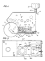
- Fig. 1 shows a dampener built according to the present invention, fitted to a commercially available second color adapter unit, which in turn is intended to be fitted to a small offset lithographic press. It should be understood that the dampener can be installed directly on an offset lithographic press, and that the unit illustrated is intended merely to show one form of typical installation.
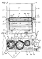
- the adapter unit includes side frame members 10A and 10B (Figs. 1 and 2) which are typical of such press construction, supporting a plate cylinder 14 and its drive gear 15.
- the circles above the plate cylinder in Fig. 1 represent rollers of an inking train, which form no part of the invention.
- Other press structure is omitted for simplification, since it does not form part of the invention, and is generally known.
- the dampener comprises a pair of side members 20A and 20B connected by tie rods 21 and 22, and by a rear plate or endcap 25.
- Each side member has a slide track opening 26A and 26B extending forward from the endcap toward the tie rods, and including a vertically enlarged rearward section 27A and 27B.
- bearings 30A and 30B which support opposite ends of stub shafts 32A and 32B which extend from fittings 33A and 33B in the ends of the tubular interior of the form roller 35.
- a form roller drive gear 36 is attached to stub shaft 32B, and meshes with the plate cylinder gear 15 when the dampener is in operative position, to cause positive counter rotation of the form roller 35 and plate cylinder.
- a locating and supporting shaft 37 extends through the interior of the form roller, inside needle bearings 38A and 38B within fittings 33A and 33B, and shaft 37 is received into plug-like bushings fitted into the side frames 10A, 10B, to align the form roller (and the rest of the dampener structure) with the plate cylinder and the gears, and to support the inner or forward part of the dampener structure (around form roller 14) between the press side frame members.
- a shallow dampener pan 40 which has brackets 42A and 42B extending along an attached to the bottom of the pan, and at the dampener front attached to the endcap 25 by thumbscrews 43. As shown in Figs. 3 and 4, the pan extends forward under the form roller 35, and rearward beyond endcap 25.
- the metering roller 45 is supported in bearings 46A and 46B at its opposite ends, with the metering roller surface normally engaging the surface of form roller 35, and with the lower portion of the metering roller surface extending into a pool of dampening liquid in pan 40, as shown in Fig. 4.
- Bearings 46A and 46B are carried in slide blocks 50A and 50B which are received in the respective track openings, and which have inwardly facing bosses 52A and 52B receiving the outer races of these bearings.
- Coil springs 53 extend from bores 54 in the side members, facing toward the slide blocks and urging them toward endcap 25. At each rear corner, threaded into endcap 25, are forward facing adjustment screws 55 which press against slide blocks 50A and 50B, urging them forward against springs 53, and thus setting the pressure of metering roller 45 against form roller 35.
- the rollers 35 and 45 are comparable to the form roller and metering roller as described in said US patent No. 4,455,938, and act to mix or mill the dampening liquid/ink mixture on the roller surfaces.
- the surface 35A of form roller 35 is formed of a suitable rubber-like material, and is more soft or resilient than the surface 45A of the metering roller.
- screws 55 may be operator adjusted to produce a desired pressure at the form roller/metering roller nip and this will result in some deformation of the form roller surface 35A at such nip. If the region above the dampener structure is to be open to operator access during operation (in the embodiment shown that nip is under other press structure) a cover may be added over the dampener rollers.
- Slide blocks 50A and 50B also have horizontally elongated slot-like apertures 60A, 60B in their enlarged rearward portions, receiving smaller slide blocks 62A and 62B that carry the ends of a shaft 64 which supports an oscillator roller 65.
- the ends of shaft 64 are fixed to blocks 62A and 62B, so the shaft does not rotate.
- Adjusting screws 66 are threaded through the rear ends of slide blocks 50A and 50B and extend into contact with the slide blocks 62A and 62B. Access to screws 66 is provided through bores 67 in endcap 25.
- Shaft 64 has sleeve bearings 68 at its opposite ends, supporting the inner tube 70 of the roller, which in turn carries the outer roller sleeve 72.
- One sleeve bearing 68 is elongated, and holds a follower button 74 therein, which button engages a reversing helical track 75 formed in shaft 64.
- button 74 moves along track 75, causing a side-to-side excursion of oscillator roller 65 in a known manner. This produces a spreading action of the mixed ink and dampening liquid on the metering roller surface 45A, at the region where additional dampening liquid has been picked up by that surface from the pool in pan 40.
- Outer end support brackets 77 are secured to the outside of the dampener side members 20A and 20B, as shown in Fig. 10. Slots 78 in brackets 77 fit around flats formed on support bushings 79, which are in turn fitted into the press side frame members 10a, 10B. To mount the dampener, the unit is brought upward and forward to engage brackets 77 to bushings 79, then the dampener structure is swung upward to align the form roller center with the apertures in the press side frames, and the shaft 37 is inserted and secured.
- the pressure setting of metering roller 45 against form roller 35 is achieved by adjusting screws 55, and pressure of oscillator roller 65 against metering roller 45 is achieved independently by adjusting screws 66. Additional dampening liquid is carried from pan 40 into the nip between rollers 35 and 45.
- Dampening liquid is replenished in pan 40 from a remote supply bottle 80 (Fig. 1) through a control valve 82 (see also Fig. 5).
- This valve has a valve head 82A which is normally seated by pressure of spring 82B. When a bottle is properly in place thereon, its neck thrusts on the upper end 82C of the valve head and opens the valve so long as a bottle is in place.
- Valve 82 is connected via a flexible tube 83 to a further control valve 85 (see also Fig. 6), which has a valve head 85A urged toward a seat 85B by spring 85C.
- the housing 86 of valve 85 is fitted into a socket 87 which is in turn supported from a bracket 88 which is vertically adjustably mounted to endcap 25.
- Socket 87 leaves the lower edge 85D open to communicate with the interior of pan 40.
- Valve stem 85E will engage the bottom of socket 87, and open the valve, and the entire valve assembly can be vertically adjusted relative to pan 40, by turning thumbscrew 89. In this fashion, the height of liquid in pan 40 is determined by the height adjustment of the lower edge of the valve body, relative to the bottom of pan 40.
- nip region between form roller 35 and metering roller 45 is shown on an enlarged scale, and one of the end dam seal plates 90 is illustrated, fitted against the outer ends of those rollers.
- This plate is formed from a thin flexible material, such as Mylar, and has a rounded forward edge 92 which generally conforms to the contour of form roller 35.
- a central hole (not shown) in the seal plate fits around the form roller shaft, and a further hole 93 fits around tie rod 22, thus holding the plate against rotation.
- a suitable spring 95 (shown schematically in Fig. 9) presses the plate against the ends of the rollers, it being understood that these ends are in the same vertical plane since the rollers are of the same length.
- the spring pressure is sufficient to keep the seal plate 90 seated, but not to prevent some leakage of liquid between the plate and the ends of the rollers, returning to pan 40 which extends under the nip (see Figs. 1 and 4).
- An overflow hole 96 in at least one of the seal plates allows excess build up of liquid in the nip reservoir to pass and drop directly into pan 40, thus establishing the maximum capacity of the liquid pool in that nip.
- roller bearings 100A and 100B are mounted to the outsides of the dampener side members.
- Track members 104A and 104B are secured to the interior side of press side frame members 10A, 10B.
- Each track member has formed, on its inside surface facing the dampener, a cooperating pair of generally inverted L-shaped tracks 105. These tracks terminate in locating sockets 106, and are designed to receive the roller bearings 100A, 100B, and to guide these in and out of the sockets.
- the dampener has a generally draw-like design which allows it to be rolled in and downs to its operative position, and to be lifted and withdrawn for servicing.
Landscapes
- Engineering & Computer Science (AREA)
- Mechanical Engineering (AREA)
- Rotary Presses (AREA)
- Inking, Control Or Cleaning Of Printing Machines (AREA)
Applications Claiming Priority (2)
| Application Number | Priority Date | Filing Date | Title |
|---|---|---|---|
| US42020189A | 1989-10-12 | 1989-10-12 | |
| US420201 | 1989-10-12 |
Publications (2)
| Publication Number | Publication Date |
|---|---|
| EP0427403A2 true EP0427403A2 (fr) | 1991-05-15 |
| EP0427403A3 EP0427403A3 (en) | 1991-11-13 |
Family
ID=23665492
Family Applications (1)
| Application Number | Title | Priority Date | Filing Date |
|---|---|---|---|
| EP19900311200 Withdrawn EP0427403A3 (en) | 1989-10-12 | 1990-10-12 | Lithographic dampener |
Country Status (3)
| Country | Link |
|---|---|
| US (1) | US5134935A (fr) |
| EP (1) | EP0427403A3 (fr) |
| CA (1) | CA2027401C (fr) |
Cited By (2)
| Publication number | Priority date | Publication date | Assignee | Title |
|---|---|---|---|---|
| DE19722076A1 (de) * | 1996-06-06 | 1998-01-08 | Ryobi Ltd | Befeuchtungsvorrichtung für eine Druckmaschine |
| US6092938A (en) * | 1997-10-09 | 2000-07-25 | Eastman Kodak Company | Processing photographic material |
Families Citing this family (4)
| Publication number | Priority date | Publication date | Assignee | Title |
|---|---|---|---|---|
| US5265535A (en) * | 1991-12-28 | 1993-11-30 | Kabushiki Kaisha Isowa | Printing machine for corrugated board sheet |
| WO1994019190A1 (fr) * | 1993-02-22 | 1994-09-01 | Keller James J | Systeme mouilleur a reception d'encre pour presse d'impression lithographique |
| US5865116A (en) * | 1993-02-22 | 1999-02-02 | Keller; James J. | Ink receptive dampening system for lithographic printing press |
| US5680816A (en) * | 1996-09-27 | 1997-10-28 | Varn Products Company, Inc. | Live shaft oscillator for lithographic press dampener |
Family Cites Families (11)
| Publication number | Priority date | Publication date | Assignee | Title |
|---|---|---|---|---|
| US3283707A (en) * | 1964-03-25 | 1966-11-08 | Interchem Corp | Apparatus for applying fountain solution in planographic printing |
| US3283741A (en) * | 1964-05-01 | 1966-11-08 | John C Motter Printing Press C | Coating apparatus |
| US3343484A (en) * | 1964-12-16 | 1967-09-26 | Harold P Dahlgren | Lithographic dampener with skewed metering roller |
| DE1906056C3 (de) * | 1968-02-23 | 1974-03-07 | Adamovske Strojirny, N.P., Adamov (Tschechoslowakei) | Vorrichtung zum An- und Abstellen der Auftragwalzen eines Feuchtwerks für eine Rotationsoffsetdruckmaschine |
| US3769909A (en) * | 1971-03-10 | 1973-11-06 | Rockwell International Corp | Wet nip dampener |
| US4455938A (en) * | 1979-05-22 | 1984-06-26 | Graph Tech Inc. | Dampening apparatus for lithographic press |
| DE3116505C2 (de) * | 1981-04-25 | 1985-03-28 | M.A.N.- Roland Druckmaschinen AG, 6050 Offenbach | Rotationsdruckmaschine, die wahlweise für verschiedene Druckverfahren verwendbar ist |
| KR870013854A (ko) * | 1983-05-25 | 1987-09-11 | 쥬우가이토 고오교오 가부시기가이샤 | 코우팅기의 사용에서 코우팅량을 자동적으로 조절하는 장치 |
| US4841855A (en) * | 1984-10-11 | 1989-06-27 | Marcum Charles L | Dampening unit for printing press |
| EP0296394B1 (fr) * | 1987-06-25 | 1992-03-04 | Heidelberger Druckmaschinen Aktiengesellschaft | Dispositif de mouillage pour une machine à imprimer en offset |
| DE8915545U1 (de) * | 1989-05-03 | 1990-08-30 | Heidelberger Druckmaschinen Ag, 6900 Heidelberg | Dichtungsanordnung |
-
1990
- 1990-10-03 US US07/592,150 patent/US5134935A/en not_active Expired - Lifetime
- 1990-10-11 CA CA002027401A patent/CA2027401C/fr not_active Expired - Fee Related
- 1990-10-12 EP EP19900311200 patent/EP0427403A3/en not_active Withdrawn
Cited By (3)
| Publication number | Priority date | Publication date | Assignee | Title |
|---|---|---|---|---|
| DE19722076A1 (de) * | 1996-06-06 | 1998-01-08 | Ryobi Ltd | Befeuchtungsvorrichtung für eine Druckmaschine |
| DE19722076C2 (de) * | 1996-06-06 | 2000-01-13 | Ryobi Ltd | Feuchtwerk für eine Druckmaschine |
| US6092938A (en) * | 1997-10-09 | 2000-07-25 | Eastman Kodak Company | Processing photographic material |
Also Published As
| Publication number | Publication date |
|---|---|
| CA2027401C (fr) | 1995-02-14 |
| US5134935A (en) | 1992-08-04 |
| CA2027401A1 (fr) | 1991-04-13 |
| EP0427403A3 (en) | 1991-11-13 |
Similar Documents
| Publication | Publication Date | Title |
|---|---|---|
| US4455938A (en) | Dampening apparatus for lithographic press | |
| US4972771A (en) | Film dampener unit for offset printing presses | |
| JPH0326127B2 (fr) | ||
| US5505126A (en) | Dampening arrangement for a printing press | |
| US5134935A (en) | Lithograhic dampener | |
| US5088402A (en) | Pressurized printing fluid input system for keyless lithographic printing | |
| EP0583667A1 (fr) | Appareil d'impression | |
| JP2574330Y2 (ja) | オフセット印刷機用の湿し装置 | |
| JPH1044377A (ja) | 印刷機用のインキ装置 | |
| JP4652517B2 (ja) | 平版印刷機の湿し装置、および、この湿し装置を有する平版印刷機 | |
| US5865116A (en) | Ink receptive dampening system for lithographic printing press | |
| US5357856A (en) | Squeege device for supplying ink in a stencil printing device | |
| SU1043037A1 (ru) | Увлажн ющий аппарат дл ротационных печатных машин | |
| US4538514A (en) | Inking or damping unit for rotary printing machines | |
| US4739703A (en) | Inking apparatus for printing press with vibrating form roller | |
| EP0476328B1 (fr) | Système amélioré d'impression sans clés pour l'impression lithographique sans clés d'encrage | |
| US6782819B2 (en) | Inking apparatus and side plate thereof | |
| US5540145A (en) | Ink receptive dampening system for lithographic printing press | |
| US5878663A (en) | Dampener recirculator apparatus for a printing press | |
| EP0313702B1 (fr) | Dispositif d'encrage pour machine à imprimer | |
| AU2003300331A1 (en) | Dampener metering device | |
| US4729307A (en) | Form roller attachment for lithographic press | |
| US5680816A (en) | Live shaft oscillator for lithographic press dampener | |
| JP2778938B2 (ja) | ノズル式ダンプニング装置のノズル移動制御装置 | |
| EP0345716A2 (fr) | Dispositif de mouillage pour presse lithographique |
Legal Events
| Date | Code | Title | Description |
|---|---|---|---|
| PUAI | Public reference made under article 153(3) epc to a published international application that has entered the european phase |
Free format text: ORIGINAL CODE: 0009012 |
|
| AK | Designated contracting states |
Kind code of ref document: A2 Designated state(s): BE DE FR GB IT |
|
| PUAL | Search report despatched |
Free format text: ORIGINAL CODE: 0009013 |
|
| AK | Designated contracting states |
Kind code of ref document: A3 Designated state(s): BE DE FR GB IT |
|
| 17P | Request for examination filed |
Effective date: 19920109 |
|
| 17Q | First examination report despatched |
Effective date: 19931124 |
|
| STAA | Information on the status of an ep patent application or granted ep patent |
Free format text: STATUS: THE APPLICATION IS DEEMED TO BE WITHDRAWN |
|
| 18D | Application deemed to be withdrawn |
Effective date: 19951010 |