EP0427560A2 - Entfernung eines Mehrstiftskomponenten, der in Buchsen auf einer Schaltungsplatte montiert ist - Google Patents
Entfernung eines Mehrstiftskomponenten, der in Buchsen auf einer Schaltungsplatte montiert ist Download PDFInfo
- Publication number
- EP0427560A2 EP0427560A2 EP90312280A EP90312280A EP0427560A2 EP 0427560 A2 EP0427560 A2 EP 0427560A2 EP 90312280 A EP90312280 A EP 90312280A EP 90312280 A EP90312280 A EP 90312280A EP 0427560 A2 EP0427560 A2 EP 0427560A2
- Authority
- EP
- European Patent Office
- Prior art keywords
- post
- screw
- circuit board
- sockets
- further characterised
- Prior art date
- Legal status (The legal status is an assumption and is not a legal conclusion. Google has not performed a legal analysis and makes no representation as to the accuracy of the status listed.)
- Withdrawn
Links
Images


Classifications
-
- H—ELECTRICITY
- H01—ELECTRIC ELEMENTS
- H01R—ELECTRICALLY-CONDUCTIVE CONNECTIONS; STRUCTURAL ASSOCIATIONS OF A PLURALITY OF MUTUALLY-INSULATED ELECTRICAL CONNECTING ELEMENTS; COUPLING DEVICES; CURRENT COLLECTORS
- H01R13/00—Details of coupling devices of the kinds covered by groups H01R12/70 or H01R24/00 - H01R33/00
- H01R13/62—Means for facilitating engagement or disengagement of coupling parts or for holding them in engagement
- H01R13/629—Additional means for facilitating engagement or disengagement of coupling parts, e.g. aligning or guiding means, levers, gas pressure electrical locking indicators, manufacturing tolerances
- H01R13/633—Additional means for facilitating engagement or disengagement of coupling parts, e.g. aligning or guiding means, levers, gas pressure electrical locking indicators, manufacturing tolerances for disengagement only
-
- Y—GENERAL TAGGING OF NEW TECHNOLOGICAL DEVELOPMENTS; GENERAL TAGGING OF CROSS-SECTIONAL TECHNOLOGIES SPANNING OVER SEVERAL SECTIONS OF THE IPC; TECHNICAL SUBJECTS COVERED BY FORMER USPC CROSS-REFERENCE ART COLLECTIONS [XRACs] AND DIGESTS
- Y10—TECHNICAL SUBJECTS COVERED BY FORMER USPC
- Y10T—TECHNICAL SUBJECTS COVERED BY FORMER US CLASSIFICATION
- Y10T29/00—Metal working
- Y10T29/49—Method of mechanical manufacture
- Y10T29/49002—Electrical device making
- Y10T29/49117—Conductor or circuit manufacturing
- Y10T29/49124—On flat or curved insulated base, e.g., printed circuit, etc.
-
- Y—GENERAL TAGGING OF NEW TECHNOLOGICAL DEVELOPMENTS; GENERAL TAGGING OF CROSS-SECTIONAL TECHNOLOGIES SPANNING OVER SEVERAL SECTIONS OF THE IPC; TECHNICAL SUBJECTS COVERED BY FORMER USPC CROSS-REFERENCE ART COLLECTIONS [XRACs] AND DIGESTS
- Y10—TECHNICAL SUBJECTS COVERED BY FORMER USPC
- Y10T—TECHNICAL SUBJECTS COVERED BY FORMER US CLASSIFICATION
- Y10T29/00—Metal working
- Y10T29/49—Method of mechanical manufacture
- Y10T29/49815—Disassembling
- Y10T29/49821—Disassembling by altering or destroying work part or connector
-
- Y—GENERAL TAGGING OF NEW TECHNOLOGICAL DEVELOPMENTS; GENERAL TAGGING OF CROSS-SECTIONAL TECHNOLOGIES SPANNING OVER SEVERAL SECTIONS OF THE IPC; TECHNICAL SUBJECTS COVERED BY FORMER USPC CROSS-REFERENCE ART COLLECTIONS [XRACs] AND DIGESTS
- Y10—TECHNICAL SUBJECTS COVERED BY FORMER USPC
- Y10T—TECHNICAL SUBJECTS COVERED BY FORMER US CLASSIFICATION
- Y10T29/00—Metal working
- Y10T29/53—Means to assemble or disassemble
- Y10T29/53274—Means to disassemble electrical device
- Y10T29/53283—Means comprising hand-manipulatable implement
-
- Y—GENERAL TAGGING OF NEW TECHNOLOGICAL DEVELOPMENTS; GENERAL TAGGING OF CROSS-SECTIONAL TECHNOLOGIES SPANNING OVER SEVERAL SECTIONS OF THE IPC; TECHNICAL SUBJECTS COVERED BY FORMER USPC CROSS-REFERENCE ART COLLECTIONS [XRACs] AND DIGESTS
- Y10—TECHNICAL SUBJECTS COVERED BY FORMER USPC
- Y10T—TECHNICAL SUBJECTS COVERED BY FORMER US CLASSIFICATION
- Y10T29/00—Metal working
- Y10T29/53—Means to assemble or disassemble
- Y10T29/53796—Puller or pusher means, contained force multiplying operator
- Y10T29/53848—Puller or pusher means, contained force multiplying operator having screw operator
- Y10T29/53857—Central screw, work-engagers around screw
- Y10T29/53878—Tubular or tube segment forms work-engager
- Y10T29/53883—Screw threaded work-engager
-
- Y—GENERAL TAGGING OF NEW TECHNOLOGICAL DEVELOPMENTS; GENERAL TAGGING OF CROSS-SECTIONAL TECHNOLOGIES SPANNING OVER SEVERAL SECTIONS OF THE IPC; TECHNICAL SUBJECTS COVERED BY FORMER USPC CROSS-REFERENCE ART COLLECTIONS [XRACs] AND DIGESTS
- Y10—TECHNICAL SUBJECTS COVERED BY FORMER USPC
- Y10T—TECHNICAL SUBJECTS COVERED BY FORMER US CLASSIFICATION
- Y10T29/00—Metal working
- Y10T29/53—Means to assemble or disassemble
- Y10T29/53796—Puller or pusher means, contained force multiplying operator
- Y10T29/53848—Puller or pusher means, contained force multiplying operator having screw operator
- Y10T29/53857—Central screw, work-engagers around screw
- Y10T29/53891—Plate or bar forms work-engager
Definitions
- the invention relates to removing multi-pin components installed in sockets on circuit boards.
- sockets as a means for connecting integrated circuits (ICs) to a circuit board. While the forces associated with the engagement of a single IC pin with its companion socket are insignificant, the aggregate forces due to a large number of pins, e.g., in a pin grid array (PGA) can make extraction of the IC so difficult that special extraction tools are necessary.
- PGA pin grid array
- Known IC extraction tools operate to grip the edges of the body of the IC and pull the IC away from the sockets.
- apparatus for removing a multi-contact component installed in sockets on a circuit board said apparatus being characterised in comprising: at least one elongate post adapted for applying force to a surface of said component on the side thereof adjacent said circuit board to remove said component from said sockets and at least one screw mechanically coupled to said post so that operative rotation of said screw in one sense causes longitudinal movement of said post.
- the screw includes mating screw threads wherein one screw thread is on the post and the other screw thread is on a nut for installation on the circuit board or on the body in which the sockets are supported.
- the circuit board has a hole, aligned with the nut, through which the post extends.
- a handle is provided for turning the screw.
- the post is generally normal to the lower surface of the component.
- the other screw thread may be on a threaded member with flexible arms.
- the arms flex inwardly to permit the member to pass through holes in at least one of the circuit board and body.
- the arms move outwardly thereafter to engage the load bearing surface on one of the circuit board and body.
- a bearing plate at the distal end of the post is supported on its underside by the post.
- the plate has a contact surface for contacting the surface of the component for distributing the force over the area of the surface of the component which is in contact with the contact surface.
- a plate is connected to the longitudinal ends of a plurality of posts to mechanically couple at least one screw so that rotation of the screw causes longitudinal movement of the posts.
- the plate is positioned between the printed circuit board and the multiple contact component.
- the plate includes a plurality of apertures. Each aperture is sized and shaped to accommodate the body of a socket so that the plate can move longitudinally along an axis of the socket in response to rotation of the screw.
- the plate includes at least one threaded aperture for mating with a threaded jack screw.
- the invention provides in a second and alternative aspect thereof a method for removing a multi-contact component installed in sockets on a circuit board, said method being characterised in comprising the steps of: positioning at least one elongate post behind said multi-contact component so that said post can be moved to exert force against a surface of the component in a direction tending to remove the component from the sockets; mechanically coupling at least one screw to the post so that rotation of the screw causes longitudinal movement of the post, and rotating the screw to move the post into engagement with said surface and thereby move the component out of engagement with the sockets.
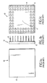
- PGA 10 includes a ceramic body 12 which supports a group of male contact pins 14.
- the pins may be arranged in a variety of footprints.
- a common footprint shown in Fig. 1c includes a desert region 17 containing no pins.
- a PGA 10 is often mounted to a printed circuit board i6 by inserting each pin 14 of the PGA into a corresponding socket 18, which is soldered into a plated through hole of the printed circuit board.
- the sockets are often supported in a molded plastic body 20 that is left in place.
- PGA 10 can be extracted by providing openings 22,24 in the printed circuit board 16 and carrier 20, respectively. Openings 22,24 are positioned beneath the inserted PGA 10, in the vicinity of a desert region (i.e., a region in which there are no pins extending from the PGA), and a knockout post of an extraction tool is passed through the openings to push PGA 10 out of sockets 18.
- a desert region i.e., a region in which there are no pins extending from the PGA
- FIG. 2c depicts an extraction jack screw 26 having a threaded knockout post 28.
- the inner walls of at least one of openings 22,24 are provided with a female thread 30 for mating with threaded knockout post 28.
- the threads are provided by a pem nut 32 pressed into either carrier 20 or printed circuit board 16. In the event that no carrier is present, as when a removable carrier is employed in installing the sockets, the pem nut is pressed into the circuit boards
- threaded knockout post 28 is screwed into mating thread 30 until knockout post 28 contacts desert region 17 of PGA 10. Further turning of the threaded knockout post 28 operates to push PGA 10 out of sockets 18.
- threaded knockout post 28 is attached to a gripping knob 34 having a diameter which is large relative to the diameter of driving post 28.
- threaded walls may be provided by removable pinch nut 36.
- Pinch nut 36 has a pair of tongues 38,40 which press together to allow insertion of the tongues through opening 22.
- the tongues are long enough to further extend through opening 24.
- Each tongue contains a lip 42,44 and a roughened surface 43,45.
- Aa post 2B engages the bottom surface of PGA 10, lips 44,46 are driven down, against the top surface of carrier 20, thereby providing the effective floor on which threaded post 28 stands as it pushes PGA 10 out of the sockets.
- a rigid knockout plate 50 may be secured to carrier 20 in a manner which allows the plate to move with threaded post 28 to drive PGA out of its socket.
- the knockout plate is chosen to have a larger surface than post 28 to thereby lessen the strain on the ceramic body of PGA 10.
- a variety of means may be employed to secure plate 50 to carrier 20, e.g., a pair of guide rods 52 disposed in apertures 56 in carrier 20.
- Guide rods 52 may be terminated with stops 58 for holding the rods and plate to the carrier as a single subassembly.
- Fig. 5b depicts an alternative knockout plate 60 for distributing the force of extraction beyond the desert region into regions having pins.
- knockout posts 62 of knockout plate 60 pass through apertures 64 in the printed circuit board and apertures 66 in carrier 20 to engage upon the bottom surface of PGA 10 in a variety of regions between the PGA pins.
- Knockout plate 60 is attached to a threaded knockout post 28 such that posts 62 operate to lift the PGA out of its socket as the threaded post is screwed into pem nut 32.
- Posts 62 are sufficiently long that the end 68 of threaded post 28 will not touch the ceramic body of PGA 10 during extraction.
- PGAs having desert regions large enough to accommodate a knockout post or plate.
- Many PGAs however are densely populated with a forest of pins, providing no desert region for use as a knockout surface.
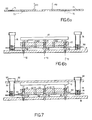
- Figs. 6a and 6b depict a knockout plate 160 for removing such PGAs.
- Knockout plate 160 includes apertures 70 for mating with sockets 18 to allow the knockout plate 160 to move along axis 72 of sockets 18.
- the knockout plate extends beyond PGA 10 and socket carrier 20 to allow threaded jack screws 76 to access threaded holes 74. As jack screws 76 bear down on the top surface of printed circuit board 16, they operate to lift knockout plate 160.
- Knockout posts 162 engage the bottom of PGA 10, lifting it from the sockets.
- Figs. 6a and 6b may also be employed as a means for inserting PGA 10.
- hold down blocks 80 are placed botween carrier 20 and knockout plate 160.
- Pull down cover 82 is placed across the top surface of PGA 10, beneath the heads 84 of threaded jack screws 76.
- knockout plate 160 risen until hold down blocks 80 are pressed against the underside of carrier 20. Since knockout plate 160 can rise no further, continued rotation of jack screws 76 operate to force pull down cover 82 against the top surface of PGA 10, thereby pressing pins 14 of PGA 10 into sockets 18.
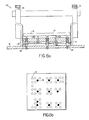
- knockout plate 160 may also be employed with a conventional extraction tool 88.
- Conventional extraction tool 88 includes a support leg 90 for standing on the top surface of printed circuit board 16.
- An extraction screw 92 is connected 10 lifting hook 94 to lift the hook as the extraction screw 92 is turned.
- the lifting hook grips the underside of PGA 10, thereby lifting it from sockets 18. however, this puts an unnecessarily large strain on ceramic body 12 of PGA 10.
- lifting hook 94 grips the underside of knockout plate 160, thereby lifting plate 160 to extract PGA 10.
- knockout posts 162 engage the bottom surface of the ceramic body 12 of PGA 10 at a variety of points 78 in the interstices of the forest of pins 14. Knockout plate 160 accordingly distributes the extraction force over the body 12 of PGA, thereby eliminating unnecessary strain.
Landscapes
- Connecting Device With Holders (AREA)
- Coupling Device And Connection With Printed Circuit (AREA)
- Manufacturing Of Electrical Connectors (AREA)
- Mounting Of Printed Circuit Boards And The Like (AREA)
Applications Claiming Priority (2)
| Application Number | Priority Date | Filing Date | Title |
|---|---|---|---|
| US07/434,006 US4985989A (en) | 1989-11-09 | 1989-11-09 | Method and apparatus for removing a multi-pin component installed in sockets on a circuit board |
| US434006 | 1989-11-09 |
Publications (2)
| Publication Number | Publication Date |
|---|---|
| EP0427560A2 true EP0427560A2 (de) | 1991-05-15 |
| EP0427560A3 EP0427560A3 (en) | 1991-10-16 |
Family
ID=23722429
Family Applications (1)
| Application Number | Title | Priority Date | Filing Date |
|---|---|---|---|
| EP19900312280 Withdrawn EP0427560A3 (en) | 1989-11-09 | 1990-11-09 | Removing a multi-pin component installed in sockets on a circuit board |
Country Status (5)
| Country | Link |
|---|---|
| US (1) | US4985989A (de) |
| EP (1) | EP0427560A3 (de) |
| JP (1) | JPH03241685A (de) |
| CN (1) | CN1052586A (de) |
| CA (1) | CA2029473A1 (de) |
Cited By (1)
| Publication number | Priority date | Publication date | Assignee | Title |
|---|---|---|---|---|
| EP0928050A3 (de) * | 1997-12-30 | 2000-03-15 | Honeywell Inc. | Elektrischer Steckverbinder für Leiterplattenaufbauten |
Families Citing this family (15)
| Publication number | Priority date | Publication date | Assignee | Title |
|---|---|---|---|---|
| US5287617A (en) * | 1992-08-11 | 1994-02-22 | Advanced Interconnections Corporation | Apparatus for extracting an integrated circuit package installed in a socket on a circuit board |
| US5562462A (en) * | 1994-07-19 | 1996-10-08 | Matsuba; Stanley | Reduced crosstalk and shielded adapter for mounting an integrated chip package on a circuit board like member |
| US5850691A (en) * | 1995-07-20 | 1998-12-22 | Dell Usa, L. P. | Method for securing an electronic component to a pin grid array socket |
| US5837556A (en) * | 1997-01-06 | 1998-11-17 | Sundstrand Corporation | Method of removing a component from a substrate |
| US20040111876A1 (en) * | 2002-12-13 | 2004-06-17 | Andrew Cheng | Reworking device for removing electrical elements mounted on motherboard |
| CN101783461B (zh) * | 2009-01-15 | 2012-02-29 | 精英电脑股份有限公司 | 连接器释放装置 |
| CN102500603B (zh) * | 2011-10-25 | 2015-01-07 | 陈道宝 | 分离磁带盒螺钉模具 |
| CN103203714B (zh) * | 2013-02-26 | 2015-02-04 | 青岛海信宽带多媒体技术有限公司 | 自动拔针机 |
| CN104564988A (zh) * | 2013-10-21 | 2015-04-29 | 艾默生(北京)仪表有限公司 | 螺栓配件及其安装和拆卸方法、和使用螺栓或螺母的装置 |
| US20150361739A1 (en) * | 2014-06-16 | 2015-12-17 | Chris Mechanical Services Ltd. | Gripper assembly for a coiled tubing injector |
| US9690128B2 (en) * | 2014-07-25 | 2017-06-27 | Lg Display Co., Ltd. | Liquid crystal display apparatus |
| CN108124382A (zh) * | 2016-11-29 | 2018-06-05 | 上海慧流云计算科技有限公司 | 电路板 |
| CN108321588A (zh) * | 2017-12-13 | 2018-07-24 | 天津津航计算技术研究所 | 一种可自由组合快速连接汇流装置 |
| CN112004366B (zh) * | 2020-07-30 | 2022-04-15 | 北京算能科技有限公司 | 电路板组件以及电子设备 |
| CN114063749A (zh) * | 2021-11-26 | 2022-02-18 | 张家港乐飞模型科技有限公司 | 一种便于拆装的航模用的信号转换模块 |
Family Cites Families (8)
| Publication number | Priority date | Publication date | Assignee | Title |
|---|---|---|---|---|
| US3588983A (en) * | 1969-03-10 | 1971-06-29 | Augat Inc | Extractor tool |
| FR2165023A7 (de) * | 1971-12-13 | 1973-08-03 | Crouzet Sa | |
| US4173813A (en) * | 1978-02-24 | 1979-11-13 | John M. Clayton, Jr. | Bearing puller |
| FR2552590B1 (fr) * | 1983-09-23 | 1986-03-28 | Nalbanti Georges | Support de boitier de circuit integre |
| US4597173A (en) * | 1984-06-20 | 1986-07-01 | The United States Of America As Represented By The Secretary Of The Navy | Electronic module insertion and retraction mechanism |
| DE3432102C2 (de) * | 1984-08-31 | 1987-04-23 | Siemens AG, 1000 Berlin und 8000 München | Vorrichtung zum Stecken und Ziehen von Flachbaugruppen |
| JPS632275A (ja) * | 1986-06-23 | 1988-01-07 | 山一電機工業株式会社 | Icソケツトにおけるic取出し機構 |
| US4800647A (en) * | 1987-09-14 | 1989-01-31 | General Electric Company | Electric module insertion tool |
-
1989
- 1989-11-09 US US07/434,006 patent/US4985989A/en not_active Expired - Fee Related
-
1990
- 1990-11-07 CA CA002029473A patent/CA2029473A1/en not_active Abandoned
- 1990-11-08 CN CN90109869A patent/CN1052586A/zh active Pending
- 1990-11-09 JP JP2305936A patent/JPH03241685A/ja active Pending
- 1990-11-09 EP EP19900312280 patent/EP0427560A3/en not_active Withdrawn
Cited By (1)
| Publication number | Priority date | Publication date | Assignee | Title |
|---|---|---|---|---|
| EP0928050A3 (de) * | 1997-12-30 | 2000-03-15 | Honeywell Inc. | Elektrischer Steckverbinder für Leiterplattenaufbauten |
Also Published As
| Publication number | Publication date |
|---|---|
| US4985989A (en) | 1991-01-22 |
| CA2029473A1 (en) | 1991-05-10 |
| JPH03241685A (ja) | 1991-10-28 |
| EP0427560A3 (en) | 1991-10-16 |
| CN1052586A (zh) | 1991-06-26 |
Similar Documents
| Publication | Publication Date | Title |
|---|---|---|
| US4985989A (en) | Method and apparatus for removing a multi-pin component installed in sockets on a circuit board | |
| US5038467A (en) | Apparatus and method for installation of multi-pin components on circuit boards | |
| US5076794A (en) | Space-saving mounting interconnection between electrical components and a printed circuit board | |
| US5145381A (en) | Wedge driven elastomeric connector | |
| US6229709B1 (en) | Printed circuit board card guide | |
| EP0676836B1 (de) | Elektrischer Verbinder mit Saugplattform zur Erleichterung des Aufnehmens | |
| US20040097119A1 (en) | Land grid array socket with reinforcing plate | |
| US7243417B2 (en) | Device for circuit board insertion and extraction | |
| CA2363826C (en) | Electronic device housing | |
| WO2000045467A1 (en) | Direct circuit to circuit stored energy connector | |
| GB2273830A (en) | Electrical contact elements for interposer structures | |
| US4979287A (en) | Tool for semiconductor chip removal | |
| US5597318A (en) | ZIF for plastic chip carrier | |
| US5873739A (en) | Direct circuit to circuit stored energy connector | |
| US6030243A (en) | Plug connector for card-edge mounting | |
| US5588861A (en) | ZIF chip socket | |
| US5348489A (en) | Socket assembly for an integrated circuit chip | |
| US4907976A (en) | Connector | |
| US6767220B2 (en) | Systems and methods for interconnecting electronic components | |
| US20040175967A1 (en) | Tool for attaching integrated circuit package to electrical connector | |
| US5733132A (en) | Socket for connecting an integrataed circuit to a printed wiring board | |
| US6796026B2 (en) | Tool for reworking a press-fit connector | |
| JP2758078B2 (ja) | コネクタ装置の設置方法およびコネクタ装置と回路板の結合体ならびにコネクタ装置と回路板を結合させる装置 | |
| JPH04103676U (ja) | 多層プリント基板の接続構造 | |
| CA1238479A (en) | Extractor for spring-lock pin connectors |
Legal Events
| Date | Code | Title | Description |
|---|---|---|---|
| PUAI | Public reference made under article 153(3) epc to a published international application that has entered the european phase |
Free format text: ORIGINAL CODE: 0009012 |
|
| AK | Designated contracting states |
Kind code of ref document: A2 Designated state(s): AT BE CH DE DK ES FR GB GR IT LI LU NL SE |
|
| PUAL | Search report despatched |
Free format text: ORIGINAL CODE: 0009013 |
|
| AK | Designated contracting states |
Kind code of ref document: A3 Designated state(s): AT BE CH DE DK ES FR GB GR IT LI LU NL SE |
|
| 17P | Request for examination filed |
Effective date: 19920325 |
|
| STAA | Information on the status of an ep patent application or granted ep patent |
Free format text: STATUS: THE APPLICATION HAS BEEN WITHDRAWN |
|
| 18W | Application withdrawn |
Withdrawal date: 19920928 |