EP0427635A1 - Leistungssteuerungseinrichtung, insbesondere Dimmer, mit Schutz gegen Kurzschluss und Überlastung - Google Patents
Leistungssteuerungseinrichtung, insbesondere Dimmer, mit Schutz gegen Kurzschluss und Überlastung Download PDFInfo
- Publication number
- EP0427635A1 EP0427635A1 EP90403179A EP90403179A EP0427635A1 EP 0427635 A1 EP0427635 A1 EP 0427635A1 EP 90403179 A EP90403179 A EP 90403179A EP 90403179 A EP90403179 A EP 90403179A EP 0427635 A1 EP0427635 A1 EP 0427635A1
- Authority
- EP
- European Patent Office
- Prior art keywords
- control device
- power control
- thermistor
- inductor
- protection against
- Prior art date
- Legal status (The legal status is an assumption and is not a legal conclusion. Google has not performed a legal analysis and makes no representation as to the accuracy of the status listed.)
- Granted
Links
- 230000004224 protection Effects 0.000 title claims abstract description 16
- 230000008878 coupling Effects 0.000 claims description 6
- 238000010168 coupling process Methods 0.000 claims description 6
- 238000005859 coupling reaction Methods 0.000 claims description 6
- 239000000463 material Substances 0.000 claims description 3
- 239000003990 capacitor Substances 0.000 description 7
- 238000010586 diagram Methods 0.000 description 2
- 239000000470 constituent Substances 0.000 description 1
- 230000006378 damage Effects 0.000 description 1
- 230000002950 deficient Effects 0.000 description 1
- 230000003111 delayed effect Effects 0.000 description 1
- 230000000694 effects Effects 0.000 description 1
- 238000010438 heat treatment Methods 0.000 description 1
- 238000002955 isolation Methods 0.000 description 1
- 238000000034 method Methods 0.000 description 1
- 229920000260 silastic Polymers 0.000 description 1
- 229920002379 silicone rubber Polymers 0.000 description 1
Images
Classifications
-
- H—ELECTRICITY
- H02—GENERATION; CONVERSION OR DISTRIBUTION OF ELECTRIC POWER
- H02H—EMERGENCY PROTECTIVE CIRCUIT ARRANGEMENTS
- H02H9/00—Emergency protective circuit arrangements for limiting excess current or voltage without disconnection
- H02H9/005—Emergency protective circuit arrangements for limiting excess current or voltage without disconnection avoiding undesired transient conditions
-
- H—ELECTRICITY
- H02—GENERATION; CONVERSION OR DISTRIBUTION OF ELECTRIC POWER
- H02H—EMERGENCY PROTECTIVE CIRCUIT ARRANGEMENTS
- H02H9/00—Emergency protective circuit arrangements for limiting excess current or voltage without disconnection
- H02H9/02—Emergency protective circuit arrangements for limiting excess current or voltage without disconnection responsive to excess current
- H02H9/026—Current limitation using PTC resistors, i.e. resistors with a large positive temperature coefficient
Definitions
- the present invention relates generally to power control devices of the kind using a triac, and it relates more particularly, but not necessarily exclusively, to the case where they are dimmers.
- the triac for the control of the triac implemented, it intervenes, on the triac trigger circuit, a certain number of components, and, in particular, a capacitor charged by a network of resistors including a potentiometer whose order is available to the user.
- a suppressor circuit comprising at least one inductance and at least one capacitor.
- the present invention generally relates to a provision making it possible to satisfy this latter requirement in a very simple manner, using only the components already available, and therefore free of charge. additional.
- a power control device in particular a light dimmer, of the type comprising, on the one hand, a triac on the trigger circuit which intervenes, in particular, for protection against short- circuits, a thermistor with positive temperature coefficient, and, on the other hand, a suppressor circuit comprising, in particular, an inductance, this control device being generally characterized in that, to also provide protection against overloads, the thermistor is thermally coupled with the inductor.
- the inductance being a torus
- the thermistor is placed in the center of this torus, being there if desired embedded in a thermal coupling mass, the constituent material of which is an electrically insulating product and having good thermal conductivity.
- the thermistor sees its resistance increased when the temperature of the inductor increases, which is the case during overloads, and, the load resistance of the capacitor controlling the triac trigger increasing due to that of this thermistor, the conduction control of this triac is thereby delayed by each alternation.
- the power control device according to the invention can advantageously return to an equilibrium temperature before destruction of its most exposed components.
- an additional advantage is taken of the thermistor used, this thermistor not only providing protection against short circuits, but also protection against overloads.
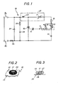
- Figure 1 we recognize the diagram of a power control device of the kind operating between the terminals B1 by which it is adapted to be connected to any AC power source, in practice the usual network of electrical distribution, and the terminals B2 by which it is able to be connected to the load to be served, for example a lighting circuit, a triac 10.
- this triac 10 intervenes, via a diac 11, a capacitor 12 charged by a network of resistors including, on the one hand, a potentiometer 13, the control of which , which is available to the user, also controls an on-off switch 14, and which is in series with a resistor 15 while also having a resistor 16 bypass at its terminals, and, on the other hand, by series with this potentiometer 13 and the resistor 15, for protection against short-circuits, a thermistor with a positive temperature coefficient 17.
- the power control device further comprises, between the terminals B1, B2 and the triac 10, a suppressor circuit 19 comprising an inductance 20 and a capacitor 21.
- an "anti-flicker” circuit comprising a capacitor 22 and a resistor 23.
- a fuse 24 is provided for the general protection of the assembly.
- the thermistor 17 is thermally coupled to the inductor 20.
- the thermistor 17 is preferably placed in the center of this torus.
- the assembly is carried by a printed circuit board 26, with the other components, not shown, concerned.
- the internal volume of the toroid thus forming the inductor 20 then advantageously contains a thermal coupling mass 27 in which the thermistor 17 is embedded.
- this thermal coupling mass 27 is an insulating product from the electrical point of view and having good thermal conductivity.
- silicone elastomer called "SILASTIC JRTV", two-component brand DOW CORNING, gives satisfaction on this subject.
- the thermistor 17 can also be advantageously surrounded by a heat-shrinkable sheath which ensures its electrical isolation even if its centering in the toroid forming the inductor 20 is defective.
- this thermistor 17 advantageously ensures, by she- even, according to the process described above, protection against such an overload.
Landscapes
- Engineering & Computer Science (AREA)
- Power Engineering (AREA)
- Circuit Arrangement For Electric Light Sources In General (AREA)
- Thermistors And Varistors (AREA)
Applications Claiming Priority (2)
| Application Number | Priority Date | Filing Date | Title |
|---|---|---|---|
| FR8914697 | 1989-11-09 | ||
| FR8914697A FR2654269B1 (fr) | 1989-11-09 | 1989-11-09 | Dispositif de commande de puissance, notamment variateur de lumiere, protection contre les courts-circuits et les surcharges. |
Publications (2)
| Publication Number | Publication Date |
|---|---|
| EP0427635A1 true EP0427635A1 (de) | 1991-05-15 |
| EP0427635B1 EP0427635B1 (de) | 1994-04-20 |
Family
ID=9387230
Family Applications (1)
| Application Number | Title | Priority Date | Filing Date |
|---|---|---|---|
| EP19900403179 Expired - Lifetime EP0427635B1 (de) | 1989-11-09 | 1990-11-08 | Leistungssteuerungseinrichtung, insbesondere Dimmer, mit Schutz gegen Kurzschluss und Überlastung |
Country Status (3)
| Country | Link |
|---|---|
| EP (1) | EP0427635B1 (de) |
| DE (1) | DE69008311T2 (de) |
| FR (1) | FR2654269B1 (de) |
Cited By (4)
| Publication number | Priority date | Publication date | Assignee | Title |
|---|---|---|---|---|
| EP0800334A3 (de) * | 1996-04-02 | 1999-03-10 | Patent-Treuhand-Gesellschaft für elektrische Glühlampen mbH | Schaltungsanordnung zum Betreiben von elektrischen Lampen |
| GB2399958A (en) * | 2003-03-26 | 2004-09-29 | Jin Wu | Decorative lighting circuit with overcurrent protection |
| CN102394495A (zh) * | 2011-10-09 | 2012-03-28 | 杭州乾龙电器有限公司 | 动态热保护型过压保护器 |
| CN102882181A (zh) * | 2012-09-29 | 2013-01-16 | 深圳市新国都技术股份有限公司 | 一种基于双向可控硅的反接保护及过压保护电路 |
Citations (2)
| Publication number | Priority date | Publication date | Assignee | Title |
|---|---|---|---|---|
| US3708720A (en) * | 1973-01-02 | 1973-01-02 | Franklin Electric Co Inc | Semiconductor thermal protection |
| DE8703701U1 (de) * | 1987-03-12 | 1987-04-23 | Obo Bettermann Ohg, 58710 Menden | Überspannungsschutzvorrichtung |
-
1989
- 1989-11-09 FR FR8914697A patent/FR2654269B1/fr not_active Expired - Fee Related
-
1990
- 1990-11-08 DE DE1990608311 patent/DE69008311T2/de not_active Expired - Fee Related
- 1990-11-08 EP EP19900403179 patent/EP0427635B1/de not_active Expired - Lifetime
Patent Citations (2)
| Publication number | Priority date | Publication date | Assignee | Title |
|---|---|---|---|---|
| US3708720A (en) * | 1973-01-02 | 1973-01-02 | Franklin Electric Co Inc | Semiconductor thermal protection |
| DE8703701U1 (de) * | 1987-03-12 | 1987-04-23 | Obo Bettermann Ohg, 58710 Menden | Überspannungsschutzvorrichtung |
Non-Patent Citations (1)
| Title |
|---|
| ELECTRONIQUE APPLICATIONS. no. 47, avril 1986, PARIS FR pages 53 - 55; "Gradateurs de lumière: montages simples ne générant pas de parasites." * |
Cited By (5)
| Publication number | Priority date | Publication date | Assignee | Title |
|---|---|---|---|---|
| EP0800334A3 (de) * | 1996-04-02 | 1999-03-10 | Patent-Treuhand-Gesellschaft für elektrische Glühlampen mbH | Schaltungsanordnung zum Betreiben von elektrischen Lampen |
| GB2399958A (en) * | 2003-03-26 | 2004-09-29 | Jin Wu | Decorative lighting circuit with overcurrent protection |
| CN102394495A (zh) * | 2011-10-09 | 2012-03-28 | 杭州乾龙电器有限公司 | 动态热保护型过压保护器 |
| CN102882181A (zh) * | 2012-09-29 | 2013-01-16 | 深圳市新国都技术股份有限公司 | 一种基于双向可控硅的反接保护及过压保护电路 |
| CN102882181B (zh) * | 2012-09-29 | 2015-02-25 | 深圳市新国都技术股份有限公司 | 一种基于双向可控硅的反接保护及过压保护电路 |
Also Published As
| Publication number | Publication date |
|---|---|
| FR2654269B1 (fr) | 1992-02-07 |
| DE69008311T2 (de) | 1994-08-04 |
| EP0427635B1 (de) | 1994-04-20 |
| FR2654269A1 (fr) | 1991-05-10 |
| DE69008311D1 (de) | 1994-05-26 |
Similar Documents
| Publication | Publication Date | Title |
|---|---|---|
| FR2772524A1 (fr) | Dispositif de protection contre des surintensites, notamment pour la protection rearmable d'un interrupteur controle | |
| FR2570873A1 (fr) | Circuit indicateur pour disjoncteur | |
| EP0427635B1 (de) | Leistungssteuerungseinrichtung, insbesondere Dimmer, mit Schutz gegen Kurzschluss und Überlastung | |
| EP0284592B1 (de) | Einrichtung zum Ermöglichen der Wiederherstellung des Stroms einer Leitung im Falle des Durchschlagens eines oder mehrerer Elemente einer Serienschaltung | |
| FR2491592A1 (fr) | Bougie a incandescence | |
| FR2493625A1 (fr) | Circuit protecteur pour accessoire chauffant electrique, notamment couverture chauffante | |
| FR2485285A1 (fr) | Couverture electrique chauffante a circuit de securite | |
| FR2528655A1 (fr) | Ballast pour lampe a incandescence basse tension et lampe ainsi obtenue | |
| JPH03207915A (ja) | 過負荷保護装置を備えた電気式シガレットライター | |
| FR2687514A1 (fr) | Dispositif-variateur de l'intensite du courant electrique dans un recepteur. | |
| US4438344A (en) | Switched rectifier disc for Edison sockets | |
| CA1184224A (fr) | Coupe-circuit a commande programmable | |
| FR2793104A1 (fr) | Procede de pilotage d'un element chauffant d'appareil electrique de chauffage de liquide | |
| FR2767614A1 (fr) | Interrupteur electronique | |
| FR2735279A3 (fr) | Montage a resistances pour un commutateur electromagnetique destine a commuter des charges capacitives | |
| FR2499808A1 (fr) | Table de cuisson electrique munie d'un dispositif avertisseur de temperature | |
| FR2771587A1 (fr) | Relais-shunt pour lampe electrique basse tension, montee en serie | |
| FR2630583A1 (fr) | Dispositif de decrochage de tension minimale | |
| FR2675004A3 (fr) | Starter pour des lampes a decharge a basse pression alimentees par un courant alternatif. | |
| FR2827077A1 (fr) | Fusible a coupure integrale comportant un element polymere limiteur de courant chauffant une liaison thermofusible | |
| FR2936645A1 (fr) | Cable electrique d'alimentation presentant un fusible de protection contre son echauffement. | |
| CA2336792A1 (en) | Cigar lighter with ptc thermal protection | |
| FR2600464A3 (fr) | Dispositif de commande d'elements de resistance electrique armes | |
| WO1999010904A1 (fr) | Four a micro-ondes comportant un dispositif de limitation du courant d'appel | |
| FR2616579A1 (fr) | Interrupteur par commande a bouton-poussoir a impulsion |
Legal Events
| Date | Code | Title | Description |
|---|---|---|---|
| PUAI | Public reference made under article 153(3) epc to a published international application that has entered the european phase |
Free format text: ORIGINAL CODE: 0009012 |
|
| AK | Designated contracting states |
Kind code of ref document: A1 Designated state(s): DE GB IT |
|
| 17P | Request for examination filed |
Effective date: 19910610 |
|
| 17Q | First examination report despatched |
Effective date: 19921228 |
|
| GRAA | (expected) grant |
Free format text: ORIGINAL CODE: 0009210 |
|
| AK | Designated contracting states |
Kind code of ref document: B1 Designated state(s): DE GB IT |
|
| GBT | Gb: translation of ep patent filed (gb section 77(6)(a)/1977) |
Effective date: 19940420 |
|
| REF | Corresponds to: |
Ref document number: 69008311 Country of ref document: DE Date of ref document: 19940526 |
|
| 111L | Licence recorded |
Free format text: 0100 LEGRAND SNC |
|
| ITF | It: translation for a ep patent filed | ||
| PLBE | No opposition filed within time limit |
Free format text: ORIGINAL CODE: 0009261 |
|
| STAA | Information on the status of an ep patent application or granted ep patent |
Free format text: STATUS: NO OPPOSITION FILED WITHIN TIME LIMIT |
|
| 26N | No opposition filed | ||
| REG | Reference to a national code |
Ref country code: GB Ref legal event code: IF02 |
|
| PGFP | Annual fee paid to national office [announced via postgrant information from national office to epo] |
Ref country code: GB Payment date: 20051028 Year of fee payment: 16 |
|
| PGFP | Annual fee paid to national office [announced via postgrant information from national office to epo] |
Ref country code: DE Payment date: 20051107 Year of fee payment: 16 |
|
| PGFP | Annual fee paid to national office [announced via postgrant information from national office to epo] |
Ref country code: IT Payment date: 20061130 Year of fee payment: 17 |
|
| PG25 | Lapsed in a contracting state [announced via postgrant information from national office to epo] |
Ref country code: DE Free format text: LAPSE BECAUSE OF NON-PAYMENT OF DUE FEES Effective date: 20070601 |
|
| GBPC | Gb: european patent ceased through non-payment of renewal fee |
Effective date: 20061108 |
|
| PG25 | Lapsed in a contracting state [announced via postgrant information from national office to epo] |
Ref country code: GB Free format text: LAPSE BECAUSE OF NON-PAYMENT OF DUE FEES Effective date: 20061108 |
|
| PG25 | Lapsed in a contracting state [announced via postgrant information from national office to epo] |
Ref country code: IT Free format text: LAPSE BECAUSE OF NON-PAYMENT OF DUE FEES Effective date: 20071108 |