EP0427642B1 - Einrichtung zur Kühlung eines Induktors in einem Linearmotor - Google Patents
Einrichtung zur Kühlung eines Induktors in einem Linearmotor Download PDFInfo
- Publication number
- EP0427642B1 EP0427642B1 EP90420460A EP90420460A EP0427642B1 EP 0427642 B1 EP0427642 B1 EP 0427642B1 EP 90420460 A EP90420460 A EP 90420460A EP 90420460 A EP90420460 A EP 90420460A EP 0427642 B1 EP0427642 B1 EP 0427642B1
- Authority
- EP
- European Patent Office
- Prior art keywords
- openings
- support screen
- coil
- separator
- positioning
- Prior art date
- Legal status (The legal status is an assumption and is not a legal conclusion. Google has not performed a legal analysis and makes no representation as to the accuracy of the status listed.)
- Expired - Lifetime
Links
- 238000001816 cooling Methods 0.000 title claims description 18
- 229920002994 synthetic fiber Polymers 0.000 claims description 13
- 239000004020 conductor Substances 0.000 claims description 11
- 239000012809 cooling fluid Substances 0.000 claims description 10
- 238000005192 partition Methods 0.000 claims description 10
- 239000012530 fluid Substances 0.000 claims description 5
- 230000005465 channeling Effects 0.000 claims description 4
- 238000004891 communication Methods 0.000 claims description 4
- 230000015572 biosynthetic process Effects 0.000 claims description 2
- 230000000295 complement effect Effects 0.000 claims description 2
- 125000006850 spacer group Chemical group 0.000 description 40
- 235000012431 wafers Nutrition 0.000 description 26
- 238000009413 insulation Methods 0.000 description 4
- 239000011810 insulating material Substances 0.000 description 3
- 239000004033 plastic Substances 0.000 description 3
- 238000010276 construction Methods 0.000 description 2
- 238000010292 electrical insulation Methods 0.000 description 2
- 238000004519 manufacturing process Methods 0.000 description 2
- 239000000463 material Substances 0.000 description 2
- 210000001520 comb Anatomy 0.000 description 1
- 150000001875 compounds Chemical class 0.000 description 1
- 239000002826 coolant Substances 0.000 description 1
- 230000000694 effects Effects 0.000 description 1
- 230000005611 electricity Effects 0.000 description 1
- 239000003365 glass fiber Substances 0.000 description 1
- 238000011065 in-situ storage Methods 0.000 description 1
- 238000001746 injection moulding Methods 0.000 description 1
- 239000012212 insulator Substances 0.000 description 1
- 239000002184 metal Substances 0.000 description 1
- 239000012764 mineral filler Substances 0.000 description 1
- 230000002093 peripheral effect Effects 0.000 description 1
- 125000000843 phenylene group Chemical group C1(=C(C=CC=C1)*)* 0.000 description 1
- 229920001021 polysulfide Polymers 0.000 description 1
- 239000005077 polysulfide Substances 0.000 description 1
- 150000008117 polysulfides Polymers 0.000 description 1
- 230000003014 reinforcing effect Effects 0.000 description 1
- 238000007493 shaping process Methods 0.000 description 1
- 229920003002 synthetic resin Polymers 0.000 description 1
- 239000000057 synthetic resin Substances 0.000 description 1
- 238000011144 upstream manufacturing Methods 0.000 description 1
Images


Classifications
-
- H—ELECTRICITY
- H02—GENERATION; CONVERSION OR DISTRIBUTION OF ELECTRIC POWER
- H02K—DYNAMO-ELECTRIC MACHINES
- H02K9/00—Arrangements for cooling or ventilating
-
- H—ELECTRICITY
- H02—GENERATION; CONVERSION OR DISTRIBUTION OF ELECTRIC POWER
- H02K—DYNAMO-ELECTRIC MACHINES
- H02K3/00—Details of windings
- H02K3/04—Windings characterised by the conductor shape, form or construction, e.g. with bar conductors
- H02K3/24—Windings characterised by the conductor shape, form or construction, e.g. with bar conductors with channels or ducts for cooling medium between the conductors
-
- H—ELECTRICITY
- H02—GENERATION; CONVERSION OR DISTRIBUTION OF ELECTRIC POWER
- H02K—DYNAMO-ELECTRIC MACHINES
- H02K41/00—Propulsion systems in which a rigid body is moved along a path due to dynamo-electric interaction between the body and a magnetic field travelling along the path
- H02K41/02—Linear motors; Sectional motors
- H02K41/025—Asynchronous motors
Definitions
- the invention relates to linear motors whose inductor comprises a prismatic axial core surrounded by coils which, formed of wafers separated by magnetic isthmus, are juxtaposed by one of their faces to the core of a support in U, made of a material that is good conductor of electricity, constituting a screen against magnetic leaks, while the armature has a U-shaped cross section covering the inductor.
- each coil wafer framed by two magnetic isthmus, is spaced from its neighbor by a spacer comprising an annular cooling channel.
- This channel communicates with slots in the screen support, slots themselves opening into chambers, respectively central and lateral, delimited in this support by partition walls. At least one of these chambers is connected to means forcibly sending it a cooling fluid.
- the screen support is associated with cooling profiles on which the cooling fluid passes.
- the cooling fluid which generally consists of air, enters one of the chambers of the screen support, circulates in the spacers to cool the wafers of the coils, then returns to the other chambers of the support. screen before being evacuated, with the additional cooling flow of the support profiles.
- this circuit implements means for separating the chambers, distributing and channeling the flows which are not very compatible with mass production and have a significant effect on the final cost of the engine, both by their design and by their mounting condition.
- the object of the present invention is to provide a device for cooling which, while being less expensive and easy to assemble, both for unitary construction and for series construction, provides better cooling and improves efficiency.
- each of the disc spacers is made of molded synthetic material, on the other hand, has an inner wall and an outer wall forming a closed C channel communicating, by openings in its outer wall and at the ends of the C, with the openings in the support screen, and moreover, has, between the two openings, a groove for positioning the base of a longitudinal bar of synthetic material, while that the core of the screen support is capped, on its side facing the axial core, by an insulating cover of synthetic material provided, on one side, with wells engaging in the openings of this core and, on the other side, two parallel, spaced longitudinal grooves for positioning the top of a pair of bars, and each of the bars constituting a partition in an intermediate chamber formed between the cover insulating ring and the coil, is provided at each of its ends with positioning means capable of cooperating with complementary means provided in plastic flanges delimiting each coil.
- the spacers, the insulating cover, the longitudinal bars and the flanges are made of molded synthetic material, have regular dimensions allowing them to be easily assembled by interlocking and to form partitions and walls channeling the cooling flow, while ensuring the desired electrical insulation without recourse to any other external means.
- the use of a synthetic material having good insulation characteristics makes it possible to improve the mechanical resistance to temperature, to reduce the thicknesses of the walls of the elements and, consequently, to reduce the dimensions of the inductor, while improving its magnetic characteristics.
- plastic spacers associated with plasticized sheets on their large faces eliminates any insulating sheets of interleaving between the elements of a coil, which facilitates mounting and above all improves the heat transfers between each wafer and the juxtaposed channels of the cooling circuit.
- the insulation of the screen support by an independent cover to replace an insulating layer formed in situ makes it possible to control the insulation obtained by the cover before it is mounted on the screen and if this insulation fails to replace the cover. easily without having to put off the screen.
- the wings of the U-shaped screen support are turned away from the axial core and form, with two partitions parallel to them and interposed between the core of the support and an insulating base opposite to this core, a central chamber for the arrival of the cooling fluid, a chamber communicating with openings in this base, and two lateral chambers for the outlet of this fluid, while the radiator elements associated with the screen support consist of fins fixed against the internal face of each wing of the screen support, in the corresponding lateral chamber, and that the mouths of each spacer are offset laterally relative to its median plane, in order to ensure communication with the central chamber and one of the lateral chambers , whatever the mounting direction given to the spacer.
- the screen support constitutes a first distribution chamber which, upstream of the coil, channels the arrival of cooling fluid and directs it, through its central chamber, towards the spacers, while each of its chambers side receives the fluid heated by circulation in the spacers, fluid which is still used to cool the screen support by passing over the cooling fins attached to its side walls.
- the particular arrangement of the mouths of the spacers makes it possible to use the same type of spacer, whatever its mounting direction, that is to say allows to alternate the spacers so that the outlet of each of them communicates with a side chamber which is different from that with which the outlet openings of the juxtaposed spacers communicate. Such an arrangement reduces the cost of manufacturing the spacers and simplifies the assembly since it suffices to return the spacers to the assembly to obtain the desired reversal of the directions of circulation.
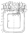
- this linear motor is constituted by an armature and by an inductor, designated respectively by A and B.
- the armature A has in cross section the general shape of a U and is composed a magnetic part 2 internally covered with a conductive part 3.
- the inductor B is composed of a prismatic axial core 4 surrounded by coils generally designated by 5, one of the faces, and n the occurrence the upper one is juxtaposed to the core 6a of a U-shaped section support, constituting a magnetic screen and designated for the rest of the description by the expression "screen support 6".
- the latter is made of heat conductive material.
- the core 4 of square section is advantageously composed of metal bars 4a of small section distributed in regular rows and columns and immobilized, after rectilinear or curvilinear shaping in the direction of their length, by a layer of synthetic material 4b molded onto them.
- Each coil 5 is, in known manner, composed of wafers of gimped electrically conductive wires 5a and 5b, linked in pairs by a connecting conductor, not shown, so as to form double wafers, of the type shown in Figure 6.
- Each of the wafers of a double wafer is secured to a terminal 7a or 7b to ensure its electrical connection.
- Each wafer is associated on each of its transverse faces with a laminated sheet 8 constituting a magnetic isthmus and which is itself separated from the sheet juxtaposed with the neighboring wafer by a spacer, generally designated by 9.
- the sheet 8 is covered , at least on its face turned to the outside of the spacer, by a layer of synthetic insulating material. As for the spacer, it delimits an annular cooling channel 10 connected to openings 12 and 13 formed in the core 6a of the screen support 6.
- Each coil is delimited longitudinally, and on each side, by a flange, intermediate 15 or end 15a.
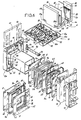
- Several coils, and for example three, are thus fixed by the intermediate flanges 15 and by the end flanges 15a to the same section of support screen 6, section whose core is capped by the same cover 16 made of insulating material.
- the assembly thus obtained forms a half pole of the linear motor.
- each coil of this assembly is connected in series with one of the coils of another half pole to constitute one of the phases of this motor.
- the screen support 6 has, in cross section, the shape of a U whose wings 6b are turned away from the axial core 4 and delimit between them a cavity which is closed in the upper part, by a base made of insulating material 17 (FIG. 1), and at the ends by the walls 63 of the flanges 15A.
- This cavity is internally divided by two longitudinal partitions 18, into three compartments, namely a central inlet compartment 19, and two lateral outlet compartments 20.
- the compartment 19 communicates through openings 22, visible in particular in Figures 2 and 4 , with a source of pressurized coolant and, for example, a forced air source.
- the lateral outlet compartments 20 communicate with the outside, either by openings made directly in the base 17, or by openings 23 formed in the wings 6b of the screen support 6 and communicating with exhaust pipes 24 (FIG. 1 ).
- FIG. 1 shows that each lateral compartment 20 also serves as a housing for cooling fins 25 projecting from combs fixed on the internal face of the wings 6b of the screen support 6. These fins are arranged in the outlet path of the cooling fluid s' escaping through the openings 13 of the core.
- FIG. 1 also shows that the central 12 and lateral 13 openings of the core 6 are capped by wells 12a and 13a projecting from the insulating cover 16, cover provided with a skirt 16a encircling the core as shown in FIG. 1.
- FIG. 6 shows that this skirt 16a locally includes knockouts 26 and 27 covering knockouts respectively 26a and 27a formed in the screen support 6.
- Each of the spacers 9a-9b forming with two magnetic isthmus 8 a hollow ventilated tooth is constituted by a piece of molded synthetic material and has, as shown in Figures 5 and 6, an inner wall 30 and an outer wall 32 defining between them a channel 10 having the shape of a closed C.
- This channel opens to the outside via vents, respectively, outside 33 and inside 34.
- the vents 34 and 33 are offset with respect to the median plane P1 of the retractor so that the same retractor can alternately be arranged with its mouths on one side or the other side of the plane P1.
- This figure also shows that the outlets open below the core 6a of the support screen 6 in a so-called intermediate chamber and generally designated by 35.
- each spacer 9a-9b The internal and external walls 30 and 32 of each spacer 9a-9b are provided, on their opposite faces delimiting the channel 10 and in the zones of change of direction thereof with protrusions 36 channeling the fluid and avoiding the formation of vortex currents in the angles.
- the two mouths 33 and 34 are separated by a groove 37 which is extended by a slot 38 crossing the inner wall 30. The latter is used for the passage of the connecting conductor between the two wafers of a double wafer, during the mounting of a spacer between these two wafers.
- the internal wall 30 is provided, on one of its sides, with an oblique transverse groove 39 serving as housing for the connecting conductor between the two wafers, when the 'spacer 9a-9b is in its final position between the two wafers.
- the protrusions 36 are provided locally with longitudinal pins 40 capable of cooperating with holes 42 formed, as shown in FIG. 6, in each of the sheets 8 constituting the magnetic isthmus, to ensure the positioning of these isthmus relative to the retractor.
- the spacer 9a described above is intended to be placed at the ends of the coil, in the flanges 15a or 15. It is associated with spacers 9b, of the same shape and structure as it but also comprising a peripheral rib 43 reinforcing its outer wall and giving it, as shown in Figures 6 and 3, a cross section in T.
- a rib improves the positioning of the sheets 8, but also allows to position the wafers relative to the spacer.
- This rib extends above the openings 33 and 34 to reinforce the yoke 44 used to position the spacer 9a-9b, relative to the insulating cover 16.
- each of the laminated sheets 8 forms, in side view, a square ring of which one of the sides is split at 45.
- This slot is used for the passage of the connecting conductor of two wafers during the 'introduction of the sheet 8 in the interval between the two wafers of a double wafer.
- Each of the flanges 15 or 15a comprises, (FIG. 6), projecting from its face facing the coil with which it cooperates, on the one hand, a mandrel 50 of square section able to be crossed by the magnetic core 4 and to receive by fitting the end of the sleeve 14, on the other hand and around this mandrel, two ribs respectively interior 52 and exterior 53, delimiting between them a C 54 channel similar to that delimited in the spacers and, finally, isthmus positioning stops 55 magnetic 8 corresponding.
- the channel 54 delimited between the diametrical wall of the corresponding flange and the laminated sheet 8, communicates through openings 56 and 57 with the intermediate chamber 35 previously described, that is to say with the gap formed between the top of the coil and the insulated core of the screen support 6.
- the diametrical wall of the flange is also integral with a skirt 58 capable of surrounding the coil on three sides and extending beyond the upper face of this coil to form a fixing yoke 59.
- the two wings of this yoke are connected by a crosspiece 60 locally comprising mortises 62, the usefulness of which will be specified below.
- each end flange 15a comprises, in addition to the elements described above, a transverse wall 63 extending beyond the yoke 59 and constituting means for closing the ends of the screen support 6, as this is shown in FIG. 2.
- This wall has grooves 64 for positioning the partitions 18.
- the spacers 9a-9b, the sleeve 14, the flanges 15 and 15a and the insulating cover 16 are produced by injection molding of the same synthetic material, chosen for its electrical insulation properties and its thermal stability, but also for its dimensional stability and for example in a compound based on phenylene polysulfide, glass fibers and mineral fillers. Thanks to their embodiment, the various components of the cooling device have stable dimensional characteristics favoring their mounting and their assembly with sockets.
- FIG. 3 also shows, in the assembled state, a coil made up of a succession of plastic parts inserted between wafers and sheets 8 forming magnetic isthmus, namely, going from left to right, a flange 15, a sheet 8, a wafer 5a, a spacer 9a, positioning two sheets 8, another wafer 5b, a spacer 9b positioning two sheets 8 and so on to the other flange 15a.
- Each spacer is positioned on the sleeve 14 and, by its yoke 44 on the insulating cover 16, and each flange is fixed by its yokes 59 on the knockout 26 or 27 of the insulating cover 16 to form a rigid structure.
- each of the bars 70 is assigned to one of the two series of spacers, namely to the series comprising all the vents arranged on the same side of the median plane of the inductor.
- This bar is positioned by its base in the grooves 37 formed between the mouths 33 and 34 of each spacer 9a-9b, but also by engagement of its top in a longitudinal groove 72 formed in the core of the insulating cover 16.
- each bar is provided with lateral protrusions 73 forming tenons capable of engaging in the mortises 62 formed in the flanges 15 and 15a.
- each bar is provided at one of its ends with a tubular barrel 74 projecting upward and perpendicular to its longitudinal direction. This gun is intended to be used for guiding and passing the conductor 75 connecting one of the terminals of the coil to a connection plug 76 passing through the base 17 as shown in FIG. 2.
- FIG. 3 shows that the insulating cover 16 is provided with transverse grooves 76 for positioning the crosspieces 60 of the flanges 15. This interlocking also constitutes an extreme closure means for the intermediate chamber 35 associated with the coil arranged between the two flanges.
- the two bars 70 form two longitudinal partitions dividing the intermediate chamber 35 into three compartments, namely a central compartment 35a, and two lateral compartments 35b.
- the central compartment 35a puts the central chamber 19 of the screen support 6 into communication with the inlet openings 34 of the spacers but also with the openings 56 of the channels 54 of the flanges.
- the lateral compartments 35b ensure the communication of the lateral mouths 33 of the spacers and the lateral openings 57 of the flanges with the lateral chambers 20 of the insulating support 6 and thus allow the air flow, coming to cool each of the hollow magnetic teeth, to penetrate into the insulating support for skirting the fins 25 before escaping through a manifold, either directly outside or through a heat exchanger.
- each of the barrels 74 is arranged so as to pass through one of the openings 12 of the core 6a of the screen support 6 without forming a significant protrusion which can disturb the circulation of the cooling fluid.
- the cooling device according to the invention differs from those described in the prior art, by the structure of the screen support of the inductor and by the structure of the means organizing the distribution network and collection of the cooling flow, the latter means being arranged to be easy to assemble, to reduce the thicknesses and dimensions, to improve the heat exchanges with equal air flow, and lead to an improvement in the power factor and in the efficiency of the engine .
Landscapes
- Engineering & Computer Science (AREA)
- Power Engineering (AREA)
- Physics & Mathematics (AREA)
- Chemical & Material Sciences (AREA)
- Combustion & Propulsion (AREA)
- Electromagnetism (AREA)
- Linear Motors (AREA)
- Electromagnets (AREA)
- Motor Or Generator Cooling System (AREA)
- General Induction Heating (AREA)
Claims (10)
- Kühlvorrichtung für einen Linearmotorinduktor, wobei der Induktor einen von mehreren Wicklungen (5) umgebenen, axialen, prismatischen Kern (4) umfaßt, welche Wicklungen, von denen jede aus durch Magnetisthmen getrennten Flachspulen (5a-5b) gebildet ist, mit einer ihrer Seiten neben den Kern (6a) eines eine magnetische Abschirmung bildenden U-Trägers gesetzt sind, bei welcher Vorrichtung einerseits jede Flachspule (5a-5b) von jeder ihrer Nachbarspulen durch einen Abstandhalter (9) getrennt ist, der mit den entsprechenden Isthmen (8) einen mit Spalten (12-13) des Abschirmträgers (6) in Verbindung stehenden ringförmigen Kühlkanal bildet, und andererseits der Abschirmträger (6) mit einer Kühlfluideingangs- und -ausgangsöffnungen aufweisenden isolierenden Umhüllung einen Hohlraum bildet, der durch Trennwände (18) in eine Zentralkammer (19) und zwei Seitenkammern (20) unterteilt ist, und die Flügelwände (6b) des Abschirmträgers (6) mit Elementen verbunden sind, welche Kühler bilden, an denen das Kühlfluid entlangfließt,
dadurch gekennzeichnet, daß
jeder der Abstandhalter (9a-9b) der Flachspulen aus geformtem Kunststoffmaterial hergestellt ist, eine Innenwand (30) und eine Außenwand (32) aufweist, welche einen Kanal in Gestalt eines geschlossenen C bilden, der über in seiner Außenwand und an den Enden des C angeordnete Mündungen (33-34) mit den in dem Abschirmträger (6) ausgebildeten Öffnungen (13-12) in Verbindung steht, und zwischen den zwei Mündungen (33-34) einen Einschnitt (37) zum Positionieren der Basis eines longitudinalen Stegs (70) aus Kunststoffmaterial aufweist, während der Kern (6a) des Abschirmträgers (6) auf seiner zum axialen Kern (4) hin gerichteten Seite durch eine isolierende Abdeckung (16) aus Kunststoffmaterial überdeckt ist, welche einerseits mit in die Öffnungen (12-13) dieses Kerns eingreifenden Schächten (12a-13a) ausgestattet ist, sowie andererseits mit zwei parallelen und beabstandeten longitudinalen Einschnitten (72) zur Positionierung der Spitze eines Paars von Stegen (70), und daß jeder der in einer zwischen der isolierenden Abdeckung (16) und der Wicklung (5) angeordneten Zwischenkammer (35) eine Trennwand bildenden Stege (70) an jedem seiner Enden Positioniermittel (73) aufweist, welche geeignet sind, mit komplementären Mitteln (62) zusammenzuwirken, welche in jede Wicklung (5) longitudinal begrenzenden Wangen (15-15a) aus Kunststoff ausgebildet sind. - Vorrichtung nach Anspruch 1, dadurch gekennzeichnet, daß die Flügelwände (6b) des Abschirmträgers (6) zum axialen Kern (4) entgegengesetzt gerichtet sind und mit zwei zueinander parallelen und zwischen den Kern (6a) des Trägers und einer diesem Kern entgegengesetzten isolierenden Basisplatte (17) gesetzten Trennwänden (18) die zentrale Eingangskammer (19) und die zwei seitlichen Ausgangskammern (20) für das Kühlfluid bilden, während die Elemente der dem Abschirmträger (6) zugeordneten Kühler von Flügeln (25) gebildet sind, welche an der inneren Seite jeder Flügelwand (6b) des Abschirmträgers (6) befestigt sind, und daß die Mündungen (33-34) jedes Abstandhalters relativ zu dessen Mittelebene (P1) seitlich verschoben sind, um die Verbindung mit der Zentralkammer (19) und einer der Seitenkammern (20) sicherzustellen, unabhängig von der dem Abstandhalter bei der Montage der Wicklung gegebenen Position.
- Vorrichtung nach einem der Ansprüchen 1 und 2, dadurch gekennzeichnet, daß die Innen- bzw. Außenwände (30 bzw. 32) jedes Abstandhalters (9a-9b) von ihren den inneren Kanal (10) begrenzenden Seiten vorstehende und in dem Bereich der Richtungsänderung dieses Kanals angeordnete Ausstülpungen (36) aufweisen, welche das Fluid kanalisieren und der Ausbildung von bereichsweise, verwirbelten Strömungen entgegenwirken.
- Vorrichtung nach Anspruch 3, dadurch gekennzeichnet, daß die Außenwand (32) des Abstandhalters (9b) mit einer äußeren Rippe (43) verbunden ist, welche ihm einen T-förmigen Querschnitt gibt und Positioniersitze für die Magnetisthmen (8) und die Flachspulen (5a-5b) begrenzt.
- Vorrichtung nach einem der Ansprüche 1 bis 4, dadurch gekennzeichnet, daß die Innen- und Außenwände (30 und 32) jedes Abstandhalters (9a-9b) Positionieransätze (40) in longitudinaler Richtung aufweisen, welche geeignet sind, mit in jedem Magnetisthmus (8) ausgebildeten Bohrungen (42) zusammenzuwirken.
- Vorrichtung nach einem der Ansprüche 1 bis 5, dadurch gekennzeichnet, daß bei jedem Abstandhalter (9a-9b) der Positioniereinschnitt (37) des longitudinalen Stegs (70) in Richtung auf die Innenwand (30) dieses Abstandhalters durch einen Spalt (38) verlängert ist, der durch diese Innenwand geht und als Durchlaß für den Verbindungsleiter der zwei Flachspulen einer Doppelflachspule dient, während eine der Seiten der Innenwand (30) des gleichen Abstandhalters von einem Quereinschnitt (39) durchsetzt ist, welcher eine Aufnahme für den besagten Verbindungsleiter bildet.
- Vorrichtung nach einem der Ansprüche 1 bis 6, dadurch gekennzeichnet, daß eines der Enden des longitudinalen Stegs (70) mit einer zum Steg orthogonalen, rohrförmigen Hülseneinheit (74) versehen ist, welche geeignet ist, in eine der zentralen Öffnungen (12) des Abschirmträgers (6) und der isolierenden Abdeckung (16) einzudringen, und eine Führung für den Leiter der einen der Anschlußklemmen der Wicklung (5) bildet.
- Vorrichtung nach einem der Ansprüche 1 bis 7, dadurch gekennzeichnet, daß jeder longitudinale Steg (70) an jedem seiner Enden mit seitlichen Vorsprüngen (73) ausgestattet ist, welche Ansätze bilden, die geeignet sind, in einen der in jeder Wange (15-15a) ausgebildeten Ausschnitte (62) eingepaßt zu werden.
- Vorrichtung nach einem der Ansprüche 1 bis 8, dadurch gekennzeichnet, daß jede Wange (15-15a) von seiner einem Isthmus (8) gegenüberliegenden Seite vorragend einerseits eine zentrale Hülse (50) zur Aufnahme des den Kern (4) umgebenden, isolierenden Futters (14) umfaßt und andererseits um diese Hülse zwei Rippen, jeweils eine innere (52) und eine äußere (53), welche einen C-förmigen Kanal (54) begrenzen, der demjenigen (10) der Abstandhalter (9a-9b) ähnlich ist und dessen zentrale (56) bzw. seitliche Öffnungen (57) direkt in die Zwischenkammer (35) münden, und darüber hinaus innere und äußere Positionieranschläge des entsprechenden Isthmus (8) und schließlich eine Schürze (58), welche die Wicklung an drei ihrer Seiten umgibt und über der vierten Seite dieser Wicklung verlängert ist, um eine Befestigungsabdeckkappe (59) über dem Abschirmträger (6) und seiner Abdeckung (16) zu bilden.
- Vorrichtung nach der Gesamtheit der Ansprüche 1,2 und 9 und nach einem der Ansprüchen 3 bis 8, dadurch gekennzeichnet, daß die Gesamtheit von Abschirmträger (6) und isolierender Abdeckung (16) mehreren Wicklungen (5) gemeinsam ist, mit Zwischenwangen (15) und mit Endwangen (15a) zusammenwirkt, wobei diese letzteren über ihrer Abdeckkappe durch eine Absperrwand (63) für das Ende des Abschirmträgers (6) verlängert sind, und an ihren Enden zum Einpassen in die Abdeckkappen (59) der Endwangen (15a) geeignete Abschnitte (27) sowie in ihren Verbindungsbereichen mit den Zwischenwangen (15) zum Einpassen in die Abdeckkappen (59) dieser Wangen (15) geeignete Abschnitte (26) aufweist, während die isolierende Abdeckung (16) transversale Positioniereinschnitte (76) für Querleisten (60) der Wangen (15) aufweist, wobei die Einschnitte mit diesen Querleisten (60) ein Absperrmittel bilden, welches außerhalb der jeder Wicklung (5) zugeordneten Zwischenkammer (35) liegt.
Applications Claiming Priority (2)
| Application Number | Priority Date | Filing Date | Title |
|---|---|---|---|
| FR8914620A FR2653949B1 (fr) | 1989-10-30 | 1989-10-30 | Dispositif de refroidissement pour inducteur de moteur lineaire. |
| FR8914620 | 1989-10-30 |
Publications (2)
| Publication Number | Publication Date |
|---|---|
| EP0427642A1 EP0427642A1 (de) | 1991-05-15 |
| EP0427642B1 true EP0427642B1 (de) | 1994-01-12 |
Family
ID=9387183
Family Applications (1)
| Application Number | Title | Priority Date | Filing Date |
|---|---|---|---|
| EP90420460A Expired - Lifetime EP0427642B1 (de) | 1989-10-30 | 1990-10-25 | Einrichtung zur Kühlung eines Induktors in einem Linearmotor |
Country Status (5)
| Country | Link |
|---|---|
| US (1) | US5073734A (de) |
| EP (1) | EP0427642B1 (de) |
| JP (1) | JPH03261346A (de) |
| DE (1) | DE69005986T2 (de) |
| FR (1) | FR2653949B1 (de) |
Families Citing this family (28)
| Publication number | Priority date | Publication date | Assignee | Title |
|---|---|---|---|---|
| US5212416A (en) * | 1990-11-29 | 1993-05-18 | The Furukawa Electric Co., Ltd. | Primary coil assembly for a superconducting linear induction motor |
| DE4137201A1 (de) * | 1991-11-12 | 1993-05-13 | Intrasys Gmbh | Linear-motor oder -generator sowie stator hierfuer |
| MY110211A (en) * | 1992-06-17 | 1998-02-28 | Rca Thomson Licensing Corp | Kinescope driver apparatus with contrast enhancement. |
| FR2707050A1 (en) * | 1993-06-24 | 1994-12-30 | Celduc Groupe | Linear motor for providing relative movement between an inductor and a rotor |
| US5473207A (en) * | 1993-11-04 | 1995-12-05 | General Electric Co. | Cooling pads for water-cooled stator cores in dynamoelectric machines and methods of fabrication |
| ES2173343T3 (es) * | 1995-10-14 | 2002-10-16 | Zeiss Carl | Procedimiento de fabricacion de superficies opticas y maquina de mecanizacion para la ejecucion del procedimiento. |
| US5998889A (en) * | 1996-12-10 | 1999-12-07 | Nikon Corporation | Electro-magnetic motor cooling system |
| DE19842384A1 (de) * | 1998-09-16 | 2000-03-23 | Schaeffler Waelzlager Ohg | Linearführung |
| DE19906661C1 (de) * | 1999-02-18 | 2000-06-29 | Peter Mueller | Verstellpropeller, insbesondere für Motor- und Sportboote |
| US6114781A (en) * | 1999-02-26 | 2000-09-05 | Nikon Corporation | Cooling system for a linear or planar motor |
| US6278203B1 (en) | 1999-11-22 | 2001-08-21 | Nikon Corporation | Cooling structure for a linear motor |
| DE20302709U1 (de) * | 2003-02-19 | 2004-07-29 | Intrasys Gmbh Innovative Transport-Systeme | Stator mit Wickelspulenkühlung |
| US7548303B2 (en) | 2004-09-04 | 2009-06-16 | Nikon Corporation | Cooling assembly for a stage |
| JP4558524B2 (ja) * | 2005-01-27 | 2010-10-06 | 住友重機械工業株式会社 | リニアモータ及びその製造方法及びこのリニアモータを用いたステージ装置 |
| US20060250205A1 (en) * | 2005-05-04 | 2006-11-09 | Honeywell International Inc. | Thermally conductive element for cooling an air gap inductor, air gap inductor including same and method of cooling an air gap inductor |
| DE102005054531A1 (de) * | 2005-11-14 | 2007-05-24 | Trithor Gmbh | Primärteil eines Linearmotors und Linearmotor hiermit |
| FR2900287B1 (fr) * | 2006-04-20 | 2008-11-07 | Sidel Participations | Support pour un moteur electrique lineaire comportant des moyens de compensation thermique |
| JP4848380B2 (ja) * | 2008-01-11 | 2011-12-28 | ヤマハ発動機株式会社 | 部品移載装置 |
| US20120062866A1 (en) | 2010-09-03 | 2012-03-15 | Nikon Corporation | Microchannel-cooled coils of electromagnetic actuators exhibiting reduced eddy-current drag |
| CN102290959B (zh) * | 2011-08-17 | 2013-02-27 | 哈尔滨泰富电气有限公司 | 强迫风冷扁平型三边工作的三相直线异步电动机 |
| DE102011082353B4 (de) * | 2011-09-08 | 2021-04-01 | Siemens Aktiengesellschaft | Stator für einen Elektromotor |
| DE202013012261U1 (de) * | 2013-10-28 | 2015-11-23 | Chieftech Precision Co., Ltd. | Spulengruppe eines kernlosen Linearmotors und deren Spule |
| US11508509B2 (en) | 2016-05-13 | 2022-11-22 | Enure, Inc. | Liquid cooled magnetic element |
| JP6773811B2 (ja) | 2016-05-13 | 2020-10-21 | プリペル テクノロジーズ,リミティド ライアビリティ カンパニー | 液冷式磁気素子 |
| CN110870030B (zh) * | 2017-06-28 | 2023-03-10 | 普里派尔技术有限公司 | 流体冷却式磁性元件 |
| US20200176174A1 (en) | 2018-11-29 | 2020-06-04 | Prippell Technologies, Llc | Fluid cooled magnetic element |
| US11744053B2 (en) * | 2021-10-01 | 2023-08-29 | Ford Global Technologies, Llc | Power inductor with cooling guide |
| JP2024157152A (ja) * | 2023-04-25 | 2024-11-07 | ニデック株式会社 | モータ |
Family Cites Families (7)
| Publication number | Priority date | Publication date | Assignee | Title |
|---|---|---|---|---|
| FR2142871B2 (de) * | 1971-06-22 | 1973-05-25 | Guimbal Jean | |
| FR2288229A1 (fr) * | 1974-10-16 | 1976-05-14 | Sev Marchal | Distributeur d'allumage perfectionne comportant un capteur magnetique |
| FR2330189A1 (fr) * | 1975-10-30 | 1977-05-27 | Guimbal Jean | Moteur lineaire de grande puissance et a grande vitesse |
| US4074156A (en) * | 1976-04-19 | 1978-02-14 | Leeson Electric Corporation | Air cooling means for dynamoelectric machine |
| US4071791A (en) * | 1976-06-01 | 1978-01-31 | General Electric Company | Reverse flow cooled dynamoelectric machines with novel cooling system |
| FR2382792A1 (fr) * | 1977-03-04 | 1978-09-29 | Guimbal Jean | Moteur lineaire prismatique a grande vitesse et a tres grande puissance massique |
| FR2497420B1 (fr) * | 1980-12-29 | 1985-11-15 | Anvar | Moteur lineaire a grande puissance massique |
-
1989
- 1989-10-30 FR FR8914620A patent/FR2653949B1/fr not_active Expired - Fee Related
-
1990
- 1990-10-25 EP EP90420460A patent/EP0427642B1/de not_active Expired - Lifetime
- 1990-10-25 DE DE90420460T patent/DE69005986T2/de not_active Expired - Fee Related
- 1990-10-29 US US07/604,229 patent/US5073734A/en not_active Expired - Fee Related
- 1990-10-30 JP JP2290971A patent/JPH03261346A/ja active Pending
Also Published As
| Publication number | Publication date |
|---|---|
| FR2653949B1 (fr) | 1992-02-07 |
| FR2653949A1 (fr) | 1991-05-03 |
| US5073734A (en) | 1991-12-17 |
| JPH03261346A (ja) | 1991-11-21 |
| DE69005986D1 (de) | 1994-02-24 |
| EP0427642A1 (de) | 1991-05-15 |
| DE69005986T2 (de) | 1994-05-05 |
Similar Documents
| Publication | Publication Date | Title |
|---|---|---|
| EP0427642B1 (de) | Einrichtung zur Kühlung eines Induktors in einem Linearmotor | |
| EP0165179B1 (de) | Plattenwärmetauscher und Platte zu dessen Herstellung | |
| EP2291871B1 (de) | Vorrichtung zur erzeugung von strom, wärmetauscherbündel mit derartiger vorrichtung und wärmetauscher mit derartigem bündel | |
| EP0120733B1 (de) | Vorrichtung zur Brennstoffvorwärmung eines Dieselmotors | |
| FR2550327A1 (fr) | Echangeur de chaleur avec canalisations enroulees en spirale | |
| WO1995014893A1 (fr) | Chaudiere electrique pour liquide caloporteur en circulation dans un circuit ouvert ou ferme | |
| WO2021123536A1 (fr) | Stator pour moteur électrique | |
| EP3931942A1 (de) | Elektrische drehmaschine mit verbesserter statorkühlung | |
| FR3146770A1 (fr) | Machine électrique tournante à flux axial | |
| FR3108396A1 (fr) | Dispositif de régulation thermique d’au moins un composant électronique | |
| CN118369836A (zh) | 用于制造电动机的方法 | |
| FR3068773B1 (fr) | Dispositif de regulation thermique de modules de batterie | |
| EP3903363B1 (de) | Elektrisches batteriemodul und batterie mit mindestens einem solchen modul | |
| EP2251611A1 (de) | Modulelement für Heizgerät mit Wärmeübertragungsflüssigkeit, und elektrisches Heizgerät, das aus mindestens einem solchen Element besteht | |
| FR2545594A1 (fr) | Echangeur de chaleur | |
| CH635921A5 (fr) | Four de rechauffage a induction a champ glissant. | |
| CH394369A (fr) | Machine électrique comportant des enroulements rotoriques refroidis par liquide | |
| WO2025257491A1 (fr) | Stator pour machine electrique tournante d'aeronef | |
| EP4040642B1 (de) | Durch symmetrisierung verbesserter geschlossener lüftergekühlter motor | |
| WO1989001599A1 (fr) | Echangeur de chaleur a impact de jet | |
| FR3151950A1 (fr) | Machine électrique tournante à flux axial | |
| FR3146342A1 (fr) | Dispositif de régulation thermique pour le refroidissement d’organes de stockage d’énergie électrique | |
| FR3143725A1 (fr) | Module d’échangeur de chaleur à plaques à canaux dont ceux d’un circuit intègrent au moins une zone d’alimentation et de distribution de fluide formée par des plots et ceux de l’autre circuit sont délimités par la surface plane de plaque et des bords en surépaisseur. | |
| FR2633379A1 (fr) | Echangeur de chaleur a impact de jets | |
| FR3040554A1 (fr) | Dispositif d’alimentation pour un systeme d'actionnement electrique. |
Legal Events
| Date | Code | Title | Description |
|---|---|---|---|
| PUAI | Public reference made under article 153(3) epc to a published international application that has entered the european phase |
Free format text: ORIGINAL CODE: 0009012 |
|
| AK | Designated contracting states |
Kind code of ref document: A1 Designated state(s): BE DE GB IT |
|
| 17P | Request for examination filed |
Effective date: 19910513 |
|
| 17Q | First examination report despatched |
Effective date: 19930219 |
|
| GRAA | (expected) grant |
Free format text: ORIGINAL CODE: 0009210 |
|
| AK | Designated contracting states |
Kind code of ref document: B1 Designated state(s): BE DE GB IT |
|
| PG25 | Lapsed in a contracting state [announced via postgrant information from national office to epo] |
Ref country code: GB Effective date: 19940112 Ref country code: IT Free format text: LAPSE BECAUSE OF FAILURE TO SUBMIT A TRANSLATION OF THE DESCRIPTION OR TO PAY THE FEE WITHIN THE PRE;WARNING: LAPSES OF ITALIAN PATENTS WITH EFFECTIVE DATE BEFORE 2007 MAY HAVE OCCURRED AT ANY TIME BEFORE 2007. THE CORRECT EFFECTIVE DATE MAY BE DIFFERENT FROM THE ONE RECORDED.SCRIBED TIME-LIMIT Effective date: 19940112 |
|
| REF | Corresponds to: |
Ref document number: 69005986 Country of ref document: DE Date of ref document: 19940224 |
|
| GBV | Gb: ep patent (uk) treated as always having been void in accordance with gb section 77(7)/1977 [no translation filed] |
Effective date: 19940112 |
|
| PLBE | No opposition filed within time limit |
Free format text: ORIGINAL CODE: 0009261 |
|
| STAA | Information on the status of an ep patent application or granted ep patent |
Free format text: STATUS: NO OPPOSITION FILED WITHIN TIME LIMIT |
|
| 26N | No opposition filed | ||
| PGFP | Annual fee paid to national office [announced via postgrant information from national office to epo] |
Ref country code: BE Payment date: 19951018 Year of fee payment: 6 |
|
| PGFP | Annual fee paid to national office [announced via postgrant information from national office to epo] |
Ref country code: DE Payment date: 19951031 Year of fee payment: 6 |
|
| PG25 | Lapsed in a contracting state [announced via postgrant information from national office to epo] |
Ref country code: BE Effective date: 19961031 |
|
| BERE | Be: lapsed |
Owner name: S.A. CONSTRUCTIONS ELECTRIQUES DU CENTRE CELDUC Effective date: 19961031 |
|
| PG25 | Lapsed in a contracting state [announced via postgrant information from national office to epo] |
Ref country code: DE Effective date: 19970701 |