EP0427663B1 - Dispositif hydraulique de forage et procédé d'utilisation - Google Patents
Dispositif hydraulique de forage et procédé d'utilisation Download PDFInfo
- Publication number
- EP0427663B1 EP0427663B1 EP90810755A EP90810755A EP0427663B1 EP 0427663 B1 EP0427663 B1 EP 0427663B1 EP 90810755 A EP90810755 A EP 90810755A EP 90810755 A EP90810755 A EP 90810755A EP 0427663 B1 EP0427663 B1 EP 0427663B1
- Authority
- EP
- European Patent Office
- Prior art keywords
- hydraulic
- thrust
- drilling
- control
- hammer drill
- Prior art date
- Legal status (The legal status is an assumption and is not a legal conclusion. Google has not performed a legal analysis and makes no representation as to the accuracy of the status listed.)
- Expired - Lifetime
Links
Images

Classifications
-
- E—FIXED CONSTRUCTIONS
- E21—EARTH OR ROCK DRILLING; MINING
- E21B—EARTH OR ROCK DRILLING; OBTAINING OIL, GAS, WATER, SOLUBLE OR MELTABLE MATERIALS OR A SLURRY OF MINERALS FROM WELLS
- E21B44/00—Automatic control systems specially adapted for drilling operations, i.e. self-operating systems which function to carry out or modify a drilling operation without intervention of a human operator, e.g. computer-controlled drilling systems; Systems specially adapted for monitoring a plurality of drilling variables or conditions
- E21B44/02—Automatic control of the tool feed
- E21B44/06—Automatic control of the tool feed in response to the flow or pressure of the motive fluid of the drive
-
- E—FIXED CONSTRUCTIONS
- E21—EARTH OR ROCK DRILLING; MINING
- E21B—EARTH OR ROCK DRILLING; OBTAINING OIL, GAS, WATER, SOLUBLE OR MELTABLE MATERIALS OR A SLURRY OF MINERALS FROM WELLS
- E21B19/00—Handling rods, casings, tubes or the like outside the borehole, e.g. in the derrick; Apparatus for feeding the rods or cables
- E21B19/08—Apparatus for feeding the rods or cables; Apparatus for increasing or decreasing the pressure on the drilling tool; Apparatus for counterbalancing the weight of the rods
- E21B19/087—Apparatus for feeding the rods or cables; Apparatus for increasing or decreasing the pressure on the drilling tool; Apparatus for counterbalancing the weight of the rods by means of a swinging arm
-
- E—FIXED CONSTRUCTIONS
- E21—EARTH OR ROCK DRILLING; MINING
- E21B—EARTH OR ROCK DRILLING; OBTAINING OIL, GAS, WATER, SOLUBLE OR MELTABLE MATERIALS OR A SLURRY OF MINERALS FROM WELLS
- E21B21/00—Methods or apparatus for flushing boreholes, e.g. by use of exhaust air from motor
- E21B21/01—Arrangements for handling drilling fluids or cuttings outside the borehole, e.g. mud boxes
-
- E—FIXED CONSTRUCTIONS
- E21—EARTH OR ROCK DRILLING; MINING
- E21B—EARTH OR ROCK DRILLING; OBTAINING OIL, GAS, WATER, SOLUBLE OR MELTABLE MATERIALS OR A SLURRY OF MINERALS FROM WELLS
- E21B6/00—Drives for drilling with combined rotary and percussive action
Definitions
- the invention relates to a hydraulic drilling device, which consists of a hydraulically driven hammer drill and a hydraulic feed unit with a control of the hydraulics.
- Hydraulic drilling rigs are used to drill mounting holes and blast holes in the rock. A preferred area is mining. An overview of the status of hydraulic drilling rigs can be found in the article "Hydraulic Rockdrills" by Joffrey Pearse (Mining Magazine - March 1985, pages 221 to 231, Mining Journal Ltd., 60 Worshipstreet, London EC2A 2HD), in which the products of various manufacturers and their application are described. Telescopic cylinders for generating the feed and retraction movement are known for hand-operated rotary hammers and for drilling equipment on carriages, hydraulic feed and retraction devices on rotary hammers so far as elements of closed ones hydraulic circuits can be operated with oil or with water emulsions.
- the invention provides a remedy here. It solves the task of reducing the number of flexible supply lines and flexible internal connecting lines of a hydraulic drilling device to a minimum and the location of the supply device within wide limits, e.g. in mining on the surface of the earth.
- the object is achieved by using the cooling and rinsing water for the drill bit as an energy source for all movements carried out by the drilling device, by using a single hydraulic supply line from outside the drilling unit as an energy source for driving the feed unit, as well as for the drive and rinsing the drill bit to the Control is performed on the device, and by installing only a single hydraulic supply line to the hammer drill from the hydraulic feed unit with control, which transmits the drive power for the hammer drill and the flushing fluid for the drill bit.
- the missing geodetic gradient for the operation of the drilling device is generated by pressure booster pumps somewhere between the water reservoir and the drilling machine and after the pump, the flushing water network is designed to be more powerful in accordance with the pressure increase.
- the drilling device is equipped with a minimum of supply lines, which simplifies handling, and that, by using rinsing water as an energy source for drilling, no further electric motors or internal combustion engines with their necessary infrastructure on site or below Days are necessary.
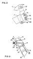
- a hydraulic drilling device which consists of a hydraulically driven hammer drill 1, which is pivotally attached to a hydraulic feed unit 10 and a hydraulic feed unit 10 with a control 14 of the hydraulic system, with cooling and rinsing water according to the invention for the drill bit 3 is used as an energy source for all movements carried out by the drill.
- a single hydraulic supply line 6 with coupling piece 4 is guided from outside the drill as an energy source for driving the feed unit 10 and for driving and flushing the drill bit 3 to the control 14 and is only a single hydraulic supply line 5 with coupling pieces 4 from the hydraulic feed unit 10 with controller 14 to the hammer drill 1, which transmits the drive power for the hammer drill 1 and the flushing air liquid for the drill bit 3.
- the hammer drill 1 with handle 2 and with inserted drill bit 3 is connected to an intermediate piece 7 of the feed unit 10 via a transmission piece 8 by hinge bolts 17, 18.
- a connecting web 23 of the transmission piece 8 is fixed via a retaining screw 16 between a damping disk 19 and a damping device 9.
- the feed and retraction movement is transmitted via a foot 15 supported on the floor by an actuating cylinder 12 with a piston acted on on both sides via a guided piston rod 11 to the housing of the control part 14 and through the intermediate piece 7 and that Transfer piece 8 passed to the hammer drill 1.
- the piston surfaces are pressurized by channels in the hollow piston rod 11 on the side towards the support foot 15 and on the other side towards the cylinder cover 13.
- a rotary valve 20 which can be rotated between two end positions via an actuating lever 22, the reversal between the feed movement and the retracting movement is carried out on the one hand by rotating over a neutral locking angle and on the other hand the hydraulic feed line 5 with energy and flushing water to the hammer drill 1 is blocked as soon as the rotary valve 20 is turned from the feed area into the neutral locking angle.
- the maximum feed rate is specified by changing a throttle point by setting the setpoint by turning a feed setting 21, which for operational reasons is preferably built on the rotary valve 20 itself.
Landscapes
- Engineering & Computer Science (AREA)
- Geology (AREA)
- Life Sciences & Earth Sciences (AREA)
- Mining & Mineral Resources (AREA)
- Physics & Mathematics (AREA)
- Environmental & Geological Engineering (AREA)
- Fluid Mechanics (AREA)
- General Life Sciences & Earth Sciences (AREA)
- Geochemistry & Mineralogy (AREA)
- Mechanical Engineering (AREA)
- Earth Drilling (AREA)
- Lubricants (AREA)
- Soil Working Implements (AREA)
- Measuring Fluid Pressure (AREA)
Claims (6)
- Appareil hydraulique de forage se composant d'un marteau perforateur (1) à commande hydraulique et d'un module hydraulique (10) d'avancement équipé d'une commande (14) du circuit hydraulique, caractérisé en ce qu'un unique conduit hydraulique d'alimentation (6) va de l'extérieur de l'appareil de forage, où il forme le transporteur d'énergie de commande du module d'avancement (10) ainsi que de commande et de rinçage d'un trépan (3), à la commande (14), et en ce qu'un unique conduit hydraulique (5) de liaison, qui est installé entre le module hydraulique d'avancement (10), y compris la commande (14), et le marteau perforateur (1), transmet l'énergie de commande du marteau perforateur (1) et le liquide de rinçage du trépan (3).
- Appareil hydraulique de forage selon la revendication 1, caractérisé en ce que la liaison pivotante entre le marteau perforateur (1) et le module d'avancement (10) comprend un amortissement (19, 9) à éléments élastiques qui est réglable de manière différente dans le sens d'avance et celui de recul.
- Appareil hydraulique de forage selon l'une des revendications 1 et 2, caractérisé en ce que la commande hydraulique (14) comprend un tiroir rotatif central (20) qui d'une part commande le mouvement d'avance et de recul du module d'avancement (10) entre deux positions extrêmes de son levier de manoeuvre (22), ainsi que l'actionnement et le non-actionnement du marteau perforateur (1) et sur lequel d'autre part un régulateur réglable de consigne (21) pour le réglage du mouvement d'avancement est placé.
- Appareil hydraulique de forage selon l'une des revendications 1 à 3, caractérisé en ce qu'aucun conduit de reflux n'est installé entre l'appareil de forage et l'alimentation hydraulique.
- Procédé d'exploitation d'un appareil hydraulique de forage selon les revendication 1 à 4, caractérisé en ce que l'eau de refroidissement et de rinçage du trépan (3) est utilisée en vecteur d'énergie pour tous les mouvements exécutés par l'appareil de forage.
- Procédé selon la revendication 5, caractérisé en ce que l'alimentation en eau énergétique et de refroidissement est effectuée en circuit ouvert.
Priority Applications (1)
| Application Number | Priority Date | Filing Date | Title |
|---|---|---|---|
| AT90810755T ATE86714T1 (de) | 1989-11-08 | 1990-10-03 | Hydraulisches bohrgeraet und verfahren zum betreiben des geraetes. |
Applications Claiming Priority (2)
| Application Number | Priority Date | Filing Date | Title |
|---|---|---|---|
| CH402789 | 1989-11-08 | ||
| CH4027/89 | 1989-11-08 |
Publications (2)
| Publication Number | Publication Date |
|---|---|
| EP0427663A1 EP0427663A1 (fr) | 1991-05-15 |
| EP0427663B1 true EP0427663B1 (fr) | 1993-03-10 |
Family
ID=4268447
Family Applications (1)
| Application Number | Title | Priority Date | Filing Date |
|---|---|---|---|
| EP90810755A Expired - Lifetime EP0427663B1 (fr) | 1989-11-08 | 1990-10-03 | Dispositif hydraulique de forage et procédé d'utilisation |
Country Status (9)
| Country | Link |
|---|---|
| US (1) | US5107933A (fr) |
| EP (1) | EP0427663B1 (fr) |
| JP (1) | JPH03161688A (fr) |
| AT (1) | ATE86714T1 (fr) |
| AU (1) | AU630750B2 (fr) |
| CA (1) | CA2029094A1 (fr) |
| DE (1) | DE59001008D1 (fr) |
| FI (1) | FI904366A7 (fr) |
| ZA (1) | ZA907692B (fr) |
Families Citing this family (15)
| Publication number | Priority date | Publication date | Assignee | Title |
|---|---|---|---|---|
| FI904366A7 (fi) * | 1989-11-08 | 1991-05-09 | Sulzer Ag | Hydraulinen porauslaite ja menetelmä sen käyttämiseksi |
| DE4433533C1 (de) * | 1994-09-20 | 1995-11-23 | Terra Ag Tiefbautechnik | Rammbohrvorrichtung |
| NO313468B1 (no) * | 2000-12-11 | 2002-10-07 | Per H Moe | Fremgangsmåte og apparat for optimalisert boring |
| DE10200309A1 (de) * | 2002-01-07 | 2003-07-17 | Hilti Ag | Vorschubstützeinrichtung für eine portable Werkzeugmaschine |
| CA2415330C (fr) * | 2002-12-19 | 2005-03-15 | Danny Morissette | Positionneur de marteau pneumatique autonome avec joint universel |
| RU2256060C1 (ru) * | 2004-08-12 | 2005-07-10 | Открытое Акционерное Общество "Акционерная Компания "Туламашзавод" (Оао "Ак "Туламашзавод") | Пневмоподатчик (варианты) |
| RU2256059C1 (ru) * | 2004-08-12 | 2005-07-10 | Открытое Акционерное Общество "Акционерная Компания "Туламашзавод" (Оао "Ак "Туламашзавод") | Пневмоподатчик (варианты) |
| US7789167B2 (en) * | 2008-04-16 | 2010-09-07 | The Boeing Company | Power assist lever arm attachment |
| DE202011100538U1 (de) * | 2011-05-11 | 2012-08-14 | Max Wild Gmbh | Bohranlage |
| CN105386735A (zh) * | 2015-12-02 | 2016-03-09 | 湖南科技大学 | 一种煤巷干式钻孔孔口集尘器液压给进装置 |
| CN105822304B (zh) * | 2016-03-23 | 2017-12-19 | 河南理工大学 | 一种沿空巷道切顶卸压定向水力切槽远程控制方法 |
| EP3645825A4 (fr) * | 2017-06-26 | 2021-04-07 | UGT Group PTY Ltd | Ensemble trépan et valve |
| CN110056318B (zh) * | 2019-04-23 | 2023-12-22 | 中工国际工程股份有限公司 | 一种盐穴储气库排卤管防堵塞装置 |
| US11051458B2 (en) * | 2019-08-07 | 2021-07-06 | John Wilson | High reaching pruning apparatus |
| CN121557155A (zh) * | 2026-01-21 | 2026-02-24 | 中国煤炭科工集团太原研究院有限公司 | 集破碎和冲击旋转钻进于一体的卧底机液压控制系统 |
Family Cites Families (13)
| Publication number | Priority date | Publication date | Assignee | Title |
|---|---|---|---|---|
| US1164496A (en) * | 1915-04-29 | 1915-12-14 | Sullivan Machinery Co | Rock-drill. |
| US2599042A (en) * | 1947-12-30 | 1952-06-03 | Clyde E Bannister | Excavating apparatus |
| US2908482A (en) * | 1952-07-16 | 1959-10-13 | Joy Mfg Co | Rock drill |
| US3132703A (en) * | 1956-05-15 | 1964-05-12 | Atlas Copco Ab | Rock drilling mechanism |
| US2964305A (en) * | 1958-11-20 | 1960-12-13 | Chicago Pneumatic Tool Co | Crust breaking apparatus |
| US3203489A (en) * | 1963-07-18 | 1965-08-31 | Thor Power Tool Co | Sinker drill |
| US4010806A (en) * | 1972-11-16 | 1977-03-08 | The Titan Manufacturing Company Proprietary Limited | Rock bolting equipment |
| US4024923A (en) * | 1972-11-16 | 1977-05-24 | Kenneth Joseph Broadbent | Rock bolting equipment |
| DE2855575C2 (de) * | 1978-12-22 | 1985-11-21 | Salzgitter Maschinen Und Anlagen Ag, 3320 Salzgitter | Hydraulische Bohrmaschine |
| AT381363B (de) * | 1983-11-08 | 1986-10-10 | Ver Edelstahlwerke Ag | Vorrichtung zum schlagenden bohren |
| JPS6255394A (ja) * | 1985-09-04 | 1987-03-11 | マツダ株式会社 | さく岩機用トンネル断面計測装置 |
| DE3708616A1 (de) * | 1987-03-17 | 1988-09-29 | Schmidt & Co Gmbh Kranz | Anker-bohreinrichtung |
| FI904366A7 (fi) * | 1989-11-08 | 1991-05-09 | Sulzer Ag | Hydraulinen porauslaite ja menetelmä sen käyttämiseksi |
-
1990
- 1990-09-04 FI FI904366A patent/FI904366A7/fi not_active Application Discontinuation
- 1990-09-26 ZA ZA907692A patent/ZA907692B/xx unknown
- 1990-10-03 EP EP90810755A patent/EP0427663B1/fr not_active Expired - Lifetime
- 1990-10-03 DE DE9090810755T patent/DE59001008D1/de not_active Expired - Fee Related
- 1990-10-03 AT AT90810755T patent/ATE86714T1/de not_active IP Right Cessation
- 1990-10-18 JP JP2280550A patent/JPH03161688A/ja active Pending
- 1990-10-25 AU AU64961/90A patent/AU630750B2/en not_active Ceased
- 1990-10-26 US US07/604,051 patent/US5107933A/en not_active Expired - Fee Related
- 1990-10-31 CA CA002029094A patent/CA2029094A1/fr not_active Abandoned
Also Published As
| Publication number | Publication date |
|---|---|
| ZA907692B (en) | 1991-07-31 |
| JPH03161688A (ja) | 1991-07-11 |
| US5107933A (en) | 1992-04-28 |
| AU6496190A (en) | 1991-05-16 |
| ATE86714T1 (de) | 1993-03-15 |
| DE59001008D1 (de) | 1993-04-15 |
| FI904366A7 (fi) | 1991-05-09 |
| FI904366A0 (fi) | 1990-09-04 |
| CA2029094A1 (fr) | 1991-05-09 |
| AU630750B2 (en) | 1992-11-05 |
| EP0427663A1 (fr) | 1991-05-15 |
Similar Documents
| Publication | Publication Date | Title |
|---|---|---|
| EP0427663B1 (fr) | Dispositif hydraulique de forage et procédé d'utilisation | |
| DE2525817A1 (de) | Steuersystem fuer hydraulikbetrieb | |
| EP1102646B1 (fr) | Dispositif de fraisage pour technique de nettoyage et d'assainissement de conduites | |
| EP0863293B1 (fr) | Méthode et dispositif pour commander un appareil d'avancement d'un appareil de forage du sol | |
| DE602004005162T2 (de) | Hydraulisches system für bergbauausrüstung und verfahren zum einstellen der leistung einer gesteinsbohrmaschine | |
| DE2952303C2 (fr) | ||
| WO1996028630A1 (fr) | Machine hydraulique de tubage a accoler a un appareil mobile de forage rotatif | |
| DE1171848B (de) | Vorrichtung und Verfahren zum Niederbringen eines Bohrloches | |
| WO2002044508A2 (fr) | Appareil pneumatique de forage de roches et procede de forage horizontal avec air comprime et fluide de forage | |
| AT394247B (de) | Gesteinsbohranlage | |
| EP0263967B1 (fr) | Dispositif de battage immergeable | |
| EP0145701B1 (fr) | Regulation d'une foreuse à percussion | |
| DE69606048T2 (de) | Mehrfach-artikulierter ausleger für arbeitsmaschine | |
| DE2554844A1 (de) | Mechanisch-hydraulische kombine fuer die gewinnung von kohle | |
| DE1458635A1 (de) | Gesteinsbohrmaschine | |
| DE3708616A1 (de) | Anker-bohreinrichtung | |
| DE3247632C1 (de) | Vorrichtung zum Herstellen eines aufwaerts gerichteten Bohrloches | |
| EP4215675A1 (fr) | Machine de construction hybride et procédé de fonctionnement d'une machine de construction hybride | |
| EP0198896B1 (fr) | Dispositif pour relier un train de barres de forage avec un tube ou element semblable | |
| DE2129052C3 (de) | Bohrstütze | |
| DE1484393B1 (de) | Bohrvorrichtung zum erweitern der sohle eines bohrlochs | |
| DE3011449A1 (de) | Verfahren und vorrichtung zum herstellen eines vertikalen oder geneigten bohrloches | |
| DE2505396C2 (de) | Bohranlage mit einer Pumpe für hydraulischen Schreitausbau als Druckerzeuger und einem hydrostatischen Drehmotor | |
| DE10146023B4 (de) | Steuerung für einen Schlagantrieb | |
| DE3301029C2 (de) | Steuerung eines mechanisch-hydraulischen Kohlenabbaugerätes |
Legal Events
| Date | Code | Title | Description |
|---|---|---|---|
| PUAI | Public reference made under article 153(3) epc to a published international application that has entered the european phase |
Free format text: ORIGINAL CODE: 0009012 |
|
| 17P | Request for examination filed |
Effective date: 19901129 |
|
| AK | Designated contracting states |
Kind code of ref document: A1 Designated state(s): AT CH DE FR GB LI SE |
|
| 17Q | First examination report despatched |
Effective date: 19920818 |
|
| GRAA | (expected) grant |
Free format text: ORIGINAL CODE: 0009210 |
|
| AK | Designated contracting states |
Kind code of ref document: B1 Designated state(s): AT CH DE FR GB LI SE |
|
| REF | Corresponds to: |
Ref document number: 86714 Country of ref document: AT Date of ref document: 19930315 Kind code of ref document: T |
|
| REF | Corresponds to: |
Ref document number: 59001008 Country of ref document: DE Date of ref document: 19930415 |
|
| GBT | Gb: translation of ep patent filed (gb section 77(6)(a)/1977) |
Effective date: 19930322 |
|
| ET | Fr: translation filed | ||
| PGFP | Annual fee paid to national office [announced via postgrant information from national office to epo] |
Ref country code: CH Payment date: 19930910 Year of fee payment: 4 |
|
| PGFP | Annual fee paid to national office [announced via postgrant information from national office to epo] |
Ref country code: DE Payment date: 19930911 Year of fee payment: 4 |
|
| PGFP | Annual fee paid to national office [announced via postgrant information from national office to epo] |
Ref country code: FR Payment date: 19930913 Year of fee payment: 4 |
|
| PGFP | Annual fee paid to national office [announced via postgrant information from national office to epo] |
Ref country code: AT Payment date: 19930914 Year of fee payment: 4 |
|
| PGFP | Annual fee paid to national office [announced via postgrant information from national office to epo] |
Ref country code: SE Payment date: 19930915 Year of fee payment: 4 |
|
| PLBE | No opposition filed within time limit |
Free format text: ORIGINAL CODE: 0009261 |
|
| STAA | Information on the status of an ep patent application or granted ep patent |
Free format text: STATUS: NO OPPOSITION FILED WITHIN TIME LIMIT |
|
| 26N | No opposition filed | ||
| PG25 | Lapsed in a contracting state [announced via postgrant information from national office to epo] |
Ref country code: GB Effective date: 19941003 Ref country code: AT Effective date: 19941003 |
|
| PG25 | Lapsed in a contracting state [announced via postgrant information from national office to epo] |
Ref country code: SE Effective date: 19941004 |
|
| PG25 | Lapsed in a contracting state [announced via postgrant information from national office to epo] |
Ref country code: LI Effective date: 19941031 Ref country code: CH Effective date: 19941031 |
|
| EAL | Se: european patent in force in sweden |
Ref document number: 90810755.0 |
|
| GBPC | Gb: european patent ceased through non-payment of renewal fee |
Effective date: 19941003 |
|
| PG25 | Lapsed in a contracting state [announced via postgrant information from national office to epo] |
Ref country code: FR Effective date: 19950630 |
|
| REG | Reference to a national code |
Ref country code: CH Ref legal event code: PL |
|
| PG25 | Lapsed in a contracting state [announced via postgrant information from national office to epo] |
Ref country code: DE Effective date: 19950701 |
|
| EUG | Se: european patent has lapsed |
Ref document number: 90810755.0 |
|
| REG | Reference to a national code |
Ref country code: FR Ref legal event code: ST |