EP0427953A2 - Einrichtung und Methode zur Veränderung von Sprechgeschwindigkeit - Google Patents
Einrichtung und Methode zur Veränderung von Sprechgeschwindigkeit Download PDFInfo
- Publication number
- EP0427953A2 EP0427953A2 EP90119083A EP90119083A EP0427953A2 EP 0427953 A2 EP0427953 A2 EP 0427953A2 EP 90119083 A EP90119083 A EP 90119083A EP 90119083 A EP90119083 A EP 90119083A EP 0427953 A2 EP0427953 A2 EP 0427953A2
- Authority
- EP
- European Patent Office
- Prior art keywords
- signal
- time
- length
- correlation function
- point
- Prior art date
- Legal status (The legal status is an assumption and is not a legal conclusion. Google has not performed a legal analysis and makes no representation as to the accuracy of the status listed.)
- Granted
Links
Images









Classifications
-
- G—PHYSICS
- G10—MUSICAL INSTRUMENTS; ACOUSTICS
- G10L—SPEECH ANALYSIS TECHNIQUES OR SPEECH SYNTHESIS; SPEECH RECOGNITION; SPEECH OR VOICE PROCESSING TECHNIQUES; SPEECH OR AUDIO CODING OR DECODING
- G10L21/00—Speech or voice signal processing techniques to produce another audible or non-audible signal, e.g. visual or tactile, in order to modify its quality or its intelligibility
- G10L21/04—Time compression or expansion
Definitions
- the present invention relates to an apparatus for and a method of performing a speech rate modification in which only the time duration of a speech is changed without altering the fundamental frequency components of the speech signal.
- speech rate modification apparatus in order to perform a speed-up listening or a slow-down listening of speech signals recorded on audio tapes or the likes, speech rate modification apparatus have been utilized.
- This speech rate modification apparatus is comprised of a variable delay line, a ramp level and amplitude changer, a blanking circuit, a blanking pulse generator, and a ramp pulse-train generator.
- the input signal is first written into the variable delay line.
- the ramp pulse-train generator controls the ramp level and amplitude changer and the blanking pulse generator corresponding to a time-scale modification ratio.
- the level and amplitude changer performs the read-out operation of signals from the variable delay line with a speed which is different from that at the time of write-in operation depending on the time-axis modification ratio.
- the reproduction rate of a tape when the reproduction rate of a tape is increased, the read-out operation of the data from a memory is made slower than the write-in operation to the memory in order to restore raised tone (frequencies) to normal one; whereas when the reproduction rate of a tape is decreased, the read-out operation of the data from the memory is made faster than the write-in operation of the data to the memory in order to restore lowered tone to normal tone.
- the blanking circuit applies the muting action on the output of the variable delay line.
- Purpose of the present invention is to offer a speech rate modification apparatus which is capable of issuing a speech voice having an ample naturalness with less data drop-offs.
- a speech rate modification apparatus of the present invention comprises a correlator for computing a correlation function between different segments of input signal, a multiplier for controlling the amplitude of the signal, an adder for carrying out the addition calculation of signals at a time point at which the correlation function takes a largest value within a time-length of unitary segment based on the output from the above-mentioned correlator, and a selection circuit for switching over between the input signal and the output of the above-mentioned adder.
- the discontinuities of signal amplitude or the drop-offs of data become less, and also in consequence of the addition calculation of signals by the correlator and the adder at a time point at which the correlation function takes a largest value, discontinuities in phase also become less. And furthermore, in consequence of the control of segments by which the input signal is directly issued through selection circuits, wide range of desired time-scale modification ratios are obtainable.
- the present invention is to offer a speech rate modification apparatus which is capable of giving a speech voice having an ample naturalness with less discontinuities in signal amplitude and phase and also with less data drop-offs and also which can be realized with a simple hardware.
- FIG.1 is a block diagram of a speech rate modification apparatus in the present apparatus-embodiment.
- numeral 11 is an A/D converter for converting input voice signal to digitized voice signal.
- a buffer 12 is for temporarily storing the digitized voice signal.
- a demultiplexer 14 switches to deliver the digitized voice signal to a first memory 15, to a second memory 16, and to a multiplexer 22, being controlled by a rate control circuit 13.
- a correlator 17 is for computing correlation function between outputs of the first memory 15 and the second memory 16. Output terminals of the correlator 17 are connected to the rate control circuit 13, to an adder 21 and to a window function generator 18.
- a first multiplier 19 and a second multiplier 20 are for multiplying output of the window function generator 15 on outputs of the first memory 15 and of the second memory 16, respectively.
- the output terminals of the multipliers 19 and 20 are connected to the adder 21 which adds outputs to each other being controlled by the output of the correlator 17.
- the multiplexer 22 is for combining outputs from the adder 21 and the demultiplexer 14 under control of the rate control circuit 13.
- a D/A converter 23 is for converting the combined digital signal to an analog output signal.
- the input signal is converted into a digital signal by the A/D converter 11 and written into the buffer 12.
- the rate control circuit 13 controls the demultiplexer 14 in accordance with a given time-scale modification ratio to supply the data in the buffer 12 to the first memory 15 and the second memory 16, and also to the multiplexer 22.
- correlation functions between the contents of the first memory 15 and that of the second memory 16 are computed by the correlator 17, and the information of these correlation computation is supplied to the rate control circuit 13, the window function generator 18, and the adder 21.
- the window function generator 18 generates a first window function which gradually increases or gradually decreases, based on the information from the correlator 17 and on a given time-scale modification ratio, to supply it to the first multiplier 19.
- the window function generator 18 also issues a second window function which is complementary to the above-mentioned first window function, to supply it to the second multiplier 20.
- the first multiplier 19 performs a multiplication calculation between the contents of the first memory 15 and the first window function issued from the window function generator 18; whereas the second multiplier 20 performs a multiplication calculation between the contents of the second memory 16 and the second window function issued also from the window function generator 18.
- the adder 21 performs an addition calculation between these windowed outputs from the first multiplier 19 and from the second multiplier 20 after displacing their mutual position making a relative delay so that the computed correlation function takes a largest value within a time-length of unitary segment, based on the information from the correlator 17.
- the adder 21 supplies the sum output to the multiplexer 22. Then, the multiplexer 22 selects the output of the adder 21 and the output of the demultiplexer 14 and supplies the selected result to the D/A converter 23, which converts the resultant digital signal to an analog signal.
- the contents of the first memory 15 and the contents of the second memory 16 are multiplied respectively by paired window functions.
- These paired window functions are complementary to each other, one being a gradually increasing window function and the other being a gradually decreasing window function, both generated from the window function generator 18.
- those windowed outputs from respective multipliers are added to each other by the adder 21, thus making a digitized speech voice having an ample naturalness with less discontinuities in the signal amplitude and also with relatively small data drop-offs.
- the correlator 17 computes a correlation function between the contents of the first memory 15 and the contents of the second memory 16.
- the adder 21 performs an addition calculation between the outputs from the first multiplier 19 and from the second multiplier 20 after displacing their mutual position to make delay so that the computed correlation function takes a largest value within a time-length of unitary segment.
- a high quality speech voice signal with less discontinuities in the signal phase can be obtained.
- the length of segments in which the input signal is directly issued is controlled by the action of the rate control circuit 13, the demultiplexer 14 and the multiplexer 22. Thereby, time-scale modification ratio can easily be changed.
- the present invention is to offer a method of speech rate modification which is capable of giving a speech voice having an ample naturalness with less discontinuities in signal amplitude and phase and also with less data drop-offs for a range of the time-scale modification ratio of ⁇ ⁇ 1.0.
- time-scale modification ratio a is defined as
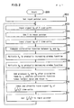
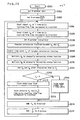
- FIG .2 is a flow chart representing a speech rate modification method in the present embodiment. Its operation is elucidated below.
- an input pointer is reset (step 202). Then, a signal X A having a time-length as long as T time-units starting from a time point designated by this input pointer is inputted from the demultiplexer 14 to the first memory 15 (step 203). Then, T is added to the input pointer to update it (step 204). Next, a signal X B having thus the same time-length as long as T time-units starting from a time point designated by this updated input pointer is inputted from the demultiplexer 14 to the second memory 16 (step 205). Then a correlation function between X A and X B is computed (step 206).
- X A is multiplied by a window of a gradually increasing function (step 207).
- X B is multiplied by a window of a gradually decreasing function (step 208).
- these windowed X A and X B are displaced to each other by a time units T c (as shown also in FIG. 3) so that the correlation function between X A and X B takes a largest value within a time-length of unitary segment and they are added, issuing the added result (step 209).
- a signal X C which has a time-length of T/( ⁇ -1) time-units from a time point designated by the updated input pointer, is inputted from the demultiplexer 14 and directly issued to the multiplexer 22 (step 210). Then T/( ⁇ -1) is added to the input pointer to update it (step 211). Then, step returns to the step 203.
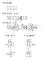
- FIG.3 schematically illustrates actual exemplary cases, wherein the horizontal direction corresponds to the time lapse and the vertical heights corresponds to the amplitude level of voice signal.
- FIG.3(a) schematically shows a succession of segments, designated by 1, 2, 3, original voice signal on which speech rate modification process is to be carried out.
- FIGs.3, (b) and (c) schematically represent embodiments that the time-scale modification ratios ⁇ are 2.0 and 3.0, respectively.
- f stands for the fore part of a segment, while h stands for the hind part thereof.
- FIGs.3, (d) and (e) schematically illustrate examples of individual detailed process of the addition calculation.
- FIG.3(d) illustrates a case of addition calculation designated by D in FIG.3(b) and FIG.3(c), wherein the addition calculation is done under a condition that the correlation function takes a largest value when X B is displaced to the positive side by T c time-units with respect to X A , resulting in extension of arise time sections outside the leading and rear edges of their overlapping time interval.
- FIG. 3(e) illustrates another case of addition calculation designated by E in FIG.3(b) and in FIG.3(c), wherein the addition calculation for the same condition is done when X B is displaced to the negative side by T c time-units with respect to X A .
- FIGs. 3(d) illustrates a case of addition calculation designated by D in FIG.3(b) and FIG.3(c), wherein the addition calculation is done under a condition that the correlation function takes a largest value when X B is displaced to the positive side by T c time-units with respect to X A , resulting in
- time intervals designated by D which correspond to the time interval D of FIG.3(d).
- time sections extending outside the overlapping time interval may overlap also to adjacent time intervals and hence it is necessary to perform the amplitude adjustments also in those adjacent time intervals.
- signals X A and X B are multiplied respectively by window functions which are complementary to each other, one being a gradually increasing window function and the other being a gradually decreasing window function. And a signal obtained by adding these windowed signals is inserted at a time point corresponding to the beginning of the input signal part X B , and this process is repeated.
- a speech voice having an ample naturalness with less discontinuities in signal amplitude and also with less data drop-offs can be issued for a range of the time-scale modification ratio of ⁇ ⁇ 1.0.
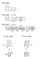
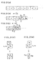
- FIG .4 schematically illustrates modified exemplary cases obtained by modifying the above-mentioned embodiment.
- FIG. 4(a) schematically shows a succession of segments 1, 2, 3, Vietnamese each having a time-length of T time-units of an original voice signal on which the speech rate modification process is to be carried out.
- FIG.4(b) and FIG. 4(c) schematically represent embodiments that the time-scale modification ratios ⁇ are 2.0 and 3.0, respectively, and
- FIG. 4(d) and FIG.4(e) schematically illustrate examples of detailed individual process of the addition calculation.
- FIG. 4(d) illustrates a case of addition calculation designated by D in FIG.
- FIG. 4(e) illustrates another case of addition calculation, designated by E in FIG. 4(b) and FIG.4(c), wherein the addition calculation for the same condition is done when X B is displaced to the negative side by T c time-units with respect to X A .
- time intervals designated by D which correspond to the time interval D of FIG.4(d).
- This modified method can be realized by changing the window function. This modified method enables realizing a simplification of process described above without suffering a degradation in the recognizability of the speech voice.
- the present embodiment is to offer a method of speech rate modification which is capable of giving a speech voice having an ample naturalness with less discontinuities in signal amplitude and phase and also with less data drop-offs for a range of the time-scale modification ratio of 0.5 ⁇ ⁇ ⁇ 1.0.
- FIG.5 shows a flow chart representing a speech rate modification method in the present embodiment, and the same hardware as shown in FIG. 1 is used. Its operation is elucidated below.
- an input pointer is reset (step 502). Then, a signal X A having a time-length as long as T time-units starting from a time point designated by this input pointer is inputted (step 503). Then, T is added to the input pointer to update it (step 504). Next, a signal X B having thus the same time-length as long as T time-units starting from a time point designated by this updated input pointer is inputted (step 505). And T is added to the input pointer to update it (step 506). Then a correlation function between X A and X B is computed (step 507). Based on this correlation function thus obtained, X A is multiplied by a window of a gradually decreasing function (step 508).
- X B is multiplied by a window of a gradually increasing function(step 509). Then based also on the correlation obtained, these windowed X A and X B are added to each other after they are mutually displaced at a time point at which the correlation function takes a largest value within a time-length of unitary segment and the added result is issued (step 510).
- a signal X C having a time-length of (2 ⁇ -1)T/( ⁇ -1) time-units starting from a time point designated by the updated input pointer is inputted and directly issued (step 511). Then (2 ⁇ -1)T/( ⁇ -1) is added to the input pointer to update it (step 512). Then, step returns to the step 503.
- FIG.6 schematically represents actual exemplary cases, wherein FIG.6(a) schematically shows a succession of segments each having a time-length of T time-units of original voice signals on which speech rate modification process is to be carried out, FIG.6(b) and FIG.6(c) schematically represent embodiments that the time-scale modification ratios ⁇ are 2/3 and 0.5, respectively.
- FIG.6(d) and FIG.6(e) schematically illustrate examples of individual detailed process of the addition calculation with mutual;
- FIG.6(d) illustrates a case of addition calculation designated by D in FIG.6(b) and FIG.6(c), wherein the addition calculation under the condition that the correlation function takes a largest value when X B is displaced to the positive side by T c time-units with respect to X A .
- FIG.6(e) illustrates another case of addition calculation, designated by E in FIG.6(b) and FIG.6(c), wherein the addition calculation is done for the same condition is done when X B is displaced to the negative side by T c time-units with respect to X A .
- time intervals designated by E which correspond to the time interval E of FIG.6(e).
- time sections extending outside the overlapping time interval may overlap also to adjacent time intervals and hence it is necessary to perform the amplitude adjustments also in those adjacent time intervals.
- signals X A and X B are multiplied respectively by window functions which are complementary to each other, one being a gradually decreasing window function and the other being a gradually increasing window function. And a signal obtained by adding these windowed signals is issued and then the signal X C is issued, and this process is repeated.
- a speech voice having an ample naturalness with less discontinuities in signal amplitude and also with less data drop-offs can be issued for a range of the time-scale modification ratio of 0.5 ⁇ ⁇ ⁇ 1.0.
- FIG .7 schematically illustrates modified exemplary cases obtained by modifying the above-mentioned embodiment, wherein FIG. 7(a) schematically shows a succession of segments each having a time-length of T time-units of an original voice signal on which the speech rate modification process is to be carried out, FIG. 7(b) and FIG. 7(c) schematically represent embodiments that the time-scale modification ratios ⁇ are 2/3 and 0.5, respectively. And, FIG. 7(d) and FIG 7(e) schematically illustrate examples of detailed individual process of the addition calculation. FIG. 7(d) illustrates a case of addition calculation designated by D in FIG. 7(b) and FIG.
- FIG. 7(e) illustrates another case of addition calculation designated by E in FIG.7(b) and FIG.7(c), wherein the addition calculation for the same condition is done when X B is displaced to the negative side by T c time-units with respect to X A and time sections extending outside the leading and rear edges of the overlapping time interval are discarded.
- time intervals designated by E which correspond to the time interval E of FIG.7(e).
- This modified method can be realized by changing the window function. This modified method enables realizing a simplification of process described above without suffering a degradation in the recognizability of the speech voice.
- the present embodiment is to offer a method of speech rate modification which is capable of giving a speech voice having an ample naturalness with less discontinuities in signal amplitude and phase for a range of the time-scale modification ratio of ⁇ ⁇ 0.5.
- FIG 8 shows a flow chart representing a speech rate modification method in the present embodiment, and the same hardware as shown in FIg.1 is used. Its operation is elucidated below.
- an input pointer is reset (step 802). Then, a signal X A having a time-length as long as T time-units starting from a time point designated by this input pointer is inputted (step 803). Then, (1- ⁇ )T/ ⁇ is added to the input pointer to update it (step 804). Next, a signal X B having the same time-length as long as T time-units starting from a time point designated by this updated input pointer is inputted (step 805). And T is added to the input pointer to update (step 806). Then a correlation function between X A and X B is computed (step 807).
- X A is multiplied by a window of a gradually decreasing function (step 808).
- X B is multiplied by a window of a gradually increasing function (step 809).
- these windowed X A and X B are added to each other after they are displaced at a point at which the correlation function between X A and X B takes a largest value within a time-length of unitary segment and the added result is issued (step 810). Then the step returns to the step 803.
- FIG.9 schematically represents actual exemplary cases, wherein FIG.9(a) schematically shows a succession of segments each having a time-length of T time-units of original voice signals on which speech rate modification process is to be carried out, FIGs.9(b) and (c) schematically represent embodiments that the time-scale modification ratios ⁇ are 1/3 and 1/4, respectively, and FIGs.9(d) and (e) schematically illustrate examples of individual detailed process of the addition calculation with mutual; FIG. 9(d) illustrates a case of addition calculation designated by D in FIG.9(b) and FIG.9(c), wherein the addition calculation under the condition that the correlation function takes a largest value when X B is displaced to the positive side by T c time-units with respect to X A .
- FIG. 9(e) illustrates another case of addition calculation designated by E in FIG.9(b) and FIG.9(c), wherein the addition calculation is done for the same condition when X B is displaced to the negative side by T c time-units with respect to X A .
- time intervals designated by E which correspond to the time interval E of FIG. 9(e).
- time sections extending outside the overlapping time interval may overlap also to adjacent time intervals and hence it is necessary to perform the amplitude adjustments also in those adjacent time intervals.
- signals X A and X B are multiplied respectively by window functions which are complementary to each other, one being a gradually increasing window function and the other being a gradually decreasing window function. And a signal obtained by adding these windowed signals is issued. And this process is repeated.
- a speech voice having an ample naturalness with less discontinuities in signal amplitude can be issued for a range of the time-scale modification ratio of ⁇ ⁇ 0.5.
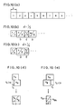
- FIG.10 schematically illustrates modified exemplary cases obtained by modifying the above-mentioned embodiment, wherein FIG.10(a) schematically shows a succession of segments each having a time-length of T time-units of an original voice signal on which the speech rate modification process is to be carried out, FIGs.10(b) and (c) schematically represent embodiments that the the time-scale modification ratios ⁇ are 1/3 and 1/4, respectively, and FIGs.10(d) and (e) schematically illustrate examples of detailed individual process of the addition calculation.
- FIG.10(d) illustrates a case of addition calculation designated by D in FIG.10(b) and FIG.10(c), wherein the addition calculation is done under a condition that the correlation function takes a largest value when X B is displaced to the positive side by T c time-units with respect to X A .
- FIG.10(e) illustrates another case of addition calculation designated by E in FIG.10(b) and FIG.10(c), wherein the addition calculation for the same condition is done when X B is displaced to the negative side by T c time-units with respect to X A , and time sections extending outside the leading and rear edges of the overlapping time interval are discarded.
- the present embodiment is to offer a method of speech rate modification which is capable of giving a speech voice having an ample naturalness with less discontinuities in signal amplitude and phase and also with less data drop-offs also for a range of the time-scale modification ratio of ⁇ ⁇ 0.5.
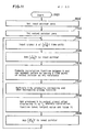
- FIG. 11 shows a flow chart representing a speech rate modification method in the present method-embodiment, and the same hardware as shown in FIG.1 is used. Its operation is elucidated below.
- an input pointer is reset (step 1102).
- an output pointer is reset (step 1103).
- a signal X having a time-length as long as T/(1- ⁇ ) time-units starting from a time point designated by this input pointer is inputted (step 1104).
- T/(1- ⁇ ) is added to the input pointer to update it (step 1105).
- a correlation function between X and the output of one segment before is computed by having a time point of the output pointer as its reference (step 1106). Based on this correlation function thus obtained, X is multiplied by a window of a gradually increasing function at its leading-half part and a gradually decreasing function at its rear-half part (step 1107).
- this windowed X is added to the output signal so that the correlation function takes a largest value within a time-length of unitary segment and the added result is issued (1108). Then ⁇ T/(1- ⁇ ) is added to the output pointer to update it (step 1109). Next, step returns to the step 1104.
- FIG. 12 schematically represents actual exemplary cases, wherein the time-scale modification ratios ⁇ are 1/3 and 1/4.
- X is multiplied by a window lfunction which increases gradually at its leading-half part and a gradually decreasing function at its rear-half part on X. Then this windowed X is added on the output signal and issued. And this process is repeated.
- a speech voice having an ample naturalness with less discontinuities in signal amplitude and also with less data drop-offs can be issued for a range of the time-scale modification ratio of ⁇ ⁇ 0.5.
- the present invention is to offer a speech rate modification apparatus which is capable of giving a speech voice having an ample naturalness with less discontinuities in signal amplitude and phase and also with less data drop-offs and also which can be realized with a simple hardware.
- FIG.13 is a block diagram of the improved speech rate modification apparatus in the present embodiment.
- numeral 11 is an A/D converter for converting input voice signal to digitized voice signal.
- a buffer 12 is for temporarily storing the digitized voice signal.
- a demultiplexer 14 switches to deliver the digitized voice signal to a first memory 15, to a second memory 16, and to a multiplexer 22, being controlled by a rate control circuit 13.
- a correlator 17 is for computing correlation function between outputs of the first memory 15 and the second memory 16. Output terminals of the correlator 17 are connected to a third multiplier 26, which multiplies the output of a weighting function generator 25 on the output of the correlator 17.
- the weighting function generator 25 generate weighting functions depending upon the output of a time-scale modification ratio detector 24, which detects the difference between the number of data supplied to the demultiplexer 14 and the number of data issued from the multiplexer 22 under the control of the rate control circuit 13.
- the output of the third multiplier 26 is supplied to the rate control circuit 13, the window function generator 18, and an adder 21.
- a first multiplier 19 and a second multiplier 20 are for multiplying output of the window function generator 18 on outputs of the first memory 15 and of the second memory 16, respectively.
- the output terminals of the multipliers 19 and 20 are connected to the adder 21 which adds outputs to each other being controlled by the output of the third multiplier 26.
- the multiplexer 22 is for combining outputs from the adder 21 and the demultiplexer 14 under control of the rate control circuit 13.
- a D/A converter 23 is for converting the combined digital signal to an analog output signal.
- the input signal is converted into a digital signal by the A/D converter 11 and written into the buffer 12.
- the rate control circuit 13 controls the demultiplexer 14 in accordance with a given time-scale modification ratio to supply the data in the buffer 12 to the first memory 15 and the second memory 16, and also to the multiplexer 22.
- the time-scale modification ratio detector 24 detects a time-scale modification ratio presently being processed by judging from the number of data supplied to the demultiplexer 14 and the number of data issued from the multiplexer 22. And monitoring the deviation from the target time-scale modification ratio which is set in the rate control circuit 13, information thus obtained is issued to the weighting function generator 25.
- the weighting function generator 25 corrects the weighting function to be issued in a manner that the time-scale modification ratio of speech voice data presently being processed does not deviate largely corresponding to an amount of the deviation with respect to the target time-scale modification ratio obtained from the time-scale modification ratio detector 24. Then, a correlation function between the contents of the first memory 15 and that of the second memory 16 is computed by the correlator 17. The third multiplier 26 performs a multiplication calculation between the output of the correlator 17 and the output of the weighting function generator 25. Then the information thus obtained is supplied to the rate control circuit 13, the window function generator 18, and the adder 21.
- the window function generator 18 supplies a window function to the first multiplier 19 and the second multiplier 20 based on the information from the third multiplier 26.
- the first multiplier 19 performs a multiplication calculation between the contents of the first memory 15 and the first window function issued from the window function generator 18, whereas the second multiplier 20 performs a multiplication calculation between the contents of the second memory 16 and the second window function issued also from the window function generator 18.
- the adder 21 performs an addition calculation between the output of the first multiplier 19 and the output of the second multiplier 20 after displacing their mutual position so that the weighted correlation function takes a largest value within a time-length of unitary segment based on the information from the third multiplier 26 and supplies its output to the multiplexer 22.
- the multiplexer 22 selects the output of the adder 21 and the output of the multiplexer 14 and supplies the selected result to the D/A converter 23, which converts the resultant digital signal to an analog signal.
- FIG.14 and FIG.15 show examples of weighting functions issued from the weighting function generator 25.
- each abscissa represents mutual delay between two segments whereon the correlation function is computed.
- FIG. 14 shows a weighting function by which the largest value of the correlation function is searched only at a side wherein the deviation is made less.
- FIG. 14(a) shows a case that the deviation from the target time-scale modification ratio increases when the largest value of the correlation function is present on the negative side.
- FIG.14(b) shows a case that the presently processed time-scale modification ratio does not deviate from the target time-scale modification ratio.
- FIG. 14(c) shows a case that the deviation from the target time-scale modification ratio increases when the largest value of the correlation function is present at the positive side.
- FIG. 15 shows a weighting function which searches, in case that the presently processed time-scale modification ratio deviates from the target time-scale modification ratio, the largest value of the correlation function by putting a weight on the side on which the deviation is made less.
- FIG.15(a) shows a case that the deviation from the target time-scale modification ratio increases when the largest value of the correlation function is present on the negative side.
- FIG.15(b) shows a case that the presently processed time-scale modification ratio does not deviate from the target time-scale modification ratio.
- FIG.15(c) shows a case that the deviation from the target time-scale modification ratio increases when the largest value of the correlation function is present on the positive side.
- the contents of the first memory 15 and the contents of the second memory 16 are multiplied respectively by a window function generated from the window function generator 18. Then those windowed outputs from respective multipliers are added to each other by the adder 21.
- the correlator 17 computes a correlation function between the contents of the first memory 15 and the contents of the second memory 16.
- the adder 21 performs an addition calculation between the outputs from the first multiplier 19 and from the second multiplier 20 after displacing their mutual position so that the correlation function between the output of the first multiplier 19 and the output of the second multiplier 20 takes a largest value within a time-length of unitary segment. Thus, thereby the discontinuities in the phase of the signal is reduced.
- the time-scale modification ratio actually obtained may deviates from the target time-scale modification ratio. Then, according to the configuration of FIG. 13, the time-scale modification ratio actually being processed is detected by the time-scale modification ratio detector 24, and thereby the deviation from the target value is monitored. Responding to the deviation, the weighting function generator 25 changes the weighting function and issues it.
- the deviation from the target time-scale modification ratio can easily be reduced and and also a time position at which the correlation function takes a largest value within a time-length of unitary segment can be found. Thereby a high quality processed speech voice with less time scale fluctuations can be obtained with a desired time-scale modification ratio.
- the present embodiment is to offer a method of speech rate modification which is capable of giving a speech voice having an ample naturalness with less discontinuities in signal amplitude and phase and also with less data drop-offs for a range of the time-scale modification ratio of ⁇ ⁇ 1.0.
- FIG. 16 shows a flow chart representing a speech rate modification method in the present embodiment. Its operation is elucidated below.
- an A-pointer is set to be 0 (step 1602), while a B-pointer is set to be T (step 1603).
- a signal X A having a time-length as long as T time-units starting from a time point designated by the A-pointer is inputted (step 1604).
- a signal X B having a time interval as long as T time-units starting from a time point designated by the B-pointer is inputted (step 1605).
- the B-pointer is updated by inputting a number obtained by adding T on the contents of the A-pointer (step 1606).
- a correlation function between X A and X B is computed (step 1607).
- a time point T c (which corresponds to a time point displaced by T c from the time point when two segments completely overlap.) at which the correlation function takes its largest value within a time-length of one unitary segment is searched (step 1608).
- X A is multiplied by a window of a gradually increasing function (step 1609).
- X B is multiplied by a window of a gradually decreasing function (step 1610).
- these windowed X A and X B are added to each other after they are mutually displaced at a time point at which the correlation function takes a largest value within one unitary segment (step 1611).
- step 1613 added signal is all issued (step 1613), further a signal X C of a time-length as long as T/( ⁇ -1)+T c time-units starting from a time point designated by the B-pointer is directly issued (step 1615).
- ⁇ T/( ⁇ -1) is less than T-T C the added signal is issued only for a time-length of ⁇ T/( ⁇ -1) time-units (step 1614).
- T/( ⁇ -1)+T c is added to the B-pointer to update it (step 1616).
- T/( ⁇ -1) is added to the A-pointer to update it (step 1617). Then, step returns to the step 1604.
- FIG.17 schematically represents actual exemplary cases, wherein FIG.17(a) schematically shows a succession of segments each having a time-length of T time-units of original voice signals on which speech rate modification process is to be carried out, FIG.17(b) and FIG.17(c) schematically represent embodiments that the time-scale modification ratios ⁇ are 2.0 and 3.0, respectively, and FIG.17(d) and FIG.17(e) schematically illustrate examples of individual detailed process of the mutual addition calculation.
- FIG.17(d) illustrates a case of addition calculation designated by D in FIG.17(b) and FIG.17(c), wherein the addition calculation under the condition that the correlation function takes a largest value when X B is displaced to the positive side by T c time-units with respect to X A
- FIG. 17(e) illustrates another case of addition calculation designated by E in FIG. 17(b) and FIG.17(c), wherein the addition calculation is done for the same condition when X B is displaced to the negative side by T c time-units with respect to X A
- there are time intervals designated by D which correspond to the time interval D of FIG.17(d). In these time intervals, time sections extending outside the overlapping time interval may overlap also to adjacent time intervals and hence it is necessary to perform the amplitude adjustments also in those adjacent time intervals.
- signals X A and X B are multiplied respectively by window functions which are complementary to each other, one being a gradually increasing window function and the other being a gradually decreasing window function. And a signal obtained by adding these windowed signals is issued, and a signal X C subsequent to X A is issued, and these process is repeated.
- a speech voice having an ample naturalness with less discontinuities in signal amplitude and also with less data drop-offs can be issued for a range of the time-scale modification ratio of ⁇ ⁇ 1.0.
- FIG.18 schematically illustrates modified exemplary cases obtained by modifying the above-mentioned embodiment, wherein FIG. 18(a) schematically shows a succession of segments each having a time-length of T time-units of an original voice signal on which the speech rate modification process is to be carried out, FIG.18(b) and FIG.18(c) schematically represent embodiments that the the time-scale modification ratios a are 2.0 and 3.0, respectively, and FIGs.18(d) and (e) schematically illustrate examples of detailed individual process of the addition calculation.
- FIG. 18(a) schematically shows a succession of segments each having a time-length of T time-units of an original voice signal on which the speech rate modification process is to be carried out
- FIG.18(b) and FIG.18(c) schematically represent embodiments that the time-scale modification ratios a are 2.0 and 3.0, respectively
- FIGs.18(d) and (e) schematically illustrate examples of detailed individual process of the addition calculation.
- FIG. 18(a) schematically shows
- FIG.18(d) illustrates a case of addition calculation designated by D in FIG.18(b) and FIG.18(c), wherein the addition calculation is done under a condition that the correlation function takes a largest value when X B is displaced to the positive side by T c time-units with respect to X A and time sections extending outside the leading and rear edges of the overlapping tie interval are discarded.
- FIG.18(e) illustrates another case of addition calculation designated by E in FIG.18(b) and FIG.18(c), wherein the addition calculation for the same condition is done when X B is displaced to the negative side by T c time-units with respect to X A .
- the present embodiment is to offer a method of speech rate modification which is capable of giving a speech voice having an ample naturalness with less discontinuities in signal amplitude and phase and also with less data drop-offs also for a range of the time-scale modification ratio of 0.5 ⁇ ⁇ ⁇ 1.0.
- FIG. 19 shows a flow chart representing a speech rate modification method in the present embodiment, and the same hardware as shown in FIG.1 is used. Its operation is elucidated below.
- an A-pointer is set to be 0 (step 1902), while a B-pointer is set to be T (step 1903). Then, a signal X A having a time-length as long as T time-units starting from a time point designated by the A-pointer is inputted (step 1904). And, a signal X B having a time interval as long as T time-units starting from a time point designated by the B-pointer is inputted (step 1905). Then, the A-pointer is updated to be a number obtained by adding T on the contents of the B-pointer (step 1906).
- a correlation function between X A and X B is computed (step 1907).
- a time point T c at which the correlation function takes its largest value in a time-length of one unitary segment is searched (step 1908).
- X A is multiplied by a window of a gradually decreasing function (step 1909).
- X B is multiplied by a window of a gradually increasing function is multiplied on X B (step 1910).
- these windowed X A and X B are added to each other after they are mutually displaced at a time point at which the correlation function takes a largest value within a time-length of one unitary segment (step 1911).
- step 1913 added signal is all issued (step 1913). Further a signal X C of a time interval as long as (2 ⁇ -1)T/(1- ⁇ )-T c time-units starting from a time point designated by the A-pointer is directly issued (step 1915). On the other hand, in case that ⁇ T/(1- ⁇ ) is less than T+T c , the added signal is issued only for a time-length of ⁇ T/(1- ⁇ ) time-units (step 1914). Next, (2 ⁇ -1)T/(1- ⁇ )-T c is added to the A-pointer to update it (step 1916). And T/(1- ⁇ ) is added to the B-pointer to update it (step 1917). Then, step returns to the step 1904.
- FIG.20 schematically represents actual exemplary cases, wherein FIG.20(a) schematically shows a succession of segments each having a time-length of T time-units of original voice signals on which speech rate modification process is to be carried out, FIG.20(b) and FIG.20(c) schematically represent embodiments that the time-scale modification ratios a are 2/3 and 0.5, respectively, and FIG.20(d) and FIG.20(e) schematically illustrate examples of individual detailed process of the mutual addition calculation.
- FIG.20(d) illustrates a case of addition calculation, designated by D in FIG.20(b) and FIG.20(c), wherein the addition calculation under the condition that the correlation function takes a largest value when X B is displaced to the positive side by T c time-units with respect to X A .
- FIG.20(e) illustrates another case of addition calculation designated by E in FIG.20(b) and FIG.20(c), wherein the addition calculation is done for the same condition when X B is displaced to the negative side by T c time-units with respect to X A .
- there are time intervals designated by E which correspond to the time interval E of FIG.20(e). In these time intervals, time sections extending outside the overlapping time interval may overlap also to adjacent time intervals and hence it is necessary to perform the amplitude adjustments also in those adjacent time intervals.
- signals X A and X B are multiplied respectively by window functions which are complementary to each other, one being a gradually increasing window function and the other being a gradually decreasing window function. And a signal obtained by adding these windowed signals is issued, and a signal X C subsequent to X B is issued, and these process is repeated.
- a speech voice having an ample naturalness with less discontinuities in signal amplitude and also with less data drop-offs can be issued for a range of the time-scale modification ratio of 0.5 ⁇ ⁇ ⁇ 1.0.
- FIG. 21 schematically illustrates modified exemplary cases obtained by modifying the above-mentioned embodiment, wherein FIG.21(a) schematically shows a succession of segments each having a time-length of T time-units of an original voice signal on which the speech rate modification process is to be carried out, FIG.21(b) and FIG.21(c) schematically represent embodiments that the time-scale modification ratios ⁇ are 2/3 and 0.5, respectively, and FIG.21(d) and FIG.21(e) schematically illustrate examples of detailed individual process of the addition calculation.
- FIG.21(d) illustrates a case of addition calculation designated by D in FIG.21(b) and FIG.21(c), wherein the addition calculation is done under a condition that the correlation function takes a largest value when X B is displaced to the positive side by T c time-units with respect to X A .
- FIG.21(e) illustrates another case of addition calculation, designated by E in FIG.21(b) and FIG.21(c), wherein the addition calculation for the same condition is done when X B is displaced to the negative side by T c time-units with respect to X A and time sections extending outside the leading and rear edges of the overlapping time interval are discarded.
- the present embodiment is to offer a method of speech rate modification which is capable of giving a speech voice having an ample naturalness with less discontinuities in signal amplitude and phase for a range of the time-scale modification ratio of ⁇ ⁇ 0.5.
- FIG.22 shows a flow chart representing a speech rate modification method in the present embodiment, and the same hardware as shown in FIG .1 is used. Its operation is elucidated below.
- an A-pointer is set to be 0 (step 2202), while a B-pointer is set to be (1- ⁇ )T/ ⁇ (step 2203). Then, a signal X A having a time interval as long as T segments starting from a time point designated by the A-pointer is inputted (step 2204). And, a signal X B having a time interval as long as T segments starting from a time point designated by the B-pointer is inputted (step 2205). Then, the A-pointer is updated to be a number obtained by adding T on the contents of the B-pointer (step 2206). Then a correlation function between X A and X B is computed (step 2207).
- a time point T c at which the correlation function takes its largest value is searched (step 2208). Based on this correlation function thus obtained, X A is multiplied by a window of a gradually decreasing function (step 2209). Also based on this correlation function obtained, X B is multiplied by a window of a gradually increasing function. (step 2210). Then, based also on the correlation function obtained, these windowed X A and X B are added to each other after they are mutually displaced at a time point at which the correlation function takes a largest value within a time-length of one unitary segment (step 2211). Next, in case that T c is negative, added signal is all issued (step 2213).
- a signal X C of a time interval as long as -T c time-units starting from a time point designated by the A-pointer is issued (step 2215).
- the added signal is issued only for a time interval of T time-units (step 2214).
- -T c is added to the A-pointer to update it (step 2216).
- T/ ⁇ is added to the B-pointer (step 2217). Then the step returns to the step 2204.
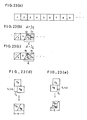
- FIG.23 schematically represents actual exemplary cases, wherein FIG.23(a) schematically shows a succession of segments each having a time-length of T time-units of original voice signals on which speech rate modification process is to be carried out, FIG.23(b) and FIG.23(c) schematically represent embodiments that the time-scale modification ratios ⁇ are 1/3 and 1/4, respectively.
- FIG.23(d) and FIG.23(e) schematically illustrate examples of individual detailed process of the mutual addition calculation.
- FIG.23(d) illustrates a case of addition calculation designated by D in FIG.23(b) and FIG.23(c), wherein the addition calculation under the condition that the correlation function takes a largest value when X B is displaced to the positive side by T c time-units with respect to X A .
- FIG. 23(e) illustrates another case of addition calculation, designated by E in FIG. 23(b) and FIG.23(c), wherein the addition calculation is done for the same condition when X B is displaced to the negative side by T c time-units with respect to X A .
- there are time intervals designated by E which correspond to the time interval E of FIG.23(e). In these time intervals, time sections extending outside the overlapping time interval may overlap also to adjacent time intervals and hence it is necessary to perform the amplitude adjustments also in those adjacent time intervals.
- signals X A and X B are multiplied respectively by window functions which are complementary to each other, one being a gradually increasing window function and the other being a gradually decreasing window function. And a signal obtained by adding these windowed signals is issued, and a signal X C subsequent to X B is issued, and these process is repeated.
- a speech voice having an ample naturalness with less discontinuities in signal amplitude can be issued for a range of the time-scale modification ratio of ⁇ ⁇ 0.5.
- FIG.24 schematically illustrates modified exemplary cases obtained by modifying the above-mentioned embodiment, wherein FIG.24(a) schematically shows a succession of segments each having a time-length of T time-units of an original voice signal on which the speech rate modification process is to be carried out, FIG.24(b) and FIG.24(c) schematically represent embodiments that the the time-scale modification ratios a are 1/3 and 1/4, respectively, and FIG.24(d) and FIG.24(e) schematically illustrate examples of detailed individual process of the addition calculation.
- FIG.24(d) illustrates a case of addition calculation designated by D in FIG.24(b) and FIG.24(c), wherein the addition calculation is done under a condition that the correlation function takes a largest value when X B is displaced to the positive side by T c time-units with respect to X A .
- FIG. 24(e) illustrates another case of addition calculation, designated by E in FIG.24(b) and FIG.24(c), wherein the addition calculation for the same condition is done when X B is displaced to the negative side by T c time-units with respect to X A and time sections extending outside the leading and rear edges of the overlapping time interval are discarded.
Landscapes
- Engineering & Computer Science (AREA)
- Computational Linguistics (AREA)
- Quality & Reliability (AREA)
- Signal Processing (AREA)
- Health & Medical Sciences (AREA)
- Audiology, Speech & Language Pathology (AREA)
- Human Computer Interaction (AREA)
- Physics & Mathematics (AREA)
- Acoustics & Sound (AREA)
- Multimedia (AREA)
- Compression, Expansion, Code Conversion, And Decoders (AREA)
- Signal Processing Not Specific To The Method Of Recording And Reproducing (AREA)
Applications Claiming Priority (6)
| Application Number | Priority Date | Filing Date | Title |
|---|---|---|---|
| JP1262391A JP2890530B2 (ja) | 1989-10-06 | 1989-10-06 | 音声速度変換装置 |
| JP262391/89 | 1989-10-06 | ||
| JP2013857A JP2669088B2 (ja) | 1990-01-24 | 1990-01-24 | 音声速度変換装置 |
| JP13857/90 | 1990-01-24 | ||
| JP223167/90 | 1990-08-23 | ||
| JP2223167A JP2532731B2 (ja) | 1990-08-23 | 1990-08-23 | 音声速度変換装置と音声速度変換方法 |
Publications (3)
| Publication Number | Publication Date |
|---|---|
| EP0427953A2 true EP0427953A2 (de) | 1991-05-22 |
| EP0427953A3 EP0427953A3 (en) | 1991-05-29 |
| EP0427953B1 EP0427953B1 (de) | 1996-01-17 |
Family
ID=27280430
Family Applications (1)
| Application Number | Title | Priority Date | Filing Date |
|---|---|---|---|
| EP90119083A Expired - Lifetime EP0427953B1 (de) | 1989-10-06 | 1990-10-04 | Einrichtung und Methode zur Veränderung von Sprechgeschwindigkeit |
Country Status (3)
| Country | Link |
|---|---|
| US (1) | US5341432A (de) |
| EP (1) | EP0427953B1 (de) |
| DE (1) | DE69024919T2 (de) |
Cited By (5)
| Publication number | Priority date | Publication date | Assignee | Title |
|---|---|---|---|---|
| EP0527527A3 (en) * | 1991-08-09 | 1993-05-05 | Koninkl Philips Electronics Nv | Method and apparatus for manipulating pitch and duration of a physical audio signal |
| EP0608833A3 (de) * | 1993-01-25 | 1995-01-25 | Matsushita Electric Industrial Co Ltd | Verfahren und Vorrichtung zur Durchführung einer Zeitskalenmodifikation von Sprachsignalen. |
| EP0865026A3 (de) * | 1997-03-14 | 1999-02-10 | GRUNDIG Aktiengesellschaft | Effizientes Verfahren zur Geschwindigkeitsmodifikation von Sprachsignalen |
| EP0910065B1 (de) * | 1997-03-14 | 2003-07-09 | Nippon Hoso Kyokai | Sprachschnellheitsveränderungsverfahren und vorrichtung |
| US8570328B2 (en) | 2000-12-12 | 2013-10-29 | Epl Holdings, Llc | Modifying temporal sequence presentation data based on a calculated cumulative rendition period |
Families Citing this family (57)
| Publication number | Priority date | Publication date | Assignee | Title |
|---|---|---|---|---|
| DE4227826C2 (de) * | 1991-08-23 | 1999-07-22 | Hitachi Ltd | Digitales Verarbeitungsgerät für akustische Signale |
| US5717818A (en) * | 1992-08-18 | 1998-02-10 | Hitachi, Ltd. | Audio signal storing apparatus having a function for converting speech speed |
| JP3088580B2 (ja) * | 1993-02-19 | 2000-09-18 | 松下電器産業株式会社 | 変換符号化装置のブロックサイズ決定法 |
| US5717823A (en) * | 1994-04-14 | 1998-02-10 | Lucent Technologies Inc. | Speech-rate modification for linear-prediction based analysis-by-synthesis speech coders |
| US5920842A (en) * | 1994-10-12 | 1999-07-06 | Pixel Instruments | Signal synchronization |
| JP3328080B2 (ja) * | 1994-11-22 | 2002-09-24 | 沖電気工業株式会社 | コード励振線形予測復号器 |
| JPH10511472A (ja) * | 1994-12-08 | 1998-11-04 | ザ リージェンツ オブ ザ ユニバーシティ オブ カリフォルニア | 言語障害者間の語音の認識を向上させるための方法および装置 |
| US5694521A (en) * | 1995-01-11 | 1997-12-02 | Rockwell International Corporation | Variable speed playback system |
| JP2976860B2 (ja) * | 1995-09-13 | 1999-11-10 | 松下電器産業株式会社 | 再生装置 |
| KR100251497B1 (ko) * | 1995-09-30 | 2000-06-01 | 윤종용 | 음성신호 변속재생방법 및 그 장치 |
| US5828994A (en) * | 1996-06-05 | 1998-10-27 | Interval Research Corporation | Non-uniform time scale modification of recorded audio |
| US6109107A (en) * | 1997-05-07 | 2000-08-29 | Scientific Learning Corporation | Method and apparatus for diagnosing and remediating language-based learning impairments |
| US5960387A (en) * | 1997-06-12 | 1999-09-28 | Motorola, Inc. | Method and apparatus for compressing and decompressing a voice message in a voice messaging system |
| DK0887958T3 (da) * | 1997-06-23 | 2003-05-05 | Liechti Ag | Fremgangsmåde til komprimering af optagelser af omgivelseslyd, fremgangsmåde til detektering af programelementer deri, indretninger og computerprogram dertil |
| US6159014A (en) * | 1997-12-17 | 2000-12-12 | Scientific Learning Corp. | Method and apparatus for training of cognitive and memory systems in humans |
| US6019607A (en) * | 1997-12-17 | 2000-02-01 | Jenkins; William M. | Method and apparatus for training of sensory and perceptual systems in LLI systems |
| US5927988A (en) * | 1997-12-17 | 1999-07-27 | Jenkins; William M. | Method and apparatus for training of sensory and perceptual systems in LLI subjects |
| US6249766B1 (en) * | 1998-03-10 | 2001-06-19 | Siemens Corporate Research, Inc. | Real-time down-sampling system for digital audio waveform data |
| US6292454B1 (en) * | 1998-10-08 | 2001-09-18 | Sony Corporation | Apparatus and method for implementing a variable-speed audio data playback system |
| US6496794B1 (en) * | 1999-11-22 | 2002-12-17 | Motorola, Inc. | Method and apparatus for seamless multi-rate speech coding |
| US6718309B1 (en) | 2000-07-26 | 2004-04-06 | Ssi Corporation | Continuously variable time scale modification of digital audio signals |
| CN1278549C (zh) * | 2001-10-18 | 2006-10-04 | 松下电器产业株式会社 | 声像再现装置和声像再现方法 |
| US7426470B2 (en) * | 2002-10-03 | 2008-09-16 | Ntt Docomo, Inc. | Energy-based nonuniform time-scale modification of audio signals |
| GB0228245D0 (en) * | 2002-12-04 | 2003-01-08 | Mitel Knowledge Corp | Apparatus and method for changing the playback rate of recorded speech |
| US7509255B2 (en) * | 2003-10-03 | 2009-03-24 | Victor Company Of Japan, Limited | Apparatuses for adaptively controlling processing of speech signal and adaptively communicating speech in accordance with conditions of transmitting apparatus side and radio wave and methods thereof |
| US20050175972A1 (en) * | 2004-01-13 | 2005-08-11 | Neuroscience Solutions Corporation | Method for enhancing memory and cognition in aging adults |
| US20050153267A1 (en) * | 2004-01-13 | 2005-07-14 | Neuroscience Solutions Corporation | Rewards method and apparatus for improved neurological training |
| US7830862B2 (en) * | 2005-01-07 | 2010-11-09 | At&T Intellectual Property Ii, L.P. | System and method for modifying speech playout to compensate for transmission delay jitter in a voice over internet protocol (VoIP) network |
| KR100868679B1 (ko) * | 2005-06-01 | 2008-11-13 | 삼성전자주식회사 | 무선 통신시스템에서 프리앰블 신호 송수신 장치 및 방법 |
| US8345890B2 (en) * | 2006-01-05 | 2013-01-01 | Audience, Inc. | System and method for utilizing inter-microphone level differences for speech enhancement |
| JP5096932B2 (ja) * | 2006-01-24 | 2012-12-12 | パナソニック株式会社 | 変換装置 |
| US8194880B2 (en) * | 2006-01-30 | 2012-06-05 | Audience, Inc. | System and method for utilizing omni-directional microphones for speech enhancement |
| US8744844B2 (en) * | 2007-07-06 | 2014-06-03 | Audience, Inc. | System and method for adaptive intelligent noise suppression |
| US9185487B2 (en) * | 2006-01-30 | 2015-11-10 | Audience, Inc. | System and method for providing noise suppression utilizing null processing noise subtraction |
| US8204252B1 (en) | 2006-10-10 | 2012-06-19 | Audience, Inc. | System and method for providing close microphone adaptive array processing |
| US8934641B2 (en) | 2006-05-25 | 2015-01-13 | Audience, Inc. | Systems and methods for reconstructing decomposed audio signals |
| US8150065B2 (en) * | 2006-05-25 | 2012-04-03 | Audience, Inc. | System and method for processing an audio signal |
| US8949120B1 (en) | 2006-05-25 | 2015-02-03 | Audience, Inc. | Adaptive noise cancelation |
| US8204253B1 (en) | 2008-06-30 | 2012-06-19 | Audience, Inc. | Self calibration of audio device |
| US8849231B1 (en) | 2007-08-08 | 2014-09-30 | Audience, Inc. | System and method for adaptive power control |
| US7817474B2 (en) * | 2006-06-01 | 2010-10-19 | Microchip Technology Incorporated | Method for programming and erasing an array of NMOS EEPROM cells that minimizes bit disturbances and voltage withstand requirements for the memory array and supporting circuits |
| TWI312500B (en) * | 2006-12-08 | 2009-07-21 | Micro Star Int Co Ltd | Method of varying speech speed |
| US8259926B1 (en) | 2007-02-23 | 2012-09-04 | Audience, Inc. | System and method for 2-channel and 3-channel acoustic echo cancellation |
| US8189766B1 (en) | 2007-07-26 | 2012-05-29 | Audience, Inc. | System and method for blind subband acoustic echo cancellation postfiltering |
| US8143620B1 (en) | 2007-12-21 | 2012-03-27 | Audience, Inc. | System and method for adaptive classification of audio sources |
| US8180064B1 (en) | 2007-12-21 | 2012-05-15 | Audience, Inc. | System and method for providing voice equalization |
| US8194882B2 (en) | 2008-02-29 | 2012-06-05 | Audience, Inc. | System and method for providing single microphone noise suppression fallback |
| US8355511B2 (en) | 2008-03-18 | 2013-01-15 | Audience, Inc. | System and method for envelope-based acoustic echo cancellation |
| US8521530B1 (en) | 2008-06-30 | 2013-08-27 | Audience, Inc. | System and method for enhancing a monaural audio signal |
| US8774423B1 (en) | 2008-06-30 | 2014-07-08 | Audience, Inc. | System and method for controlling adaptivity of signal modification using a phantom coefficient |
| EP2141696A1 (de) * | 2008-07-03 | 2010-01-06 | Deutsche Thomson OHG | Verfahren zur Zeitskalierung einer Folge aus Eingabesignalwerten |
| US9008329B1 (en) | 2010-01-26 | 2015-04-14 | Audience, Inc. | Noise reduction using multi-feature cluster tracker |
| CN103718240B (zh) * | 2011-09-09 | 2017-02-15 | 松下电器(美国)知识产权公司 | 编码装置、解码装置、编码方法和解码方法 |
| US9640194B1 (en) | 2012-10-04 | 2017-05-02 | Knowles Electronics, Llc | Noise suppression for speech processing based on machine-learning mask estimation |
| GB201309823D0 (en) * | 2013-06-01 | 2013-07-17 | Metroic Ltd | Current measurement |
| US9536540B2 (en) | 2013-07-19 | 2017-01-03 | Knowles Electronics, Llc | Speech signal separation and synthesis based on auditory scene analysis and speech modeling |
| US9799330B2 (en) | 2014-08-28 | 2017-10-24 | Knowles Electronics, Llc | Multi-sourced noise suppression |
Family Cites Families (8)
| Publication number | Priority date | Publication date | Assignee | Title |
|---|---|---|---|---|
| US3786195A (en) * | 1971-08-13 | 1974-01-15 | Dc Dt Liquidating Partnership | Variable delay line signal processor for sound reproduction |
| US4246617A (en) * | 1979-07-30 | 1981-01-20 | Massachusetts Institute Of Technology | Digital system for changing the rate of recorded speech |
| US4464784A (en) * | 1981-04-30 | 1984-08-07 | Eventide Clockworks, Inc. | Pitch changer with glitch minimizer |
| US4597318A (en) * | 1983-01-18 | 1986-07-01 | Matsushita Electric Industrial Co., Ltd. | Wave generating method and apparatus using same |
| CA1242279A (en) * | 1984-07-10 | 1988-09-20 | Tetsu Taguchi | Speech signal processor |
| KR900001591B1 (ko) * | 1985-04-02 | 1990-03-15 | 마쯔시다덴기산교 가부시기가이샤 | 음정복원장치 |
| IL84902A (en) * | 1987-12-21 | 1991-12-15 | D S P Group Israel Ltd | Digital autocorrelation system for detecting speech in noisy audio signal |
| US4984253A (en) * | 1988-06-03 | 1991-01-08 | Hughes Aircraft Company | Apparatus and method for processing simultaneous radio frequency signals |
-
1990
- 1990-10-04 EP EP90119083A patent/EP0427953B1/de not_active Expired - Lifetime
- 1990-10-04 DE DE69024919T patent/DE69024919T2/de not_active Expired - Lifetime
-
1992
- 1992-12-16 US US07/993,526 patent/US5341432A/en not_active Expired - Lifetime
Cited By (8)
| Publication number | Priority date | Publication date | Assignee | Title |
|---|---|---|---|---|
| EP0527527A3 (en) * | 1991-08-09 | 1993-05-05 | Koninkl Philips Electronics Nv | Method and apparatus for manipulating pitch and duration of a physical audio signal |
| EP0608833A3 (de) * | 1993-01-25 | 1995-01-25 | Matsushita Electric Industrial Co Ltd | Verfahren und Vorrichtung zur Durchführung einer Zeitskalenmodifikation von Sprachsignalen. |
| US5630013A (en) * | 1993-01-25 | 1997-05-13 | Matsushita Electric Industrial Co., Ltd. | Method of and apparatus for performing time-scale modification of speech signals |
| EP0865026A3 (de) * | 1997-03-14 | 1999-02-10 | GRUNDIG Aktiengesellschaft | Effizientes Verfahren zur Geschwindigkeitsmodifikation von Sprachsignalen |
| EP0910065B1 (de) * | 1997-03-14 | 2003-07-09 | Nippon Hoso Kyokai | Sprachschnellheitsveränderungsverfahren und vorrichtung |
| US8570328B2 (en) | 2000-12-12 | 2013-10-29 | Epl Holdings, Llc | Modifying temporal sequence presentation data based on a calculated cumulative rendition period |
| US8797329B2 (en) | 2000-12-12 | 2014-08-05 | Epl Holdings, Llc | Associating buffers with temporal sequence presentation data |
| US9035954B2 (en) | 2000-12-12 | 2015-05-19 | Virentem Ventures, Llc | Enhancing a rendering system to distinguish presentation time from data time |
Also Published As
| Publication number | Publication date |
|---|---|
| EP0427953A3 (en) | 1991-05-29 |
| EP0427953B1 (de) | 1996-01-17 |
| DE69024919T2 (de) | 1996-10-17 |
| US5341432A (en) | 1994-08-23 |
| DE69024919D1 (de) | 1996-02-29 |
Similar Documents
| Publication | Publication Date | Title |
|---|---|---|
| EP0427953A2 (de) | Einrichtung und Methode zur Veränderung von Sprechgeschwindigkeit | |
| EP0608833B1 (de) | Verfahren und Vorrichtung zur Durchführung einer Zeitskalenmodifikation von Sprachsignalen | |
| US6718309B1 (en) | Continuously variable time scale modification of digital audio signals | |
| US7173986B2 (en) | Nonlinear overlap method for time scaling | |
| US4389540A (en) | Adaptive linear prediction filters | |
| US20090047003A1 (en) | Playback apparatus and method | |
| KR100303913B1 (ko) | 음성처리방법, 음성처리장치 및 기록재생장치 | |
| EP1426926B1 (de) | Vorrichtung und Verfahren zum Ändern der Wiedergabegeschwindigkeit von gespeicherten Sprachsignalen | |
| JP3402748B2 (ja) | 音声信号のピッチ周期抽出装置 | |
| EP0439347A2 (de) | Schallfeldsteuerungsvorrichtung | |
| CN112420062B (zh) | 一种音频信号处理方法及设备 | |
| US7010491B1 (en) | Method and system for waveform compression and expansion with time axis | |
| US5522010A (en) | Pitch control apparatus for setting coefficients for cross-fading operation in accordance with intervals between write address and a number of read addresses in a sampling cycle | |
| JP3379348B2 (ja) | ピッチ変換器 | |
| JP3422716B2 (ja) | 話速変換方法および装置および話速変換プログラムを格納した記録媒体 | |
| JP2890530B2 (ja) | 音声速度変換装置 | |
| JP2532731B2 (ja) | 音声速度変換装置と音声速度変換方法 | |
| JPH0351126B2 (de) | ||
| JPH06222794A (ja) | 音声速度変換方法 | |
| US4520502A (en) | Speech synthesizer | |
| JP2669088B2 (ja) | 音声速度変換装置 | |
| JP2812379B2 (ja) | 音源装置 | |
| KR100359988B1 (ko) | 실시간 화속 변환 장치 | |
| JP3233948B2 (ja) | 音程制御装置 | |
| US20050027518A1 (en) | Multiple step adaptive method for time scaling |
Legal Events
| Date | Code | Title | Description |
|---|---|---|---|
| PUAI | Public reference made under article 153(3) epc to a published international application that has entered the european phase |
Free format text: ORIGINAL CODE: 0009012 |
|
| PUAL | Search report despatched |
Free format text: ORIGINAL CODE: 0009013 |
|
| 17P | Request for examination filed |
Effective date: 19901004 |
|
| AK | Designated contracting states |
Kind code of ref document: A2 Designated state(s): DE FR GB |
|
| AK | Designated contracting states |
Kind code of ref document: A3 Designated state(s): DE FR GB |
|
| 17Q | First examination report despatched |
Effective date: 19930607 |
|
| GRAA | (expected) grant |
Free format text: ORIGINAL CODE: 0009210 |
|
| AK | Designated contracting states |
Kind code of ref document: B1 Designated state(s): DE FR GB |
|
| REF | Corresponds to: |
Ref document number: 69024919 Country of ref document: DE Date of ref document: 19960229 |
|
| ET | Fr: translation filed | ||
| PLBE | No opposition filed within time limit |
Free format text: ORIGINAL CODE: 0009261 |
|
| STAA | Information on the status of an ep patent application or granted ep patent |
Free format text: STATUS: NO OPPOSITION FILED WITHIN TIME LIMIT |
|
| 26N | No opposition filed | ||
| REG | Reference to a national code |
Ref country code: GB Ref legal event code: IF02 |
|
| PGFP | Annual fee paid to national office [announced via postgrant information from national office to epo] |
Ref country code: GB Payment date: 20090930 Year of fee payment: 20 |
|
| PGFP | Annual fee paid to national office [announced via postgrant information from national office to epo] |
Ref country code: DE Payment date: 20091001 Year of fee payment: 20 |
|
| PGFP | Annual fee paid to national office [announced via postgrant information from national office to epo] |
Ref country code: FR Payment date: 20091029 Year of fee payment: 20 |
|
| REG | Reference to a national code |
Ref country code: GB Ref legal event code: PE20 Expiry date: 20101003 |
|
| PG25 | Lapsed in a contracting state [announced via postgrant information from national office to epo] |
Ref country code: GB Free format text: LAPSE BECAUSE OF EXPIRATION OF PROTECTION Effective date: 20101003 |
|
| PG25 | Lapsed in a contracting state [announced via postgrant information from national office to epo] |
Ref country code: DE Free format text: LAPSE BECAUSE OF EXPIRATION OF PROTECTION Effective date: 20101004 |