EP0439347A2 - Schallfeldsteuerungsvorrichtung - Google Patents
Schallfeldsteuerungsvorrichtung Download PDFInfo
- Publication number
- EP0439347A2 EP0439347A2 EP91300528A EP91300528A EP0439347A2 EP 0439347 A2 EP0439347 A2 EP 0439347A2 EP 91300528 A EP91300528 A EP 91300528A EP 91300528 A EP91300528 A EP 91300528A EP 0439347 A2 EP0439347 A2 EP 0439347A2
- Authority
- EP
- European Patent Office
- Prior art keywords
- sound field
- coefficient
- signal
- coefficients
- multipliers
- Prior art date
- Legal status (The legal status is an assumption and is not a legal conclusion. Google has not performed a legal analysis and makes no representation as to the accuracy of the status listed.)
- Withdrawn
Links
Images


Classifications
-
- G—PHYSICS
- G10—MUSICAL INSTRUMENTS; ACOUSTICS
- G10H—ELECTROPHONIC MUSICAL INSTRUMENTS; INSTRUMENTS IN WHICH THE TONES ARE GENERATED BY ELECTROMECHANICAL MEANS OR ELECTRONIC GENERATORS, OR IN WHICH THE TONES ARE SYNTHESISED FROM A DATA STORE
- G10H1/00—Details of electrophonic musical instruments
- G10H1/0091—Means for obtaining special acoustic effects
-
- G—PHYSICS
- G10—MUSICAL INSTRUMENTS; ACOUSTICS
- G10H—ELECTROPHONIC MUSICAL INSTRUMENTS; INSTRUMENTS IN WHICH THE TONES ARE GENERATED BY ELECTROMECHANICAL MEANS OR ELECTRONIC GENERATORS, OR IN WHICH THE TONES ARE SYNTHESISED FROM A DATA STORE
- G10H2210/00—Aspects or methods of musical processing having intrinsic musical character, i.e. involving musical theory or musical parameters or relying on musical knowledge, as applied in electrophonic musical tools or instruments
- G10H2210/155—Musical effects
- G10H2210/265—Acoustic effect simulation, i.e. volume, spatial, resonance or reverberation effects added to a musical sound, usually by appropriate filtering or delays
- G10H2210/295—Spatial effects, musical uses of multiple audio channels, e.g. stereo
- G10H2210/301—Soundscape or sound field simulation, reproduction or control for musical purposes, e.g. surround or 3D sound; Granular synthesis
-
- Y—GENERAL TAGGING OF NEW TECHNOLOGICAL DEVELOPMENTS; GENERAL TAGGING OF CROSS-SECTIONAL TECHNOLOGIES SPANNING OVER SEVERAL SECTIONS OF THE IPC; TECHNICAL SUBJECTS COVERED BY FORMER USPC CROSS-REFERENCE ART COLLECTIONS [XRACs] AND DIGESTS
- Y10—TECHNICAL SUBJECTS COVERED BY FORMER USPC
- Y10S—TECHNICAL SUBJECTS COVERED BY FORMER USPC CROSS-REFERENCE ART COLLECTIONS [XRACs] AND DIGESTS
- Y10S84/00—Music
- Y10S84/26—Reverberation
Definitions
- the present invention relates to a sound field control apparatus for producing a sound field which gives a listener with realistic feeling, and more particularly to a sound field control apparatus having a sound field switcher for changing one sound field to another.
- the sound field control apparatus produces a sound field which gives a listener with such a realistic feeling as if the listener were in the actual scene displayed on a screen. It has been a conventional practice, for eliminating the discontinuance of the output signal in switching the sound field from a certain sound field A to another sound field B to input the sound field signals of both fields in a sound field switcher, to multiply the sound field signal S A of the sound field A by a coefficient that starts from 1 and gradually decreases to ultimately 0 and the sound field signal S B of the sound field B by a coefficient that starts from 0 and gradually increases to ultimately 1 in the sound field switcher, and to output the sum of these multiplied signals.
- An object of the present invention is to provide a sound field control apparatus having a sound field switcher which has a single sound field signal input terminal and causes extremely reduced switching noise.
- a sound field control apparatus of the present invention comprises a sound field producer for processing a music signal to selectively produce one of plural sound field signals, plural delay circuits for sequentially delaying an output sound field signal of the sound field producer, plural multipliers for multiplying the output sound field signal of the sound field producer and the output signals of the plural delay circuits by specified coefficients, respectively, an adder for adding output signals of the plural multipliers, a coefficient changer for changing the coefficients of the plural multipliers, and a controller for controlling the sound field producer and the coefficient changer.
- the controller controls the sound field producer to switch the output sound field signal of the sound field producer from a first sound signal to a second sound field signal, and on the other hand controls the coefficient changer to change the coefficients of the plural multipliers so that the output signal of the adder is smoothly changed from the first sound field signal to the second sound field signal through a process in which the output signal of the adder contains gradually decreasing first sound field signal and gradually increasing second sound field signal.
- the coefficient changer may be comprised by a coefficient memory having stored therein plural sets of coefficients to be set to the plural multipliers in areas arranged in a specified sequence, and a coefficient counter for sequentially selecting the areas in the coefficient memory under control by the controller to change the coefficients of the multipliers.
- a sound field control apparatus comprises a sound field producer for selectively producing one of plural sound field signals, a sound field switching controller for instructing sound field switching of the sound field producer, plural delayers, plural multipliers, an adder, a cofficient memory having stored therein coefficients of the plural multipliers, and a coefficient counter for sequentially drawing out the coefficients from the coefficient memory by counting up or counting down under control by the sound field switching controller.
- a sound field signal S A of the sound field A is outputted, and the count value of the coefficient counter indicates 0 or a specified maximum count value N.
- coefficients containing only one coefficient of 1 and the remaining coefficients of 0 are stored. These coefficients are set to the respective multipliers.
- the sound field signal S A outputted from the sound field producer is delayed by the plural delayers connected in series, and the respective output signals of the sound field producer and the plural delayers are multiplied with the plural multipliers in which the abovementioned coefficients are set.
- a sum of outputs from all the multipliers obtained by the adder is outputted. Namely, from the sound field switcher either the sound field signal S A or the delayed one of the sound field signal S A is outputted.
- the coefficient counter increases the count value one by one from 0 to N or decreases the count value one by one from N to 0 in response to each sampling of the signal.
- the coefficients stored in the coefficient memory are read out according to the count value of the coefficient counter, and set to the respective multipliers.
- a sound field signal S B of the sound field B comes to be produced from the sound field producer.
- both the sound field signal S A and the sound field signal S B are subjected to delays, multiplications with the coefficients and addition to obtain an output signal which contains the sound field signals S A and S B mixed at a specified mixing ratio.
- the present invention there is no necessity to provide both of the sound field signals to be switched at all times during the sound field switching, so that sound field switching can be smoothly carried out. Accordingly, by using a sound field producer which cannot output plural sound field signals at a time and subjecting the output sound field signal from the sound field producer to an averaging processing, sound field switching can be carried out with a sound field switcher having a single input terminal without causing switching noise.
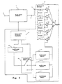
- Fig. 1 is a block diagram of a sound field control apparatus in one embodiment of the present invention.
- the sound field signals are digital signals.
- a sound field producer 1 for processing music signals to selectively produce any of plural sound fields is constituted by a music signal input terminal 2, a music signal processor 3 for processing a music signal based on a set sound field data, a sound field memory 4 having stored therein plural sound field data, a memory switch 5 for selecting a sound field data to be set to the music signal processor 3, and a sound field signal output terminal 6 for outputting the sound field signal produced in the sound field producer 1.
- the sound field data memory 4 has the data areas 41, 42, 43 and 44 which have stored therein data D A of a sound field A, data D B of a sound field B, data D C of a sound field C and data D D of a sound field D, respectively.
- the sound field switcher 13 comprises a sound field switching controller 7 for controlling the memory switch 5 and a coefficient counter 12, delayers 81 - 84 each for delaying its input signal by 1 sampling period, multipliers 91 - 95 for multiplying an input sound field signal to the sound field switcher 13 and output signals of the delayers 81 - 84 by specified coefficients respectively, an adder 10 for adding output signals of the multipliers 91 - 95, a coefficient memory 11 having stored therein coefficients to be set to the multipliers 91 - 95, a coefficient counter 12 for indicating a memory area of the coefficients to be read out from the coefficient memory 11 under control of the sound field switching controller 7, and a sound field signal input terminal 14 for inputting the sound field signal outputted from the sound field producer 1.
- Fig. 3 is a view showing the change by time of the input signals to the multipliers 91 - 95.
- n n ⁇ n
- n (time elapsed from start of sound field switching) / (sampling period) wherein n is an integer. Namely, the discrete time n becomes 0 at the time of the start of the sound field switching and increases by 1 with the lapse of 1 sampling period thereafter. Until the start of the sound field switching, n takes a negative value. Also, the values of the sound field signals S A , S B , S C and S D to be inputted to the sound field signal input terminal 14 in the discrete time n are expressed as S A (n), S B (n), S C (n) and S D (n), respectively.
- the data D A of the sound field A in the data area 41 of the sound field data memory 4 is selected by the memory switch 5 and set to the music signal processor 3.
- the music signal inputted to the music signal input terminal 2 is subjected to processing such as convolution by using the data D A with the music signal processor 3 to become the sound field signal S A and outputted from the sound field signal output terminal 6, which is inputted to the sound field signal input terminal 14.
- the sound field signal S A inputted to the sound field switcher 13 is delayed sequentially by the plural delayers 81 - 84 each by 1 sampling period. During the period until the start of the sound field switching, i.e., when n ⁇ 0, the input sound field signal S A and the delayed sound field signal S A from the delayers 81- 84, respectively, are inputted to the multipliers 91 - 95, as shown in Figs. 3, (a) and (b).
- the coefficient counter 12 continues to indicate 0, the coefficients 0, 0, 1, 0, 0 are read out from the area indicated by the count value 0 of the counter in the coefficient memory 11, and those coefficients are in a state of being set to the multipliers 91 - 95, respectively.
- the output signal from the sound field switcher 13 is a signal S A (n - 2) which is the inputted sound field signal S A delayed by the delayers 81 and 82.
- the count value of the coefficient counter 12 increases by 1 stepwise from 0 up to the specified maximum count value N in response to each sampling of the signal. In other words; from the start to the end of the sound field switching, the value of the discrete time n and the count value of the coefficient counter 12 are in agreement.
- the sound field signal S A continues to be inputted to the sound field signal input terminal 14, and the input sound field signal S A and the delayed sound field signal S A from the delayers 81 - 84, respectively, are inputted to the multipliers 91 - 95, as shown in Figs. 3, (b) and (c).
- the coefficients 0, 1/4, 1/2, 1/4, 0 are read out from the coefficient memory 11; when the count value is 2, the coefficients 0, 1/3, 1/3, 1/3, 0 are read out from the coefficient memory 11; when the count value is 3, the coefficients 1/8, 1/4, 1/4, 1/4, 1/8 are read out from the coefficient memory 11; and when the count value is between 4 and (N - 4), the coefficients 1/5, 1/5, 1/5, 1/5 are read out from the coefficient memory 11, and set to the multipliers 91 - 95 respectively as the coefficients thereof.
- the read out coefficients are respectively set to the multipliers 91 - 95 to be multiplied respectively with the input signals to the multipliers 91 - 95.
- the outputs of the multipliers 91 - 95 are added by the adder 10 to obtain an output sound field signal.
- the data D B of the sound field B in the data area 42 of the sound field data memory 4 is selected by the memory switch 5 and set to the music signal processor 3.
- the music signal inputted to the music signal input terminal 2 is provided with processings such as convolution processing with the music signal processor 3 based on the data D B to become a sound field signal S B and outputted from the sound field signal output terminal 6, which is inputted to the sound field signal input terminal 14. Thereafter, the sound field signal S B continues to be inputted until the next sound field switching is carried out.
- the input sound field signal S B and the delayed sound field signals S A from the delayers 81 - 84 are inputted to the multipliers 91 - 95, as shown in Fig. 3 (d).
- the input sound field signal S B and the sound field signals S B delayed respectively by the delayers 81 - 84 are inputted to the multipliers 91 - 95, as shown in Fig. 3 (h) .
- the input sound field signals S B and the sound field signals S B delayed respectively by the delayers 81 - 84 are inputted to the multipliers 91 - 95, as shown in Fig. 3 (i).
- the coefficients 0, 0, 1, 0, 0 are read out from the coefficient memory 11, at which time the output signals from the sound field switcher 13 are the signal S B (n - 2) which is the input sound field signal S B delayed by the delayers 81, 82. By this, the sound field switching from the sound field A to the sound field B is completed.
- the sound field signal S B is inputted to the sound field switcher 13, the coefficient counter 12 takes a count value of N, and the output signal from the sound field switcher 13 is the signal S B (n - 2) which is the input sound field signal S B delayed by the delayers 81, 82.
- the count value of the coefficient counter 12 decreases one by one on each sampling of the signals from N to 0, by the control of the sound signal switching controller 7.
- the count value of the coefficient counter 12 is (N/2), or comes to be closest to (N/2)
- the control of the sound field switching controller 7 the data D C of the sound field C in the data area 43 of the sound field data memory 4 is selected by the memory switch 5 and set to the music signal processor 3.
- the music signal inputted to the music signal input terminal 2 is subjected to processing such as convolution processing based on the data D C by the music signal processor 3 to become a sound field signal S C .
- the sound field signal S C is outputted from the sound field signal output terminal 6, and inputted to the sound field signal input terminal 14.
- the discrete time n is based on the 0 value of the starting time for the sound field switching from the sound field B to the sound field C.
- the delays, multiplications and addition of the sound field signals are carried out in the same manner as that when switching is made from the sound field A to the sound field B. Consequently, the switching from the sound field B to the sound field C is carried out by a single sound field signal input terminal and smoothly. Subsequently, sound field switching is similarly carried out from the sound field C to the sound field D.
- the count value of the coefficient counter 12 is 0 before the sound field switching, the count value is counted up one by one from the start of the sound field switching to the end thereof, and when the count value of the coefficient counter 12 is N before the sound field switching, the count value is counted down one by one from the start of the sound field switching to the end thereof. Under the condition where no sound field switching is carried out, the count value of the coefficient counter 12 is fixed to 0 or N.
- C j (0) is a coefficient of the multiplier 91 in case of the counter value j
- C j (1) is a coefficient of the multiplier 92 in case of the counter value j
- C j (2) is a coefficient of the multiplier 93 in case of the counter value j
- C j (3) is a coefficient of the multiplier 94 in case of the counter value j
- C j (4) is a coefficient of the multiplier 95 in case of the counter value j.
- the delay time to be delayed by one delayer normally to be equal to the sampling period of the music signal, e.g. (1/44.1) msec., and the time required for signal switching to be about 25 msec.
- signal switching can be carried out with the sound field switcher having a single sound field signal input terminal, and without generating a large switching noise.
- the coefficients stored in the coefficient memory 11 may be set such that, when the counter value is near 0, greater weights are given to the coefficients of the multipliers closer to the center multiplier, and as the counter value comes close to (N/2), the coefficients are gradually averaged, and that the coefficients for the counter values from (N/2) to N are set to be symmetrical with the coefficients for the counter values from 0 to (N/2).
- the values of the coefficients to be stored in the coefficient memory 11 are not limited to the values shown in this embodiment.
- the coefficient memory 11 may be a memory for the counter values between 0 to (N/2), and the coefficient counter 12 starts from 0 and increases one by one up to (N/2), turns back at (N/2), and decreases one by one down to 0, thereby carrying out a sound field switching equivalent to this embodiment.
- Specifications for setting the coefficient memory 11 and the coefficient counter 12 are not limited to those shown in this embodiment.
- Fig. 2 is a block diagram of a sound field control apparatus according to another embodiment of the present invention.
- the sound field producer 1, music signal input terminal 2, delayers 81 - 84, multipliers 91 - 95, adder 10 and coefficient counter 12 are respectively the same as those of the embodiment in Fig. 1.
- the sound field switching controller 7 controls the sound field producer 1, coefficient counter 12 and coefficient memory switch 15.
- a music signal is inputted from the music signal input terminal 2, and the inputted music signal is processed into a sound field signal S A by the sound field producer 1 under the control of the sound field switching controller 7.
- the sound field signal S A is inputted to the sound field switcher 13 through the sound field signal input terminal 14.
- the inputted sound field signal S A and the sound field signals S A delayed by the delayers 81 - 84 are respectively multiplied by the multipliers 91 - 95.
- the results of multiplication are all added by the adder 10 to obtain an output sound field signal.
- the coefficients of the multipliers 91 - 95 only one is a coefficient of 1, and all the rest are the coefficients of 0.
- the output from the sound field switcher 13 either the sound field signal S A or the slightly delayed sound field signal S A is outputted.
- the coefficient memory switch 15 selects, under the control of the sound field switching controller 7, the coefficient memory 11a which has stored therein coefficients most suited to the sound field switching from the sound field A to the sound field B out of the coefficient memories 11a - 11c.
- the coefficient memory 11a which has stored therein coefficients most suited to the sound field switching from the sound field A to the sound field B out of the coefficient memories 11a - 11c.
- the coefficient memory 11a having stored therein coefficients in which a larger weight is given to the coefficients of the multipliers positioned close to the center one of the rows of multipliers.
- the coefficient counter 12 increases the count value one by one from 0 to N by each sampling cycle of the sound field signal.
- the coefficients stored in an area of the memory 11a indicated by each count value of the coefficient counter 12 are set to the multipliers 91 - 95.
- a sound field signal S B is produced by the sound field producer 1.
- the sound field signal S B is inputted to the sound field switcher 13 from the sound field signal input terminal 14.
- coefficients are so set that only one is the coefficient of 1 and all the rest are the coefficients of 0,
- the output from the sound field switcher 13 either the sound field signal S B or the slightly delayed sound field signal S B is outputted. In this manner, sound field switching from the sound field A to the sound field B is completed.
- the coefficient memory switch 15 selects, under the control of the sound field switching controller 7, the coefficient memory 11b which has stored therein coefficients most suited to the sound field switching from the sound field B to the sound field C out of the coefficient memories 11a - 11c to carry out the sound field switching in the same manner as in the case of the switching from the sound field A to the sound field B.
- the coefficient memory 11c is selected in case of switching from ther sound field C to the sound field D.
- the delay time to be delayed by one delayer normally to be equal to the sampling period of the music signal, e.g. (1/44.1) msec., and the time required for signal switching to be about 25 msec.
- signal switching can be carried out with the sound field switcher having a single sound field signal input terminal, and without generating a large switching noise. Further, by selecting one of the plural coefficient memories, multiplications and addition can be carried out by using coefficients which are most suited to the sound field switching at that time, so that the switching noise can be further reduced.
- the coefficients stored in each of the coefficient memories 11a - 11c may be set such that, when the counter value is near 0, greater weights are given to the coefficients of the multipliers located closer to the center multiplier, and as the counter value comes close to (N/2), the coefficients are gradually averaged, and that the coefficients for the counter values from (N/2) to N are set symmetrical with the coefficients for the counter values from 0 to (N/2).
- each of the coefficient memories 11a - 11c may be a memory for the counter coefficien of from. 0 to (N/2), and the coefficient counter 12 starts from 0 and increases one by one up to (N/2), turns back at (N/2), and decreases one by one down to 0, thereby carrying out sound field switching equivalent to this embodiment.
Landscapes
- Physics & Mathematics (AREA)
- Engineering & Computer Science (AREA)
- Acoustics & Sound (AREA)
- Multimedia (AREA)
- Stereophonic System (AREA)
- Reverberation, Karaoke And Other Acoustics (AREA)
- Electrophonic Musical Instruments (AREA)
Applications Claiming Priority (2)
| Application Number | Priority Date | Filing Date | Title |
|---|---|---|---|
| JP2017343A JPH03220912A (ja) | 1990-01-26 | 1990-01-26 | 信号切り換え装置 |
| JP17343/90 | 1990-01-26 |
Publications (2)
| Publication Number | Publication Date |
|---|---|
| EP0439347A2 true EP0439347A2 (de) | 1991-07-31 |
| EP0439347A3 EP0439347A3 (en) | 1992-04-15 |
Family
ID=11941410
Family Applications (1)
| Application Number | Title | Priority Date | Filing Date |
|---|---|---|---|
| EP19910300528 Withdrawn EP0439347A3 (en) | 1990-01-26 | 1991-01-24 | Sound field control apparatus |
Country Status (3)
| Country | Link |
|---|---|
| US (1) | US5073942A (de) |
| EP (1) | EP0439347A3 (de) |
| JP (1) | JPH03220912A (de) |
Families Citing this family (13)
| Publication number | Priority date | Publication date | Assignee | Title |
|---|---|---|---|---|
| US5342990A (en) | 1990-01-05 | 1994-08-30 | E-Mu Systems, Inc. | Digital sampling instrument employing cache-memory |
| US5386082A (en) * | 1990-05-08 | 1995-01-31 | Yamaha Corporation | Method of detecting localization of acoustic image and acoustic image localizing system |
| JP2898134B2 (ja) * | 1991-10-25 | 1999-05-31 | 株式会社河合楽器製作所 | ステレオ方式 |
| US5463691A (en) * | 1992-10-11 | 1995-10-31 | Casio Computer Co., Ltd. | Effect imparting apparatus having storage units for storing programs corresponding to form and effect to be imparted to an input signal and for storing output form programs to determine form of output signal with imparted effect |
| JP3293240B2 (ja) * | 1993-05-18 | 2002-06-17 | ヤマハ株式会社 | ディジタル信号処理装置 |
| US5617478A (en) * | 1994-04-11 | 1997-04-01 | Matsushita Electric Industrial Co., Ltd. | Sound reproduction system and a sound reproduction method |
| US5943427A (en) * | 1995-04-21 | 1999-08-24 | Creative Technology Ltd. | Method and apparatus for three dimensional audio spatialization |
| US6031916A (en) * | 1996-02-28 | 2000-02-29 | Kabushiki Kaisha Kawai Gakki Seisakusho | Sound effect adding device using DSP |
| JP2956642B2 (ja) * | 1996-06-17 | 1999-10-04 | ヤマハ株式会社 | 音場制御ユニットおよび音場制御装置 |
| US6188769B1 (en) * | 1998-11-13 | 2001-02-13 | Creative Technology Ltd. | Environmental reverberation processor |
| KR100539574B1 (ko) * | 2002-12-26 | 2005-12-29 | 엘지전자 주식회사 | 반향을 이용한 오디오 및 음성의 음색 변환 장치 및 방법 |
| US7107401B1 (en) | 2003-12-19 | 2006-09-12 | Creative Technology Ltd | Method and circuit to combine cache and delay line memory |
| JP6481905B2 (ja) * | 2017-03-15 | 2019-03-13 | カシオ計算機株式会社 | フィルタ特性変更装置、フィルタ特性変更方法、プログラムおよび電子楽器 |
Family Cites Families (13)
| Publication number | Priority date | Publication date | Assignee | Title |
|---|---|---|---|---|
| JPS5340886B2 (de) * | 1974-12-07 | 1978-10-30 | ||
| US4338581A (en) * | 1980-05-05 | 1982-07-06 | The Regents Of The University Of California | Room acoustics simulator |
| JPS583639A (ja) * | 1981-06-27 | 1983-01-10 | Nec Corp | フツ素処理剤 |
| GB8403509D0 (en) * | 1984-02-10 | 1984-03-14 | Barnett P W | Acoustic systems |
| JPS60256198A (ja) * | 1984-06-01 | 1985-12-17 | ヤマハ株式会社 | 効果付与装置 |
| US4731848A (en) * | 1984-10-22 | 1988-03-15 | Northwestern University | Spatial reverberator |
| US4706537A (en) * | 1985-03-07 | 1987-11-17 | Nippon Gakki Seizo Kabushiki Kaisha | Tone signal generation device |
| JPS61257099A (ja) * | 1985-05-10 | 1986-11-14 | Nippon Gakki Seizo Kk | 音響制御装置 |
| JP2666058B2 (ja) * | 1985-05-15 | 1997-10-22 | ヤマハ株式会社 | 収音再生制御装置 |
| EP0229926B1 (de) * | 1985-11-29 | 1993-11-18 | Yamaha Corporation | Tonsignalsbehandlungsvorrichtung |
| JPS62173900A (ja) * | 1986-01-28 | 1987-07-30 | Toshiba Corp | デジタルオ−デイオ信号再生装置 |
| JPH07118840B2 (ja) * | 1986-09-30 | 1995-12-18 | ヤマハ株式会社 | 再生特性制御回路 |
| US4937875A (en) * | 1989-03-28 | 1990-06-26 | Pioneer Electronic Corporation | Audio signal processing apparatus |
-
1990
- 1990-01-26 JP JP2017343A patent/JPH03220912A/ja active Pending
-
1991
- 1991-01-24 US US07/645,476 patent/US5073942A/en not_active Expired - Fee Related
- 1991-01-24 EP EP19910300528 patent/EP0439347A3/en not_active Withdrawn
Also Published As
| Publication number | Publication date |
|---|---|
| JPH03220912A (ja) | 1991-09-30 |
| EP0439347A3 (en) | 1992-04-15 |
| US5073942A (en) | 1991-12-17 |
Similar Documents
| Publication | Publication Date | Title |
|---|---|---|
| EP0427953B1 (de) | Einrichtung und Methode zur Veränderung von Sprechgeschwindigkeit | |
| EP0439347A2 (de) | Schallfeldsteuerungsvorrichtung | |
| US6279021B1 (en) | Digital filters | |
| US5210806A (en) | Digital audio signal processing apparatus | |
| US5287299A (en) | Method and apparatus for implementing a digital filter employing coefficients expressed as sums of 2 to an integer power | |
| US6360240B2 (en) | Digital filters | |
| US4803731A (en) | Reverbation imparting device | |
| US8995684B2 (en) | Apparatus and method for post-processing and outputting digital audio data in real time | |
| EP0734018A2 (de) | Gerät zur Audiodatenverarbeitung | |
| US5048088A (en) | Linear predictive speech analysis-synthesis apparatus | |
| EP0178933B1 (de) | Autokorrelationsfilter | |
| JPH0225987A (ja) | 画像処理集積回路装置 | |
| US5418321A (en) | Audio channel system for providing an analog signal corresponding to a sound waveform in a computer system | |
| EP0405915B1 (de) | Datenverarbeitungssystem für Audiosignale | |
| JPH07177388A (ja) | ゴースト消去回路 | |
| JPH09284094A (ja) | デジタルフィルタバンク装置およびその作動方法 | |
| JP2003264451A (ja) | デジタルフィルタ | |
| EP0446917B1 (de) | Anzapfverstärkungsregulierungsschaltung mit hoher Geschwindigkeit in einem adaptiven Filter | |
| US5005149A (en) | Digital computation integrated circuit for convolution type computations | |
| US5255323A (en) | Digital signal processing device and audio apparatus using the same | |
| US5812677A (en) | Acoustic signal processing method and apparatus | |
| EP0117357A2 (de) | Schaltungsanordnung zur Zusammensetzung eines digitalen Signals | |
| JPH06318092A (ja) | 可変遅延回路 | |
| GB2296144A (en) | IIR type digital filter | |
| JPH1131945A (ja) | 非対称周波数応答特性を有する有限インパルス応答フィルタ |
Legal Events
| Date | Code | Title | Description |
|---|---|---|---|
| PUAI | Public reference made under article 153(3) epc to a published international application that has entered the european phase |
Free format text: ORIGINAL CODE: 0009012 |
|
| AK | Designated contracting states |
Kind code of ref document: A2 Designated state(s): DE FR GB NL |
|
| PUAL | Search report despatched |
Free format text: ORIGINAL CODE: 0009013 |
|
| AK | Designated contracting states |
Kind code of ref document: A3 Designated state(s): DE FR GB NL |
|
| STAA | Information on the status of an ep patent application or granted ep patent |
Free format text: STATUS: THE APPLICATION IS DEEMED TO BE WITHDRAWN |
|
| 18D | Application deemed to be withdrawn |
Effective date: 19921016 |