EP0428265B2 - Procédé et structure pour la réalisation de réactions catalytiques dans des structures de distillation - Google Patents
Procédé et structure pour la réalisation de réactions catalytiques dans des structures de distillation Download PDFInfo
- Publication number
- EP0428265B2 EP0428265B2 EP90311157A EP90311157A EP0428265B2 EP 0428265 B2 EP0428265 B2 EP 0428265B2 EP 90311157 A EP90311157 A EP 90311157A EP 90311157 A EP90311157 A EP 90311157A EP 0428265 B2 EP0428265 B2 EP 0428265B2
- Authority
- EP
- European Patent Office
- Prior art keywords
- plates
- liquid
- pair
- present
- pairs
- Prior art date
- Legal status (The legal status is an assumption and is not a legal conclusion. Google has not performed a legal analysis and makes no representation as to the accuracy of the status listed.)
- Expired - Lifetime
Links
Images

Classifications
-
- B—PERFORMING OPERATIONS; TRANSPORTING
- B01—PHYSICAL OR CHEMICAL PROCESSES OR APPARATUS IN GENERAL
- B01J—CHEMICAL OR PHYSICAL PROCESSES, e.g. CATALYSIS OR COLLOID CHEMISTRY; THEIR RELEVANT APPARATUS
- B01J16/00—Chemical processes in general for reacting liquids with non- particulate solids, e.g. sheet material; Apparatus specially adapted therefor
- B01J16/005—Chemical processes in general for reacting liquids with non- particulate solids, e.g. sheet material; Apparatus specially adapted therefor in the presence of catalytically active bodies, e.g. porous plates
-
- B—PERFORMING OPERATIONS; TRANSPORTING
- B01—PHYSICAL OR CHEMICAL PROCESSES OR APPARATUS IN GENERAL
- B01D—SEPARATION
- B01D3/00—Distillation or related exchange processes in which liquids are contacted with gaseous media, e.g. stripping
- B01D3/009—Distillation or related exchange processes in which liquids are contacted with gaseous media, e.g. stripping in combination with chemical reactions
-
- B—PERFORMING OPERATIONS; TRANSPORTING
- B01—PHYSICAL OR CHEMICAL PROCESSES OR APPARATUS IN GENERAL
- B01J—CHEMICAL OR PHYSICAL PROCESSES, e.g. CATALYSIS OR COLLOID CHEMISTRY; THEIR RELEVANT APPARATUS
- B01J15/00—Chemical processes in general for reacting gaseous media with non-particulate solids, e.g. sheet material; Apparatus specially adapted therefor
- B01J15/005—Chemical processes in general for reacting gaseous media with non-particulate solids, e.g. sheet material; Apparatus specially adapted therefor in the presence of catalytically active bodies, e.g. porous plates
-
- B—PERFORMING OPERATIONS; TRANSPORTING
- B01—PHYSICAL OR CHEMICAL PROCESSES OR APPARATUS IN GENERAL
- B01J—CHEMICAL OR PHYSICAL PROCESSES, e.g. CATALYSIS OR COLLOID CHEMISTRY; THEIR RELEVANT APPARATUS
- B01J19/00—Chemical, physical or physico-chemical processes in general; Their relevant apparatus
- B01J19/32—Packing elements in the form of grids or built-up elements for forming a unit or module inside the apparatus for mass or heat transfer
-
- B—PERFORMING OPERATIONS; TRANSPORTING
- B01—PHYSICAL OR CHEMICAL PROCESSES OR APPARATUS IN GENERAL
- B01J—CHEMICAL OR PHYSICAL PROCESSES, e.g. CATALYSIS OR COLLOID CHEMISTRY; THEIR RELEVANT APPARATUS
- B01J35/00—Catalysts, in general, characterised by their form or physical properties
- B01J35/50—Catalysts, in general, characterised by their form or physical properties characterised by their shape or configuration
- B01J35/56—Foraminous structures having flow-through passages or channels, e.g. grids or three-dimensional [3D] monoliths
-
- B—PERFORMING OPERATIONS; TRANSPORTING
- B01—PHYSICAL OR CHEMICAL PROCESSES OR APPARATUS IN GENERAL
- B01J—CHEMICAL OR PHYSICAL PROCESSES, e.g. CATALYSIS OR COLLOID CHEMISTRY; THEIR RELEVANT APPARATUS
- B01J2219/00—Chemical, physical or physico-chemical processes in general; Their relevant apparatus
- B01J2219/32—Details relating to packing elements in the form of grids or built-up elements for forming a unit of module inside the apparatus for mass or heat transfer
- B01J2219/322—Basic shape of the elements
- B01J2219/32203—Sheets
- B01J2219/32206—Flat sheets
-
- B—PERFORMING OPERATIONS; TRANSPORTING
- B01—PHYSICAL OR CHEMICAL PROCESSES OR APPARATUS IN GENERAL
- B01J—CHEMICAL OR PHYSICAL PROCESSES, e.g. CATALYSIS OR COLLOID CHEMISTRY; THEIR RELEVANT APPARATUS
- B01J2219/00—Chemical, physical or physico-chemical processes in general; Their relevant apparatus
- B01J2219/32—Details relating to packing elements in the form of grids or built-up elements for forming a unit of module inside the apparatus for mass or heat transfer
- B01J2219/322—Basic shape of the elements
- B01J2219/32203—Sheets
- B01J2219/3221—Corrugated sheets
-
- B—PERFORMING OPERATIONS; TRANSPORTING
- B01—PHYSICAL OR CHEMICAL PROCESSES OR APPARATUS IN GENERAL
- B01J—CHEMICAL OR PHYSICAL PROCESSES, e.g. CATALYSIS OR COLLOID CHEMISTRY; THEIR RELEVANT APPARATUS
- B01J2219/00—Chemical, physical or physico-chemical processes in general; Their relevant apparatus
- B01J2219/32—Details relating to packing elements in the form of grids or built-up elements for forming a unit of module inside the apparatus for mass or heat transfer
- B01J2219/322—Basic shape of the elements
- B01J2219/32203—Sheets
- B01J2219/32213—Plurality of essentially parallel sheets
-
- B—PERFORMING OPERATIONS; TRANSPORTING
- B01—PHYSICAL OR CHEMICAL PROCESSES OR APPARATUS IN GENERAL
- B01J—CHEMICAL OR PHYSICAL PROCESSES, e.g. CATALYSIS OR COLLOID CHEMISTRY; THEIR RELEVANT APPARATUS
- B01J2219/00—Chemical, physical or physico-chemical processes in general; Their relevant apparatus
- B01J2219/32—Details relating to packing elements in the form of grids or built-up elements for forming a unit of module inside the apparatus for mass or heat transfer
- B01J2219/322—Basic shape of the elements
- B01J2219/32203—Sheets
- B01J2219/32224—Sheets characterised by the orientation of the sheet
- B01J2219/32227—Vertical orientation
-
- B—PERFORMING OPERATIONS; TRANSPORTING
- B01—PHYSICAL OR CHEMICAL PROCESSES OR APPARATUS IN GENERAL
- B01J—CHEMICAL OR PHYSICAL PROCESSES, e.g. CATALYSIS OR COLLOID CHEMISTRY; THEIR RELEVANT APPARATUS
- B01J2219/00—Chemical, physical or physico-chemical processes in general; Their relevant apparatus
- B01J2219/32—Details relating to packing elements in the form of grids or built-up elements for forming a unit of module inside the apparatus for mass or heat transfer
- B01J2219/322—Basic shape of the elements
- B01J2219/32203—Sheets
- B01J2219/32237—Sheets comprising apertures or perforations
-
- B—PERFORMING OPERATIONS; TRANSPORTING
- B01—PHYSICAL OR CHEMICAL PROCESSES OR APPARATUS IN GENERAL
- B01J—CHEMICAL OR PHYSICAL PROCESSES, e.g. CATALYSIS OR COLLOID CHEMISTRY; THEIR RELEVANT APPARATUS
- B01J2219/00—Chemical, physical or physico-chemical processes in general; Their relevant apparatus
- B01J2219/32—Details relating to packing elements in the form of grids or built-up elements for forming a unit of module inside the apparatus for mass or heat transfer
- B01J2219/322—Basic shape of the elements
- B01J2219/32203—Sheets
- B01J2219/32248—Sheets comprising areas that are raised or sunken from the plane of the sheet
-
- B—PERFORMING OPERATIONS; TRANSPORTING
- B01—PHYSICAL OR CHEMICAL PROCESSES OR APPARATUS IN GENERAL
- B01J—CHEMICAL OR PHYSICAL PROCESSES, e.g. CATALYSIS OR COLLOID CHEMISTRY; THEIR RELEVANT APPARATUS
- B01J2219/00—Chemical, physical or physico-chemical processes in general; Their relevant apparatus
- B01J2219/32—Details relating to packing elements in the form of grids or built-up elements for forming a unit of module inside the apparatus for mass or heat transfer
- B01J2219/322—Basic shape of the elements
- B01J2219/32203—Sheets
- B01J2219/32255—Other details of the sheets
-
- B—PERFORMING OPERATIONS; TRANSPORTING
- B01—PHYSICAL OR CHEMICAL PROCESSES OR APPARATUS IN GENERAL
- B01J—CHEMICAL OR PHYSICAL PROCESSES, e.g. CATALYSIS OR COLLOID CHEMISTRY; THEIR RELEVANT APPARATUS
- B01J2219/00—Chemical, physical or physico-chemical processes in general; Their relevant apparatus
- B01J2219/32—Details relating to packing elements in the form of grids or built-up elements for forming a unit of module inside the apparatus for mass or heat transfer
- B01J2219/324—Composition or microstructure of the elements
- B01J2219/32466—Composition or microstructure of the elements comprising catalytically active material
-
- Y—GENERAL TAGGING OF NEW TECHNOLOGICAL DEVELOPMENTS; GENERAL TAGGING OF CROSS-SECTIONAL TECHNOLOGIES SPANNING OVER SEVERAL SECTIONS OF THE IPC; TECHNICAL SUBJECTS COVERED BY FORMER USPC CROSS-REFERENCE ART COLLECTIONS [XRACs] AND DIGESTS
- Y10—TECHNICAL SUBJECTS COVERED BY FORMER USPC
- Y10S—TECHNICAL SUBJECTS COVERED BY FORMER USPC CROSS-REFERENCE ART COLLECTIONS [XRACs] AND DIGESTS
- Y10S203/00—Distillation: processes, separatory
- Y10S203/06—Reactor-distillation
Definitions
- This invention relates in general to a mass transfer or distillation column and, more particularly, to a structure within the column for concurrently contacting a fluid stream with a particulate solid catalyst while distilling the reaction product.
- the use of a catalyst packed distillation column allows concurrent catalytic reaction of a fluid stream flowing through the catalyst and fractionation of the resulting reaction product.
- the use of solid, particulate catalysts in a conventional fixed bed within such columns generally results in high pressure drop within the column as the low permeability of the catalyst bed impedes the upward flowing vapor and downward flowing liquid. Compaction and breakage of the catalyst in conventional fixed beds inevitably occurs and may further increase the pressure drop or may result in preferential channeling of the fluid streams through areas of high permeability. Portions of the catalyst bed having low permeability are then segregated from the fluid streams and the efficiency of the reaction process is reduced.
- the particulate catalyst in some columns has been placed into a plurality of pockets within a cloth belt.
- the belt is then supported by a specially designed support structure such as an open knitted stainless steel wire joined with the cloth belt.
- US-A-4,242,530 provides an example of one such structure. While these types of reaction with distillation structures may provide reduced pressure drop and reduced channelling within the distillation column, they often fail to achieve the distillation performances obtainable with many types of structured packings.
- both the catalyst containers and support structure must be dismounted and replaced when the catalyst is spent. This can be a frequent occurrence when catalysts which have a cycle life as short as several months are used and results in significant losses in operating time.
- Structured packings are also well known in the art including packings made of sheet material and having configurations for promoting vapour liquid contact.
- a particularly advantageous structured packing is that shown in US-A-4,296,050. It has not heretofore been known to combine a structured packing of the type shown in US-A-4,296,050 with a fixed catalyst bed in a column where distillation and reaction occur simultaneously.
- US-A-4439350 discloses a structure for providing concurrent catalytic reaction with distillation of fluid streams, the structure comprising a plurality of vertically extending, liquid and vapour permeable plates disposed in facing pairs and presenting a plurality of open areas between the plates of each pair; a particulate catalyst bed substantially filling at least some of the open areas; and means for retaining the catalyst in the open areas; and the present invention is characterised over this either by each adjacent pair of plates being in contact with at least one adjoining pair to present a plurality of contiguous pairs of plates, at least one of the contacting plates of contiguous pairs being corrugated whereby the contiguous pairs present therebetween flow channels for descending liquid and ascending vapour streams or by each adjacent pair of plates being in contact with at least one adjoining pair to present a plurality of contiguous pairs of plates, the contacting plates of contiguous pairs having spaced apart convex sections by which the contacting plates contact one another whereby the contiguous pairs present therebetween flow channels for descending liquid and ascend
- EP-A-0396650 discloses a mass transfer column being equipped with a structure for catalytic distillation processes and the structure, which comprises inter alia a plurality of plates (52), pairs (52a, 52b) of said plates forming areas between them which are filled with catalytic material, said catalytic material being retained in said areas by appropriate means (the edges of the plates being tightly connected with each other to form pockets), each adjacent pair of plates being in contact with an adjoining pair (cf.
- Said plates (52a, 52b) are permeable for the reactants which are present in liquid and vaporous form (cf. claims 1, 14).
- Said plates are of corrugated form and held in spaced apart relationship to present the areas (pockets for retaining the catalyst bed), the areas between said plates comprising a plurality of intersecting planar areas parallel to the planes of the corrugations (cf. fig 5).
- the catalyst bed comprises inter alia particulate catalyst material (cf. claim 17).
- the corresponding process for concurrent catalytic reaction with distillation of fluid streams within a mass transfer column, comprises the steps of providing a plurality of pairs of vertically extending, liquid and vapour permeable plates which present mass transfer zones for liquid-vapour interaction and which have between the plates of each pair open areas for receiving a particulate catalyst; providing a catalyst bed in the open areas to form a catalytic reaction zone; feeding a liquid stream to the column; directing the liquid stream through the catalytic reaction zone to react catalytically the liquid stream; concurrently distilling a portion of the liquid stream in the column to present a vapour stream directing the vapour stream and liquid stream to the mass transfer zones for interaction; and withdrawing fluid distillation products and the reaction product from the zones characterised either by each adjacent pair of plates being in contact with at least one adjoining pair to present a plurality of contiguous pairs of plates, at least one of the contacting plates of contiguous pairs being corrugated whereby the contiguous pairs present therebetween flow channels for descending liquid and ascending vapour streams or
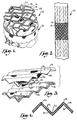
- Structure 10 is shaped for placement within a cylindrical mass transfer column 12 to allow concurrent catalytic reaction of fluid streams and distillation of the reaction products. Although illustrated as being generally cylindrical in shape, structure 10 may comprise other shapes as needed for large diameter columns or for application with columns of noncylindrical configurations.
- Reaction with distillation structure 10 comprises a plurality of pairs of corrugated plates 14 and 16 which are coupled together at their peripheral edges and maintained with their corrugations in parallel alignment.
- Each plate has alternating ridges 18 and troughs 20 which extend in parallel relationship and are formed by bending the plate or other suitable techniques. Ridges 18 in each plate are preferably of the same amplitude so that they lie in a common plane. Similarly, troughs 20 are preferably of the same amplitude and are co-planar.
- Corrugated plates 14 and 16 are formed from vapor and liquid permeable material having sufficient rigidity to maintain the desired corrugated configuration.
- the plates comprise a wire gauze or metal screen material but other types of material such as plastic gauze and ceramics which have the desired characteristics may also be utilized.
- a catalyst bed 22 is sandwiched between each associated pair of corrugated plates 14 and 16 with the plates forming an enclosing envelope for the catalyst bed.
- the catalyst bed 22 may comprise any solid particulate catalyst 24 which is suitable for the applicable reaction occurring within the catalyst bed.
- Catalyst 24 may be an acid or basic catalyst or may comprise catalytic metals and their oxides, halides or other chemically reacted states.
- Molecular sieves may also be utilized as the catalyst.
- the catalyst chosen should be heterogeneous with the system reaction and the fluid streams.
- acid cation exchange resins may be used for dimerization, polymerization, etherification, esterification, isomerization, and alkylation reactions.
- Other catalysts such as molecular sieves, magnesia, chromia, silica, and alumina may be used for isomerization reactions.
- the catalyst particles 24 preferably are either a cylindrically shaped extrudate or in the form of small beads or the like. Irregular shaped granules or fragments may also be used. The size of the catalyst particles may be varied depending upon the requirements of the particular applications.
- the catalyst bed 22 is formed to a pre-selected uniform thickness between the parallel pairs of plates 14 and 16.
- the spacing between the plates is maintained by appropriate spacers 26 located at selected positions and tack welded to at least one of each pair of associated plates.
- the peripheral edges of the plates are sealed together in a suitable manner to maintain the catalyst particles in place. Sealing may be effected by securing one or more elongated sealing members such as solid rods 28 along the entire periphery of both plates and spanning the opening therebetween.
- Each rod member 28 is preferably rigid to help maintain the shape of plates 14 and 16 while sealing the ends of the area between the plates.
- the rods are held in rigid relationship to plates 14 and 16 by welding.
- a plurality of pairs of the appropriately sized plates 14 and 16 with an associated catalyst bed are placed upright on edge and arranged in facing relationship to form the generally cylindrical structure 10.
- a band 30 may be used to maintain the plates in the desired configuration.
- the pairs of plates are oriented so that the ridges 18 and troughs 20 of each pair of plates are disposed at an angle and in criss-crossing relationship to the ridges and troughs of each adjacent pair of plates.
- Continuous open channels 32 are thus formed along the troughs between adjacent facing plates to facilitate liquid and vapor passage through the column.
- the ridges of the plates also extend at an angle to the vertical axis of the column 12 so that fluid streams flow along the channels at angles to the vertical axis of the column. This feature is best illustrated in FIG. 2 where the slanted lines on the upper and lower tower sections represent the ridges of the plates.
- the structure 10 operates as a structured packing for fractional distillation of fluid streams and concurrently provides for catalytic reaction of the fluid streams.
- a plurality of structures 10 are stacked one on top of the other inside the column on an appropriate support structure.
- Each vertical row of structures is placed with its plates 14 and 16 parallel to other plates in the same row and at 90° relative to the plane of the plates in a vertically adjacent row. This relative orientation of three vertically spaced rows of plates is illustrated in FIG. 2.
- the structure 10 has particular applicability with liquid phase reactions having products separable by distillation and counter current gas/liquid contacting in liquid phase heterogeneous catalyst systems.
- one or more fluid streams are charged to the column 12 with liquid descending through structure 10 and vapor streams ascending through the structure.
- the liquid stream flow occurs in channels 32 along the surface of plates 14 and 16 and through the catalyst bed 22.
- Liquid distributors may be utilized at the upper end of structure 10 to preferentially direct the liquid streams as desired into either the channels 32 or catalyst bed 22.
- the catalyst bed 22 forms a catalytic reaction zone for catalytically reacting the descending liquid streams.
- a vapor phase is formed by fractional distillation of the liquid streams and preferentially flows upwardly through channels 32 for mixing with descending liquid streams. Mass transfer between the liquid and vapor phases occurs primarily on the surfaces of the plates 14 and 16 as well as on the catalyst.
- the liquid phase passes through the permeable plates 14 and 16 from the channels into the catalyst bed 22 for catalytic reaction.
- the reaction product likewise passes from the catalyst bed into the channels where primary fractional distillation occurs.
- the quantity of liquid entering the catalyst zone is a function of the permeability of the surfaces of plates 14 and 16 and may also be regulated by directly introducing the liquid streams into the catalyst zone at the top of the structure 10.
- a material such as wire mesh is particularly advantageous for constructing devices 10 since this material presents a large surface area that is highly efficient in holding a relatively large amount of the liquid phase which can then engage in mass transfer with the vapor phase passing through the interior of the devices.
- the structure 10 provides the benefits of a structured packing while allowing concurrent catalytic reaction with distillation of fluid streams.
- the use of a plurality of pairs of plates 14 and 16 enhances the distillation efficiency of the reaction process and at the same time provides an enclosing envelope for the catalyst bed 22 which forms the catalytic reaction zone.
- the catalyst bed is maintained in association with the plates in a manner which virtually eliminates undesired channeling of the liquid phase through the bed.
- Structure 10 also provides the added benefit of allowing reuse of plates 14 and 16 after the catalyst 24 has been expended. Renewal of the catalyst may be effected by removing the structure 10 from the column and separating the sealing member 28 from each pair of plates 14 and 16 to remove the catalyst bed 22. The plates may then be reused with a new catalyst bed being formed between the plates in a suitable manner. The plates are then reassembled into structure 10 and returned to the column.
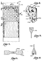
- Structure 110 comprises a corrugated plate 114 having alternating ridges and troughs 118 and 120, respectively, which extend in parallel relationship to each other. Construction of plate 114 is identical to construction to one of the plates 14 or 16 previously described for the preferred embodiment.
- a planar wall member 122 is disposed on one side of plate 114 with side edges 124 extending in an L-shaped configuration from the planar surface of the member so as to wrap around plate 114.
- Wall member 122 is preferably formed from a woven material such as aluminum, steel or other wire mesh; nylon, Teflon and other plastic materials; or cloth material such as cotton, fiberglass, polyester and the like.
- Member 122 is preferably sized to completely cover one side of plate 114 and a catalyst bed 22 as previously described for the preferred embodiment is located between member 122 and plate 114.
- the side edges of member 122 can be tack welded, riveted or otherwise rigidly secured to the side of plate 114 which is opposite the planar surface of the member so as to provide a unitary rigid construction.
- Member 122 and plate 114 cooperate to provide a plurality of enclosing, permeable envelopes 126 of triangular cross-section with two sides of the envelope being presented by the corrugated plate and the third side being presented by planar member 122.
- the edge portion of member 122 which extends at a 90° angle to the main planar surface of the member presents a wall for closing off the ends of each envelope 126.
- a plurality of plates 114 with catalyst in place are arranged in a manner previously described for structure 10. That is, a plurality of structures 110 are positioned in side-by-side parallel relationship with the ridges and troughs of one row of structures being rotated 90 relative to the plane of the structures on the next vertically adjoining row.
- the corrugated plates provide liquid flow channels 128 along the troughs 120 on the surface of the plate opposite catalyst bed 22. The liquid will, of course, extend over a substantial portion of the woven surface of the plate for mass transfer with the vapor phase. Also, some liquid stream may pass through the catalyst bed 22.
- Catalyst bed 22 forms a catalytic reaction zone for reacting the descending liquid streams. The vapor phase formed by fractional distillation of the liquid streams will flow upward through the catalyst as well as through channels 128 for interaction with the liquid streams including mass transfer.
- the liquid phase of the fluid streams flows through catalyst beds 22.
- the catalytically reacted products weep from the catalyst zone through the permeable plates 114 and wall member 122 for mass transfer in open channels 128.
- the vapor phase primarily flows through open channels 128 and mass transfer between the liquid and the vapor phases occurs. Some distillation may also occur within the catalyst bed 22 with the vapor phase which passes through the permeable plates 114 and wall member 120.
- Enclosing of the catalyst bed 22 in the envelopes presented by plate 114 and wall member 122 permits the desired distillation efficiency while accommodating reuse of the plates 112.
- structure 110 is removed from the column and one end of the enclosing envelopes is opened to allow the catalyst to be removed.
- the plate may then be inverted and new catalyst added through the same opening.
- FIGS. 7-11 Another alternative form of the invention is illustrated in FIGS. 7-11.
- This alternative form of the invention is designated generally by the numeral 210 and comprises a plurality of pairs of rigid plates 214 and 216.
- Each of the plates 214 and 216 is identical and, accordingly, only one will be described in detail.
- Plate 214 is provided with a plurality of spaced apart externally convex sections 230 each of which has a truncated pyramid shape with sloping sidewalls 230a that converge on a planar bottom 230b.
- the plate 214 also has a plurality of second externally convex sections 232 which are of semicylindrical shape and extend between adjacent sections 230.
- Plates 214 and 216 are preferably made from a vapor/liquid permeable material such as wire mesh, although other alternative materials as discussed in conjunction with the preferred embodiment may also be utilized.
- the externally convex sections 230 and 232 are aligned so as to present first and second open areas 234 and 236 as illustrated in FIGS. 9 and 11.
- the flat areas 238 of plate 214 which areas comprise the remainder of the plate surface not occupied by externally convex sections 230 and 232, are placed in contact with the corresponding area of a facing plate. These flat areas may be spot welded or otherwise connected to hold the two plates in rigid relationship thus adding considerable strength to the assembled pair of plates.
- the sections 230 at the end of plate 214 are further truncated along a plane lying perpendicular to the plane of the plate and when the two plates 214 and 216 are joined together in facing relationship end caps 240 close off the open areas at the terminal plate ends.
- the end cap 240 is made of the same material as plates 214 and 216. Cap 240 is flush with the ends of the assembled pair of plates.
- a second end cap 242 (FIG. 10) is used to close off the open areas at the ends of the assembled plates which are opposite the ends where caps 240 are employed. It is to be noted that end caps 242, which are made from the same material as plate 214, are spaced inwardly from the terminal ends of the two adjoining plates.
- the open areas of structure 210 are filled with particulate catalyst material, various alternatives for which are discussed in conjunction with the preferred embodiment.
- the plates are arranged in rows within column 212 as shown in FIG. 7 and as described in conjunction with the preferred embodiment. Also, as discussed in conjunction with the preferred embodiment, each vertical row of plates is preferably oriented at 90° relative to the vertical planes of the plates in an adjacent row.
Landscapes
- Chemical & Material Sciences (AREA)
- Chemical Kinetics & Catalysis (AREA)
- Organic Chemistry (AREA)
- Engineering & Computer Science (AREA)
- Materials Engineering (AREA)
- Physics & Mathematics (AREA)
- Thermal Sciences (AREA)
- Vaporization, Distillation, Condensation, Sublimation, And Cold Traps (AREA)
- Physical Or Chemical Processes And Apparatus (AREA)
- Devices And Processes Conducted In The Presence Of Fluids And Solid Particles (AREA)
- Organic Low-Molecular-Weight Compounds And Preparation Thereof (AREA)
Claims (11)
- Structure (10) pour assurer une réaction catalytique simultanée avec la distillation d'écoulements de fluide, la structure comprenant plusieurs plaques perméables aux vapeurs et aux liquides, s'étendant verticalement (14, 16), disposées en paires opposées et présentant plusieurs régions ouvertes entre les plaques de chaque paire; un lit de particules catalytiques (22) remplissant essentiellement au moins certaines des régions ouvertes; et des moyens pour retenir le catalyseur (24) dans les régions ouvertes; caractérisée en ce que chaque paire de plaques adjacentes est en contact avec au moins une paire voisine, pour présenter plusieurs paires contiguës de plaques, au moins l'une des plaques en contact de paires contiguës étant ondulée, de sorte que les paires contiguës présentent entre elles des canaux d'écoulement pour l'écoulement descendant de liquide et l'écoulement montant de vapeur.
- Structure (10) selon la revendication 1, dans laquelle les deux plaques (14, 16) d'une paire sont ondulées, et il existe des moyens (26) pour retenir les plaques en relation d'écartement pour présenter les régions, ces dernières comprenant plusieurs régions planes qui se coupent et qui sont parallèles aux plans des ondulations.
- Structure (10) selon la revendication 1, dans laquelle l'une des plaques (114) de la paire est ondulée et l'autre des plaques (122) comprend un organe présentant une surface essentiellement plane en contact avec les ondulations de la première plaque, pour présenter les régions ouvertes, chaque région ouverte présentant une section transversale triangulaire.
- Structure (10) en vue d'assurer une réaction catalytique simultanée avec la distillation d'écoulements de fluide, la structure comprenant plusieurs plaques perméables aux vapeurs et aux liquides, s'étendant verticalement (214, 216), disposées en paires opposées et présentant plusieurs régions ouvertes entre les plaques de chaque paire; un lit de particules catalytiques (22) remplissant essentiellement au moins certaines des régions ouvertes; et des moyens pour retenir le catalyseur (24) dans les régions ouvertes; caractérisée en ce que chaque paire de plaques adjacentes est en contact avec au moins une paire voisine, pour présenter plusieurs paires contiguës de plaques, les plaques en contact des paires contiguës présentant des tronçons extérieurement convexes (230) espacés l'un de l'autre, par lesquels les plaques en contact entrent en contact les uns avec les autres, de sorte que les paires contiguës présentent entre elles des canaux d'écoulement pour l'écoulement descendant de liquide et l'écoulement montant de vapeur.
- Structure (10) selon la revendication 4, dans laquelle chacune des plaques (214, 216) est caractérisée par plusieurs premiers tronçons (230) extérieurement convexes et écartés les uns des autres, les premiers tronçons étant alignés lorsque les plaques se font face, pour présenter certaines des régions ouvertes, les plaques étant en outre caractérisées par plusieurs tronçons extérieurement convexes (232), les seconds tronçons étant alignés lorsque les plaques se font face, pour présenter entre les régions des passages qui relient les régions présentées par les premiers tronçons.
- Colonne de transfert de masse (12) présentant une structure selon l'une quelconque des revendications précédentes, la colonne comportant des moyens pour présenter une tour verticale allongée dans laquelle des réactifs peuvent être introduits à différentes hauteurs verticales; plusieurs rangées verticalement espacées des paires de plaques étant présentes, chaque plaque s'étendant dans la section transversale de la tour.
- Procédé pour la mise en réaction catalytique simultanée avec la distillation d'écoulements de fluide dans une colonne de transfert de masse, le procédé comprenant les étapes consistant à prévoir plusieurs paires de plaques (14, 16) perméables aux vapeurs et aux liquides, s'étendant verticalement, qui présentent des zones de transfert de masse en vue d'une interaction liquide-vapeur et qui présentent, entre les faces de chaque paire, des régions ouvertes destinées à recevoir un catalyseur; prévoir un lit de particules catalytiques (22) dans les régions ouvertes, pour former une zone de réaction catalytique; introduire un écoulement de liquide dans la colonne; envoyer l'écoulement de liquide à travers la zone de réaction catalytique pour faire réagir catalytiquement l'écoulement de liquide; simultanément, distiller une partie de l'écoulement de liquide dans la colonne, pour présenter un écoulement de vapeur; envoyer l'écoulement de vapeur et l'écoulement de liquide vers les zones de transfert de masse, pour interaction; et extraire les produits de distillation du fluide et le produit de réaction hors des zones; caractérisé en ce que chaque paire adjacente de plaques est en contact avec au moins une paire voisine, pour présenter plusieurs paires contiguës de plaques, au moins l'une des plaques en contact de paires contiguës étant ondulée, de sorte que les paires contiguës présentent entre elles des canaux d'écoulement pour l'écoulement descendant de liquide et l'écoulement montant de vapeur.
- Procédé selon la revendication 8, dans lequel les deux plaques (14, 16) d'une paire sont ondulées et sont maintenues en relation d'écartement mutuel, pour présenter plusieurs régions ouvertes planes qui se coupent, lesquelles régions sont parallèles aux plans des ondulations.
- Procédé selon la revendication 7, dans lequel une plaque (114) de la paire est ondulée et l'autre plaque (122) présente une surface essentiellement plane en contact avec les ondulations du premier plaque, pour présenter plusieurs régions ouvertes, chaque région ouverte présentant une section transversale triangulaire.
- Procédé pour la mise en réaction catalytique simultanée avec la distillation d'écoulements de fluide dans une colonne de transfert de masse, le procédé comportant les étapes consistant à présenter plusieurs paires de plaques perméables aux vapeurs et aux liquides, s'étendant verticalement (14, 16), qui présentent des zones de transfert de masse en vue d'une interaction liquide-vapeur, et qui présentent entre les faces de chaque paire des régions ouvertes destinées à recevoir un catalyseur; prévoir un lit de particules catalytiques (22) dans les régions ouvertes, pour former une zone de réaction catalytique; introduire un écoulement de liquide dans la colonne; envoyer l'écoulement de liquide à travers la zone de réaction catalytique pour faire réagir catalytiquement l'écoulement de liquide; simultanément, distiller une partie de l'écoulement de liquide dans la colonne, pour présenter un écoulement de vapeur; envoyer l'écoulement de vapeur et l'écoulement de liquide vers les zones de transfert de masse, pour interaction; et extraire les produits de distillation du fluide et le produit de réaction des zones; caractérisé en ce que chaque paire de plaques voisines est en contact avec au moins une paire contiguë, pour fournir plusieurs paires de plaques contiguës, les plaques de contact de paires contiguës présentant des tronçons extérieurement convexes (230) écartés l'un de l'autre, par lesquels les plaques de contact entrent en contact l'une avec l'autre, de sorte que les paires contiguës présentent entre elles des canaux d'écoulement pour l'écoulement descendant de liquide et l'écoulement montant de vapeur.
- Procédé selon la revendication 10, dans lequel chacune des plaques (214, 216) est caractérisée par plusieurs premiers tronçons extérieurement convexes (230) écartés les uns des autres, les premiers tronçons étant alignés lorsque les plaques se font face, pour présenter certaines des régions ouvertes, les plaques étant en outre caractérisées par plusieurs seconds tronçons extérieurement convexes (232), les seconds tronçons étant alignés lorsque les plaques se font face, pour réaliser entre les régions des passages qui relient les régions présentées par les premiers tronçons.
Applications Claiming Priority (2)
| Application Number | Priority Date | Filing Date | Title |
|---|---|---|---|
| US07/434,342 US5073236A (en) | 1989-11-13 | 1989-11-13 | Process and structure for effecting catalytic reactions in distillation structure |
| US434342 | 1995-05-02 |
Publications (3)
| Publication Number | Publication Date |
|---|---|
| EP0428265A1 EP0428265A1 (fr) | 1991-05-22 |
| EP0428265B1 EP0428265B1 (fr) | 1997-02-26 |
| EP0428265B2 true EP0428265B2 (fr) | 2000-05-17 |
Family
ID=23723834
Family Applications (1)
| Application Number | Title | Priority Date | Filing Date |
|---|---|---|---|
| EP90311157A Expired - Lifetime EP0428265B2 (fr) | 1989-11-13 | 1990-10-11 | Procédé et structure pour la réalisation de réactions catalytiques dans des structures de distillation |
Country Status (9)
| Country | Link |
|---|---|
| US (1) | US5073236A (fr) |
| EP (1) | EP0428265B2 (fr) |
| JP (1) | JPH0729047B2 (fr) |
| AU (1) | AU625448B2 (fr) |
| CA (1) | CA2027512C (fr) |
| DK (1) | DK0428265T4 (fr) |
| ES (1) | ES2098255T5 (fr) |
| GR (2) | GR3023363T3 (fr) |
| MX (1) | MX166294B (fr) |
Families Citing this family (119)
| Publication number | Priority date | Publication date | Assignee | Title |
|---|---|---|---|---|
| US5948211A (en) * | 1990-02-06 | 1999-09-07 | Koch-Glitsch, Inc. | Distillation column downcomer having liquid permeable wall |
| US5108550A (en) * | 1990-02-06 | 1992-04-28 | Koch Engineering Company, Inc. | Catalyst system for distillation reactor |
| US5593548A (en) * | 1990-02-06 | 1997-01-14 | Koch Engineering Company, Inc. | Method for concurrent reaction with distillation |
| US5855741A (en) * | 1990-02-06 | 1999-01-05 | Koch Engineering Company, Inc. | Apparatus for concurrent reaction with distillation |
| US5454913A (en) * | 1990-02-06 | 1995-10-03 | Koch Engineering Company, Inc. | Internals for distillation columns including those for use in catalytic reactions |
| US5447609A (en) * | 1990-02-06 | 1995-09-05 | Koch Engineering Company, Inc. | Catalytic reaction and mass transfer process |
| FR2671492B1 (fr) * | 1991-01-11 | 1994-07-22 | Benzaria Jacques | Conteneur pour materiaux solides granulaires, sa fabrication et ses applications notamment en catalyse et en adsorption. |
| DE69200154T2 (de) * | 1991-03-08 | 1994-09-15 | Inst Francais Du Petrol | Destillations-Reaktionsvorrichtung und ihre Verwendung. |
| GB9124087D0 (en) * | 1991-11-13 | 1992-01-02 | Ici Plc | Chemical process |
| ES2179823T3 (es) * | 1991-09-05 | 2003-02-01 | Abbott Lab | Inmunosupresor macrolido. |
| GB9211534D0 (en) * | 1992-06-01 | 1992-07-15 | Pgp Ind Inc | Foraminous sheets for use in catalysis |
| US5254318A (en) * | 1992-07-20 | 1993-10-19 | Stone & Webster Engineering Corporation | Lined reformer tubes for high pressure reformer reactors |
| US5308451A (en) * | 1992-11-02 | 1994-05-03 | Uop | Fractionation tray for catalytic distillation |
| EP0618003B1 (fr) * | 1993-03-25 | 1999-01-07 | Sulzer Chemtech AG | Elément de remplissage destiné à l'échange ou à la transformation de matière sous la forme d'un élément d'échange de chaleur |
| US5348710A (en) * | 1993-06-11 | 1994-09-20 | Johnson Kenneth H | Catalytic distillation structure |
| DE59307946D1 (de) * | 1993-06-30 | 1998-02-12 | Sulzer Chemtech Ag | Katalysierender Festbettreaktor |
| US5321163A (en) * | 1993-09-09 | 1994-06-14 | Chemical Research & Licensing Company | Multi-purpose catalytic distillation column and eterification process using same |
| US5714640A (en) * | 1994-01-21 | 1998-02-03 | Mobil Oil Corporation | Vapor pocket reactor |
| US5431890A (en) * | 1994-01-31 | 1995-07-11 | Chemical Research & Licensing Company | Catalytic distillation structure |
| HUT71029A (en) * | 1994-03-04 | 1995-11-28 | Glitsch | Chemical process tower, catalytic unit and method for locating of contact substance |
| US5449501A (en) * | 1994-03-29 | 1995-09-12 | Uop | Apparatus and process for catalytic distillation |
| CZ86495A3 (en) * | 1994-04-11 | 1995-11-15 | Scambia Ind Dev Ag | Catalyst means for catalytic treatment of exhaust gases, the catalyst as such and process for producing the catalyst means |
| US5461178A (en) * | 1994-04-28 | 1995-10-24 | Mobil Oil Corporation | Catalytic stripping of hydrocarbon liquid |
| US5510568A (en) * | 1994-06-17 | 1996-04-23 | Chemical Research & Licensing Company | Process for the removal of mercaptans and hydrogen sulfide from hydrocarbon streams |
| US5523062A (en) * | 1994-11-03 | 1996-06-04 | Chemical Research & Licening Company | Catalytic distillation distribution structure |
| US5792432A (en) † | 1994-11-15 | 1998-08-11 | Babcock-Hitachi Kabushiki Kaisha | Catalyst unit and gas purifying apparatus |
| US5554275A (en) * | 1994-11-28 | 1996-09-10 | Mobil Oil Corporation | Catalytic hydrodesulfurization and stripping of hydrocarbon liquid |
| US5779883A (en) * | 1995-07-10 | 1998-07-14 | Catalytic Distillation Technologies | Hydrodesulfurization process utilizing a distillation column realtor |
| US5817906A (en) * | 1995-08-10 | 1998-10-06 | Uop Llc | Process for producing light olefins using reaction with distillation as an intermediate step |
| US5961815A (en) * | 1995-08-28 | 1999-10-05 | Catalytic Distillation Technologies | Hydroconversion process |
| US5597476A (en) * | 1995-08-28 | 1997-01-28 | Chemical Research & Licensing Company | Gasoline desulfurization process |
| FR2743079B1 (fr) | 1995-12-27 | 1998-02-06 | Inst Francais Du Petrole | Procede et dispositif d'hydrogenation selective par distillation catalytique comportant une zone reactionnelle a co-courant ascendant liquide-gaz |
| FR2743080B1 (fr) | 1995-12-27 | 1998-02-06 | Inst Francais Du Petrole | Procede de reduction selective de la teneur en benzene et en composes insatures legers d'une coupe d'hydrocarbures |
| FR2743081B1 (fr) | 1995-12-27 | 1998-01-30 | Inst Francais Du Petrole | Procede de reduction selective de la teneur en benzene et en composes insatures legers d'une coupe d'hydrocarbures |
| US5730843A (en) * | 1995-12-29 | 1998-03-24 | Chemical Research & Licensing Company | Catalytic distillation structure |
| FR2744458B1 (fr) | 1996-02-05 | 1998-03-27 | Inst Francais Du Petrole | Procede d'isomerisation de paraffines par distillation reactive |
| US5628880A (en) * | 1996-02-12 | 1997-05-13 | Chemical Research & Licensing Company | Etherification--hydrogenation process |
| DE19615886C1 (de) * | 1996-04-22 | 1997-07-31 | Huels Chemische Werke Ag | Verfahren zur Herstellung von rohem Dimethylterephthalat |
| DE19624130A1 (de) * | 1996-06-17 | 1997-12-18 | Basf Ag | Verfahren zur katalytischen Destillation |
| US5683493A (en) * | 1996-07-19 | 1997-11-04 | Stober; Berne K. | Packing for separation columns and process of use |
| US5856602A (en) * | 1996-09-09 | 1999-01-05 | Catalytic Distillation Technologies | Selective hydrogenation of aromatics contained in hydrocarbon streams |
| US5807477A (en) * | 1996-09-23 | 1998-09-15 | Catalytic Distillation Technologies | Process for the treatment of light naphtha hydrocarbon streams |
| US5837130A (en) * | 1996-10-22 | 1998-11-17 | Catalytic Distillation Technologies | Catalytic distillation refining |
| DE19701045C2 (de) * | 1997-01-15 | 2001-03-01 | Andrzej Gorak | Strukturierte Mehrzweckpackung |
| US6045762A (en) * | 1997-01-22 | 2000-04-04 | Governors Of The University Of Alberta | Apparatus for catalytic distillation |
| US5916492A (en) * | 1997-03-27 | 1999-06-29 | Dow Corning Corporation | Structured packing containing liquid-vapor contact column |
| US6565816B1 (en) | 1997-06-25 | 2003-05-20 | Koch-Glitsch, Inc. | Saddle structure for reactive distillation |
| US6299845B1 (en) | 1997-08-08 | 2001-10-09 | Uop Llc | Catalytic distillation with in situ catalyst replacement |
| TW396052B (en) * | 1997-11-12 | 2000-07-01 | Babcock Hitachi Kk | Exhaust emission control catalyst element, catalyst structure, production method thereof, exhaust emission control apparatus and exhaust emission control method using the apparatus |
| US6277340B1 (en) | 1998-01-02 | 2001-08-21 | Abb Lummus Global, Inc. | Structured packing and element therefor |
| FR2777013B1 (fr) * | 1998-04-06 | 2000-05-05 | Inst Francais Du Petrole | Procede de conversion d'hydrocarbures par traitement dans une zone de distillation comprenant un reflux circulant, associee a une zone reactionnelle et son utilisation en hydrogenation du benzene |
| FR2777012B1 (fr) | 1998-04-06 | 2000-08-25 | Inst Francais Du Petrole | Procede de conversion d'hydrocarbures par traitement dans une zone de distillation comprenant le soutirage d'un distillat stabilise, associee a une zone reactionnelle, et son utilisation en hydrogenation du benzene |
| DE29807007U1 (de) * | 1998-04-18 | 1998-07-30 | Górak, Andrzej, Prof. Dr.-Ing., 58454 Witten | Packung für Stoffaustauschkolonnen |
| FR2782322B1 (fr) | 1998-08-17 | 2000-10-06 | Inst Francais Du Petrole | Procede de conversion d'hydrocarbures par traitement dans une zone de distillation comprenant le soutirage lateral d'une coupe d'hydrocarbures, associee a une zone reactionnelle et son utilisation en hydrogenation du benzene |
| AU761031B2 (en) * | 1998-09-09 | 2003-05-29 | Babcock-Hitachi Kabushiki Kaisha | Exhaust emission control catalyst structure and device |
| US6083378A (en) * | 1998-09-10 | 2000-07-04 | Catalytic Distillation Technologies | Process for the simultaneous treatment and fractionation of light naphtha hydrocarbon streams |
| DE19860146A1 (de) | 1998-12-24 | 2000-06-29 | Bayer Ag | Verfahren und Anlage zur Herstellung von Silan |
| JP2002535296A (ja) * | 1999-01-21 | 2002-10-22 | エイビービー ラマス グローバル インコーポレイテッド | 選択的水素添加プロセスとその触媒 |
| US6242661B1 (en) | 1999-07-16 | 2001-06-05 | Catalytic Distillation Technologies | Process for the separation of isobutene from normal butenes |
| US20030012711A1 (en) * | 1999-11-17 | 2003-01-16 | Conoco Inc. | Honeycomb monolith catalyst support for catalytic distillation reactor |
| DE50101102D1 (de) | 2000-04-04 | 2004-01-22 | Sulzer Chemtech Ag Winterthur | Geordnete Kolonnenpackung mit einer Feinstrukturierung |
| EP1145761B1 (fr) * | 2000-04-04 | 2003-12-10 | Sulzer Chemtech AG | Garnissage de colonne ordonée ayant une structure fine |
| FR2807337B1 (fr) * | 2000-04-11 | 2002-07-05 | Packinox Sa | Grille de maintien d'un catalyseur dans un faisceau de plaques d'un reacteur catalytique |
| FR2807676B1 (fr) * | 2000-04-17 | 2002-07-12 | Inst Francais Du Petrole | Sous-ensemble polyfonctionnel assurant la mise en contact, la distribution de matiere et l'echange de chaleur et/ou de matiere d'au moins une phase gazeuse et d'au moins une phase liquide |
| FR2812221B1 (fr) * | 2000-07-28 | 2003-04-04 | Butachimie | Nouveau dispositif catalytique pour la mise en oeuvre d'une reaction en milieu gazeux a haute temperature |
| US6416659B1 (en) | 2000-08-17 | 2002-07-09 | Catalytic Distillation Technologies | Process for the production of an ultra low sulfur |
| DE10050625A1 (de) * | 2000-10-12 | 2002-04-18 | Erdoelchemie Gmbh | Strukturierte Mehrzweckpackungen und deren Verwendung |
| DE10102082A1 (de) | 2000-10-19 | 2002-05-02 | Oxeno Olefinchemie Gmbh | Verfahren zur Herstellung von hochreinem Raffinat II und Methyl-tert.-butylether |
| SE520006C2 (sv) * | 2001-09-20 | 2003-05-06 | Catator Ab | Anordning, metod vid tillverkning och metod vid genomförande av katalytiska reaktioner i plattvärmeväxlare |
| EP1323467A1 (fr) * | 2001-12-20 | 2003-07-02 | Rolf P. C. Manteufel | Procédé et dispositif d'échange de matière et/ou d'énergie dans une colonne de lavage |
| US20040000474A1 (en) * | 2002-02-22 | 2004-01-01 | Catalytic Distillation Technologies | Liquid-continuous column distillation |
| US6824676B1 (en) | 2002-03-08 | 2004-11-30 | Catalytic Distillation Technologies | Process for the selective desulfurization of a mid range gasoline cut |
| DE10238370A1 (de) | 2002-08-22 | 2004-03-04 | Oxeno Olefinchemie Gmbh | Verfahren zur Herstellung von Isobuten aus technischen Methyl-tert.-butylether |
| US6855853B2 (en) * | 2002-09-18 | 2005-02-15 | Catalytic Distillation Technologies | Process for the production of low benzene gasoline |
| US6984312B2 (en) * | 2002-11-22 | 2006-01-10 | Catalytic Distillation Technologies | Process for the desulfurization of light FCC naphtha |
| TWI324592B (en) * | 2002-11-28 | 2010-05-11 | Sulzer Chemtech Ag | A method for the esterification of a fatty acid |
| EP1424115B1 (fr) * | 2002-11-28 | 2016-01-13 | Sulzer Chemtech AG | Procédé d'estérification d'un acide gras |
| FR2867697B1 (fr) * | 2004-03-16 | 2007-06-01 | Air Liquide | Structure de garnissage ondule-croise |
| US7332132B2 (en) * | 2004-03-19 | 2008-02-19 | Uop Llc | Stripping apparatus and process |
| DE102006040430B4 (de) | 2006-08-29 | 2022-06-15 | Evonik Operations Gmbh | Verfahren zur Spaltung von MTBE |
| ES2356488T3 (es) * | 2006-09-19 | 2011-04-08 | Basf Se | Procedimiento para la obtención de cloro en un reactor de lecho fluidizado. |
| PL2066436T3 (pl) * | 2006-09-19 | 2012-12-31 | Basf Se | Reaktor fluidyzacyjny do prowadzenia reakcji w fazie gazowej |
| PT2069283E (pt) * | 2006-09-19 | 2010-08-03 | Basf Se | Método para a produção de aminas aromáticas num reactor de leito fluidizado |
| US20080146856A1 (en) * | 2006-12-19 | 2008-06-19 | Leyshon David W | Propylene production |
| US7816572B2 (en) * | 2007-08-07 | 2010-10-19 | Lyondell Chemical Technology, L.P. | Propylene and isoprene production |
| US7649123B2 (en) * | 2008-01-15 | 2010-01-19 | Catalytic Distillation Technologies | Propylene oligomerization process |
| US20090183981A1 (en) * | 2008-01-23 | 2009-07-23 | Catalytic Distillation Technologies | Integrated pyrolysis gasoline treatment process |
| US8236172B2 (en) | 2008-01-25 | 2012-08-07 | Catalytic Distillation Technologies | Process to hydrodesulfurize FCC gasoline resulting in a low-mercaptan product |
| US8043495B2 (en) * | 2008-01-25 | 2011-10-25 | Catalytic Distillation Technologies | Process to hydrodesulfurize FCC gasoline resulting in a low-mercaptan product |
| US7927480B2 (en) * | 2008-01-29 | 2011-04-19 | Catalytic Distillation Technologies | Process for desulfurization of cracked naphtha |
| DE102008007081B4 (de) | 2008-01-31 | 2018-12-06 | Evonik Degussa Gmbh | Verfahren zur Herstellung von n-Buten-Oligomeren und 1-Buten aus technischen Mischungen I von C4-Kohlenwasserstoffen |
| US8357291B2 (en) * | 2008-02-11 | 2013-01-22 | Exxonmobil Upstream Research Company | Upgrading bitumen in a paraffinic froth treatment process |
| US8143466B2 (en) * | 2008-02-26 | 2012-03-27 | Catalytic Distillation Technologies | Process for benzene removal from gasoline |
| US8471082B2 (en) * | 2008-03-14 | 2013-06-25 | Catalytic Distillation Technologies | Process for converting methane to ethylene |
| US9315741B2 (en) * | 2008-09-08 | 2016-04-19 | Catalytic Distillation Technologies | Process for ultra low benzene reformate using catalytic distillation |
| US8298412B2 (en) * | 2008-09-17 | 2012-10-30 | Koch-Glitsch, Lp | Structured packing module for mass transfer column and process involving same |
| EP2208719A1 (fr) | 2009-01-15 | 2010-07-21 | Sasol Solvents Germany GmbH | Procédé de production d'alcools inférieurs par hydratation d'oléfine |
| AR075787A1 (es) | 2009-03-05 | 2011-04-27 | Uhde Gmbh | Procedimiento y dispositivo para retener el catalizador en forma de particulas arrastradas ingresantes |
| DE102009011375A1 (de) * | 2009-03-05 | 2010-09-23 | Uhde Gmbh | Verfahren zur Niederhaltung von angeströmten Katalysatorpartikeln |
| US8395002B2 (en) * | 2009-03-09 | 2013-03-12 | Catalytic Distillation Technologies | Use of catalytic distillation for benzene separation and purification |
| DE102009027404A1 (de) | 2009-07-01 | 2011-01-05 | Evonik Oxeno Gmbh | Herstellung von Isobuten durch Spaltung von MTBE |
| US8486258B2 (en) | 2010-04-01 | 2013-07-16 | Catalytic Distillation Technologies | Gasoline hydrodesulfurization and membrane unit to reduce mercaptan type sulfur |
| DE102010028788B4 (de) | 2010-05-10 | 2022-03-31 | Tutech Innovation Gmbh | Ein in der Reaktivrektifikation einsetzbarer, einen Biokatalysator aufweisender Kolonneneinbau und dessen Verwendung in der Reaktivrektifikation |
| US8628656B2 (en) | 2010-08-25 | 2014-01-14 | Catalytic Distillation Technologies | Hydrodesulfurization process with selected liquid recycle to reduce formation of recombinant mercaptans |
| US20170021285A1 (en) * | 2012-02-03 | 2017-01-26 | Mann+Hummel Gmbh | Ion exchange exoskeleton and filter assembly |
| CN104549121A (zh) * | 2014-12-23 | 2015-04-29 | 天津大学 | 用于反歧化反应精馏塔制备三氯氢硅的结构催化填料 |
| CN107428712A (zh) | 2015-01-14 | 2017-12-01 | 赢创德固赛有限公司 | 用于制备氧化丙烯和烷基叔丁基醚的整合方法 |
| CN107428711A (zh) | 2015-01-14 | 2017-12-01 | 赢创德固赛有限公司 | 制备环氧丙烯和烷基叔丁基醚的集成方法 |
| CN104587945A (zh) * | 2015-01-24 | 2015-05-06 | 福州大学 | 一种催化精馏塔塔内规整催化填料及其制备方法 |
| US10066173B2 (en) | 2015-10-07 | 2018-09-04 | Shell Oil Company | Method of processing cracked naphtha to make a low-sulfur naphtha product and ultra-low sulfur diesel |
| US10214698B2 (en) | 2015-10-07 | 2019-02-26 | Shell Oil Company | Method of processing cracked naphtha to make a low-sulfur naphtha product |
| US10953382B2 (en) * | 2017-06-09 | 2021-03-23 | Koch-Glitsch, Lp | Structured packing module for mass transfer columns |
| CN107519824B (zh) * | 2017-10-10 | 2023-09-15 | 天津市新天进科技开发有限公司 | 一种复合式高通量催化蒸馏塔构件 |
| US11358115B2 (en) | 2018-03-28 | 2022-06-14 | Norell, Inc. | Multi-channel distillation column packing |
| AU2019251001B2 (en) | 2018-04-11 | 2022-03-31 | Lummus Technology Llc | Structured packing for catalytic distillation |
| WO2020041696A1 (fr) | 2018-08-23 | 2020-02-27 | Lummus Technology Llc | Procédé de production d'isobutylène de haute pureté |
| CN111116180A (zh) * | 2020-02-12 | 2020-05-08 | 江西车田科技有限公司 | 一种整体网状微孔陶瓷波纹填料及制造方法 |
| CN112403431A (zh) * | 2020-10-27 | 2021-02-26 | 中国科学院过程工程研究所 | 一种波型撑板及塔设备与应用 |
| EP4484000A1 (fr) * | 2023-06-29 | 2025-01-01 | Sulzer Management AG | Élément d'emballage à canaux croisés structurés pour des applications sensibles à l'encrassement et à la corrosion |
Citations (2)
| Publication number | Priority date | Publication date | Assignee | Title |
|---|---|---|---|---|
| EP0008860A1 (fr) † | 1978-07-27 | 1980-03-19 | CHEMICAL RESEARCH & LICENSING COMPANY | Système catalytique |
| US4731229A (en) † | 1985-05-14 | 1988-03-15 | Sulzer Brothers Limited | Reactor and packing element for catalyzed chemical reactions |
Family Cites Families (17)
| Publication number | Priority date | Publication date | Assignee | Title |
|---|---|---|---|---|
| US2676875A (en) * | 1942-06-16 | 1954-04-27 | Atomic Energy Commission | Catalytic apparatus for isotope exchange |
| FR1377537A (fr) * | 1963-09-26 | 1964-11-06 | Tissmetal Lionel Dupont | élément de garnissage pour colonnes d'échange entre deux fluides |
| DE1904144C3 (de) * | 1969-01-28 | 1974-01-31 | Linde Ag, 6200 Wiesbaden | Vorrichtung zum Inkontaktbringen von Gasen mit Flüssigkeiten |
| CH617357A5 (fr) * | 1977-05-12 | 1980-05-30 | Sulzer Ag | |
| US4302356A (en) * | 1978-07-27 | 1981-11-24 | Chemical Research & Licensing Co. | Process for separating isobutene from C4 streams |
| US4242530A (en) * | 1978-07-27 | 1980-12-30 | Chemical Research & Licensing Company | Process for separating isobutene from C4 streams |
| US4307254A (en) * | 1979-02-21 | 1981-12-22 | Chemical Research & Licensing Company | Catalytic distillation process |
| US4213847A (en) * | 1979-05-16 | 1980-07-22 | Mobil Oil Corporation | Catalytic dewaxing of lubes in reactor fractionator |
| US4303600A (en) * | 1981-01-08 | 1981-12-01 | The Munters Corporation | Reactor column |
| US4443559A (en) * | 1981-09-30 | 1984-04-17 | Chemical Research & Licensing Company | Catalytic distillation structure |
| US4439350A (en) * | 1982-06-21 | 1984-03-27 | Chemical Research & Licensing Company | Contact structure for use in catalytic distillation |
| US4471154A (en) * | 1983-06-10 | 1984-09-11 | Chevron Research Company | Staged, fluidized-bed distillation-reactor and a process for using such reactor |
| JPS601401U (ja) * | 1983-06-16 | 1985-01-08 | 積水樹脂株式会社 | 物質交換塔、熱交換塔などの充填材 |
| MX168173B (es) * | 1983-06-21 | 1993-05-07 | Glitsch | Empaque de metal foraminado y metodo para manufacturarlo |
| EP0151693B1 (fr) * | 1983-12-15 | 1990-01-17 | GebràDer Sulzer Aktiengesellschaft | Colonne d'échange de matière |
| JPS63197533A (ja) * | 1987-12-28 | 1988-08-16 | ケミカル・リサーチ・アンド・ライセンシング・カンパニー | 接触蒸留用触媒構造物 |
| FR2628418B1 (fr) * | 1988-03-08 | 1991-01-04 | Inst Francais Du Petrole | Procede de preparation d'un ether alkylique tertiaire par distillation reactive |
-
1989
- 1989-11-13 US US07/434,342 patent/US5073236A/en not_active Expired - Lifetime
-
1990
- 1990-10-11 ES ES90311157T patent/ES2098255T5/es not_active Expired - Lifetime
- 1990-10-11 EP EP90311157A patent/EP0428265B2/fr not_active Expired - Lifetime
- 1990-10-11 DK DK90311157T patent/DK0428265T4/da active
- 1990-10-12 CA CA002027512A patent/CA2027512C/fr not_active Expired - Lifetime
- 1990-10-22 AU AU64874/90A patent/AU625448B2/en not_active Ceased
- 1990-11-12 MX MX023286A patent/MX166294B/es unknown
- 1990-11-13 JP JP2304195A patent/JPH0729047B2/ja not_active Expired - Fee Related
-
1997
- 1997-05-09 GR GR970401015T patent/GR3023363T3/el unknown
-
2000
- 2000-08-17 GR GR20000401907T patent/GR3034222T3/el not_active IP Right Cessation
Patent Citations (2)
| Publication number | Priority date | Publication date | Assignee | Title |
|---|---|---|---|---|
| EP0008860A1 (fr) † | 1978-07-27 | 1980-03-19 | CHEMICAL RESEARCH & LICENSING COMPANY | Système catalytique |
| US4731229A (en) † | 1985-05-14 | 1988-03-15 | Sulzer Brothers Limited | Reactor and packing element for catalyzed chemical reactions |
Non-Patent Citations (1)
| Title |
|---|
| Chemical Processing, Febr. 1987, pages 27-30 † |
Also Published As
| Publication number | Publication date |
|---|---|
| JPH0729047B2 (ja) | 1995-04-05 |
| ES2098255T3 (es) | 1997-05-01 |
| CA2027512C (fr) | 2002-03-12 |
| AU625448B2 (en) | 1992-07-09 |
| JPH03178334A (ja) | 1991-08-02 |
| GR3023363T3 (en) | 1997-08-29 |
| EP0428265A1 (fr) | 1991-05-22 |
| MX166294B (es) | 1992-12-28 |
| DK0428265T4 (da) | 2000-09-18 |
| DK0428265T3 (da) | 1997-08-04 |
| ES2098255T5 (es) | 2000-10-16 |
| EP0428265B1 (fr) | 1997-02-26 |
| CA2027512A1 (fr) | 1991-05-14 |
| AU6487490A (en) | 1991-05-16 |
| US5073236A (en) | 1991-12-17 |
| GR3034222T3 (en) | 2000-12-29 |
Similar Documents
| Publication | Publication Date | Title |
|---|---|---|
| EP0428265B2 (fr) | Procédé et structure pour la réalisation de réactions catalytiques dans des structures de distillation | |
| AU674596B2 (en) | Catalytic distillation structure | |
| EP0665041B1 (fr) | Structure de distillation catalytique | |
| US5291989A (en) | Catalyst system for distillation reactor | |
| RU96102598A (ru) | Каталитическая дистилляционная структура | |
| US5523062A (en) | Catalytic distillation distribution structure | |
| US5496446A (en) | Internals for distillation columns including those for use in catalytic reactions | |
| EP0664722B1 (fr) | Structure de reaction catalytique et de transfert de masse et procede utilisant une telle structure | |
| US6110326A (en) | Method for concurrent reaction and distillation of fluid streams | |
| US6286818B1 (en) | Internal members for mass transfer columns | |
| US5593548A (en) | Method for concurrent reaction with distillation | |
| US7267329B2 (en) | Alternating conventional and high capacity packing within the same section of an exchange column | |
| NZ236989A (en) | Reaction and distillation column having catalytic bed retained between corrugated plate pairs, and extended open areas | |
| US5942456A (en) | Multi-functional catalytic distillation structure | |
| CN112074587B (zh) | 用于催化蒸馏的结构填料 | |
| KR0136086B1 (ko) | 효과적인 촉매반응 및 증류방법과 구조물 | |
| CA2164974C (fr) | Structure de distillation catalytique | |
| EP0888156B1 (fr) | Procede et appareil a reaction et distillation concurrentes | |
| EP0664721B1 (fr) | Procede et appareil pour obtenir une reaction accompagnee simultanement d'une distillation |
Legal Events
| Date | Code | Title | Description |
|---|---|---|---|
| PUAI | Public reference made under article 153(3) epc to a published international application that has entered the european phase |
Free format text: ORIGINAL CODE: 0009012 |
|
| AK | Designated contracting states |
Kind code of ref document: A1 Designated state(s): AT BE CH DE DK ES FR GB GR IT LI LU NL SE |
|
| 17P | Request for examination filed |
Effective date: 19911115 |
|
| 17Q | First examination report despatched |
Effective date: 19920928 |
|
| RBV | Designated contracting states (corrected) |
Designated state(s): DK ES GR |
|
| REG | Reference to a national code |
Ref country code: DE Ref legal event code: 8566 |
|
| GRAG | Despatch of communication of intention to grant |
Free format text: ORIGINAL CODE: EPIDOS AGRA |
|
| GRAH | Despatch of communication of intention to grant a patent |
Free format text: ORIGINAL CODE: EPIDOS IGRA |
|
| RBV | Designated contracting states (corrected) |
Designated state(s): DK ES GR LU |
|
| GRAH | Despatch of communication of intention to grant a patent |
Free format text: ORIGINAL CODE: EPIDOS IGRA |
|
| GRAA | (expected) grant |
Free format text: ORIGINAL CODE: 0009210 |
|
| AK | Designated contracting states |
Kind code of ref document: B1 Designated state(s): DK ES GR LU |
|
| REG | Reference to a national code |
Ref country code: ES Ref legal event code: FG2A Ref document number: 2098255 Country of ref document: ES Kind code of ref document: T3 |
|
| REG | Reference to a national code |
Ref country code: GR Ref legal event code: FG4A Free format text: 3023363 |
|
| REG | Reference to a national code |
Ref country code: DK Ref legal event code: T3 |
|
| PLBQ | Unpublished change to opponent data |
Free format text: ORIGINAL CODE: EPIDOS OPPO |
|
| PLBI | Opposition filed |
Free format text: ORIGINAL CODE: 0009260 |
|
| 26 | Opposition filed |
Opponent name: CHEMICAL RESEARCH AND LICENSING COMPANY Effective date: 19971126 |
|
| PLBF | Reply of patent proprietor to notice(s) of opposition |
Free format text: ORIGINAL CODE: EPIDOS OBSO |
|
| PLBF | Reply of patent proprietor to notice(s) of opposition |
Free format text: ORIGINAL CODE: EPIDOS OBSO |
|
| PLBF | Reply of patent proprietor to notice(s) of opposition |
Free format text: ORIGINAL CODE: EPIDOS OBSO |
|
| RAP2 | Party data changed (patent owner data changed or rights of a patent transferred) |
Owner name: KOCH-GLITSCH, INC |
|
| PLBQ | Unpublished change to opponent data |
Free format text: ORIGINAL CODE: EPIDOS OPPO |
|
| PLAB | Opposition data, opponent's data or that of the opponent's representative modified |
Free format text: ORIGINAL CODE: 0009299OPPO |
|
| PLAW | Interlocutory decision in opposition |
Free format text: ORIGINAL CODE: EPIDOS IDOP |
|
| R26 | Opposition filed (corrected) |
Opponent name: CHEMICAL RESEARCH AND LICENSING COMPANY Effective date: 19971126 |
|
| PLAW | Interlocutory decision in opposition |
Free format text: ORIGINAL CODE: EPIDOS IDOP |
|
| PUAH | Patent maintained in amended form |
Free format text: ORIGINAL CODE: 0009272 |
|
| STAA | Information on the status of an ep patent application or granted ep patent |
Free format text: STATUS: PATENT MAINTAINED AS AMENDED |
|
| 27A | Patent maintained in amended form |
Effective date: 20000517 |
|
| AK | Designated contracting states |
Kind code of ref document: B2 Designated state(s): DK ES GR LU |
|
| PG25 | Lapsed in a contracting state [announced via postgrant information from national office to epo] |
Ref country code: GR Free format text: THE PATENT HAS BEEN ANNULLED BY A DECISION OF A NATIONAL AUTHORITY Effective date: 20000817 |
|
| REG | Reference to a national code |
Ref country code: DK Ref legal event code: T4 |
|
| EN | Fr: translation not filed | ||
| REG | Reference to a national code |
Ref country code: ES Ref legal event code: DC2A Kind code of ref document: T5 Effective date: 20000816 |
|
| PGFP | Annual fee paid to national office [announced via postgrant information from national office to epo] |
Ref country code: LU Payment date: 20011009 Year of fee payment: 12 |
|
| PGFP | Annual fee paid to national office [announced via postgrant information from national office to epo] |
Ref country code: DK Payment date: 20011012 Year of fee payment: 12 |
|
| PGFP | Annual fee paid to national office [announced via postgrant information from national office to epo] |
Ref country code: GR Payment date: 20011025 Year of fee payment: 12 |
|
| PG25 | Lapsed in a contracting state [announced via postgrant information from national office to epo] |
Ref country code: LU Free format text: LAPSE BECAUSE OF NON-PAYMENT OF DUE FEES Effective date: 20021011 |
|
| PG25 | Lapsed in a contracting state [announced via postgrant information from national office to epo] |
Ref country code: DK Free format text: LAPSE BECAUSE OF NON-PAYMENT OF DUE FEES Effective date: 20021031 |
|
| REG | Reference to a national code |
Ref country code: DK Ref legal event code: EBP |
|
| PGFP | Annual fee paid to national office [announced via postgrant information from national office to epo] |
Ref country code: ES Payment date: 20051129 Year of fee payment: 16 |
|
| REG | Reference to a national code |
Ref country code: ES Ref legal event code: FD2A Effective date: 20061013 |
|
| PG25 | Lapsed in a contracting state [announced via postgrant information from national office to epo] |
Ref country code: ES Free format text: LAPSE BECAUSE OF NON-PAYMENT OF DUE FEES Effective date: 20061013 |