EP0428384A2 - Réseau universel pour système magnétique-électronique de surveillance d'articles - Google Patents
Réseau universel pour système magnétique-électronique de surveillance d'articles Download PDFInfo
- Publication number
- EP0428384A2 EP0428384A2 EP90312381A EP90312381A EP0428384A2 EP 0428384 A2 EP0428384 A2 EP 0428384A2 EP 90312381 A EP90312381 A EP 90312381A EP 90312381 A EP90312381 A EP 90312381A EP 0428384 A2 EP0428384 A2 EP 0428384A2
- Authority
- EP
- European Patent Office
- Prior art keywords
- coil
- assembly
- chassis
- section
- frame
- Prior art date
- Legal status (The legal status is an assumption and is not a legal conclusion. Google has not performed a legal analysis and makes no representation as to the accuracy of the status listed.)
- Granted
Links
Images


Classifications
-
- E—FIXED CONSTRUCTIONS
- E06—DOORS, WINDOWS, SHUTTERS, OR ROLLER BLINDS IN GENERAL; LADDERS
- E06B—FIXED OR MOVABLE CLOSURES FOR OPENINGS IN BUILDINGS, VEHICLES, FENCES OR LIKE ENCLOSURES IN GENERAL, e.g. DOORS, WINDOWS, BLINDS, GATES
- E06B9/00—Screening or protective devices for wall or similar openings, with or without operating or securing mechanisms; Closures of similar construction
- E06B9/02—Shutters, movable grilles, or other safety closing devices, e.g. against burglary
-
- G—PHYSICS
- G08—SIGNALLING
- G08B—SIGNALLING SYSTEMS, e.g. PERSONAL CALLING SYSTEMS; ORDER TELEGRAPHS; ALARM SYSTEMS
- G08B13/00—Burglar, theft or intruder alarms
- G08B13/22—Electrical actuation
- G08B13/24—Electrical actuation by interference with electromagnetic field distribution
- G08B13/2402—Electronic Article Surveillance [EAS], i.e. systems using tags for detecting removal of a tagged item from a secure area, e.g. tags for detecting shoplifting
- G08B13/2465—Aspects related to the EAS system, e.g. system components other than tags
- G08B13/2468—Antenna in system and the related signal processing
- G08B13/2474—Antenna or antenna activator geometry, arrangement or layout
-
- H—ELECTRICITY
- H01—ELECTRIC ELEMENTS
- H01Q—ANTENNAS, i.e. RADIO AERIALS
- H01Q7/00—Loop antennas with a substantially uniform current distribution around the loop and having a directional radiation pattern in a plane perpendicular to the plane of the loop
Definitions
- the invention relates to electronic article surveillance systems in which an alternating magnetic field is applied in an interrogation zone.
- EAS Electronic article surveillance
- EAS system typically utilizes panels, or lattices on both sides of an exit way, thereby defining an interrogation zone through which protected articles bearing the EAS markers must pass.
- Both drive coils and sense coils are generally located within each lattice.
- an alternating magnetic field is created in the zone, and the presence of a marker creates a response in the sense coils.
- the drive coils are energized while marker produced signals are being sensed, it is particularly important that the respective drive and sense coils in a single lattice be nulled with respect to each other, thereby minimizing inductive coupling between the respective coils.
- the null condition is affected by both ferrous objects near the lattice and by ambient electric currents, it is further important that the null condition be adjustable during installation. Also, as such systems may be installed by only partially trained personnel under severe time constraints in retail stores and the like where customer traffic and extended store hours make access to the equipment by service personnel more restricted, and yet potentially subject the equipment to physical impact, it is likewise important that the lattices be simple to install, easy to adjust and rugged enough to stay in adjustment over protracted periods. Lattices typically provided in prior magnetic EAS systems, while recognizing many of the above problems, have failed to provide lattices which both avoid the problems and do so at a commercial cost acceptable to most retail merchants. This is, at least partially, due to the fact that prior art magnetic EAS systems have been designed to use at least a pair of complementary lattices, each somewhat different from the other, so that extensive assembly was necessary upon installation at a user site.
- the present invention is directed to a universal, rugged magnetic EAS lattice.
- the universal lattice of the present invention first comprises a structural chassis having a bottom section adapted to be rigidly secured to a floor mounted base, a top section spaced from and parallel to the bottom section, and opposing parallel side sections rigidly secured to opposite ends of the top and bottom sections.
- the chassis further includes bosses, flanges and the like for indexing and interlocking the chassis with other members of the assembly.
- the chassis thus forms a rigid framework within which electronic sub-assemblies may be mounted.
- the lattice assembly also includes a coil assembly comprising a drive coil and sense coil, at least one of which has a figure-8 configuration, and a frame which encloses the chassis and coil assembly and results in the formation of a rigid composite assembly.
- a coil assembly comprising a drive coil and sense coil, at least one of which has a figure-8 configuration
- a frame which encloses the chassis and coil assembly and results in the formation of a rigid composite assembly.
- the frame has opposite spaced apart legs, lower extending portions of which enclose and are indexed, interlocked and bonded to the chassis, while upper extending portions of the legs are connected at the upper extremity to a top horizontal section and at a lower point to a lower horizontal section.
- the frame includes a centermost vertical section connected between the top and lower horizontal sections. This upper portion of the frame has an interior cavity extending therethrough, within which the coil assembly is securely positioned so as to prevent any unwanted movement of the respective drive and sense coils.
- a further construction within the center vertical part of the frame enables a controlled, but limited horizontal movement of the crossover portion of the figure-8 coil, thereby enabling that coil to be nulled with respect to the other coil.
- the frame comprises two identical molded plastic half-shells adapted to be mated and bonded together, thereby enclosing the chassis and coil assembly.
- Each shell thus provides one half of the aforementioned cavity, and includes positioning pins, flanges and the like for both stretching the coil assembly and for receiving it at numerous locations throughout the respective frame portions, for receiving and anchoring the chassis and for mating together and indexing the respective half-shells.
- the center vertical section of each half-shell also preferably includes projections, bosses and the like for receiving and mounting the coil nulling construction.
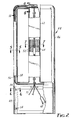
- FIG. 1 shows a partially broken away perspective view of a magnetic electronic article surveillance (EAS) interrogator according to a preferred embodiment of the present invention.
- EAS magnetic electronic article surveillance
- an interrogator 10 comprises two universal lattice assemblies 12 and 14, which are identical to each other, and within which may be installed specific electronic sub-assemblies such that each of the lattice assemblies ultimately performs different functions.
- Each of the universal lattice assemblies 12 and 14 comprises a composite assembly consisting of a frame 16 or 16′, a chassis 18 or 18′, and a coil assembly 20 or 20′.
- the assembly 12 nominally designated as being an amplifier lattice assembly, has installed within the chassis 18 an amplifier panel assembly 22.
- Such an assembly contains appropriate circuits to energize the drive coil 24 within the lattice 12 and via a cable within the raceway 26, the drive coil 24′ within the lattice assembly 14, and appropriate peripheral components such as cooling fans, transformers, etc.
- the lattice assembly 14 may be designated as a processor lattice assembly and therefore fitted with a processor panel assembly 28, which assembly typically includes a processor circuit and peripherals such as an audible alarm 30, diagnostic displays, a photocell, etc. and controls for an indicator light 32 located at the top of the assembly.
- a panel will then be coupled to the sense coil 34′ and via a cable within the raceway 26 to the sense coil 34 within the lattice 12.
- covers 36 Each of the panels are subsequently enclosed by covers 36.
- the respective lattice assemblies 12 and 14 are mounted via a base member 38 to a respective floor surface.
- Such a base unit 38 typically includes a centrally positioned portion 40 with electrical knockouts to provide access for incoming electrical power leads, and projections 42 contacting the floor surface, enabling the base to be mounted on a variety of floor coverings, carpets, tile and the like.
- Each assembly is bolted to a respective base unit through rubber pads 43. Depending upon the extent to which the pads are compressed, the lattice assemblies may be vertically aligned.
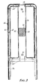
- each of the universal lattice assemblies 44 includes a frame 46, a chassis 48, and a coil assembly 50.
- the chassis 48 is preferably made of welded aluminum channels having a U-shaped cross-section, open on the interior to receive the respective electronic sub-assemblies.
- the chassis 48 has an open portion 51 in the top section to enable air received through vents 52 in the frame 46 in response to a fan, not shown, located within the amplifier panel assembly 22 within the frame 16 of Figure 1.
- the chassis 48 is rigidly mounted within the frame 46 by means of the mounting bosses 54 located at various points around the chassis.
- the coil assembly 50 may also be seen in Figure 2 to comprise respective drive and sense coils 56 and 58.
- the drive coil 56 is an O-configuration extending around the outer arms of the frame and terminating in leads 60.
- the sense coil 58 has a generally figure-8 configuration and extends both around the outer arms as well as through the center or vertical portion 62 of the frame. Also positioned within that center portion 62 is a null adjustment mechanism 64 within which the sense coil is positioned.
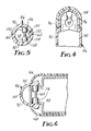
- each of the frame 46 is constructed of two identical half-shells, one of which 66, is shown in Figure 3.
- the half-shell 66 includes an interior cavity which extends uninterruptedly through the upper halves of both outer legs and the interior vertical section.
- the coil assembly is firmly positioned alongside the mounting bosses 68 at numerous locations throughout the half-shell 66.
- the center vertical section includes mounting bosses 70 and 72 onto which may be mounted the coil support 110 as seen in more detail in Figures 8 and 9.
- the half-shell also includes an upper portion 74 over which may be mounted a respective cover, not shown, which may also include an indicator light as appropriate.
- the center vertical portion 76 is further provided with a vent 78 to allow clean air to be admitted therethrough and be drawn downward through an access hole in the chassis for cooling electronic componentry located in the lower portion of the assembly.
- mounting bushings 80 and 82 within which the nulling apparatus may be positioned.
- the respective edges of the center portion have alternating male and female mortices to prevent the half-shells from shifting during assembly.
- the frame 46 includes appropriate mounting bosses 84 and flanges 86 for receiving and mounting the chassis shown as element 48 in Figure 2.
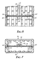
- each frame 46 comprises two half-shells 90 and 92 and a cover 94 secured to the respective half-shells by means of screws 96.
- the coil assembly which would normally occupy the space 98 has been omitted.
- the frame 90 is further shown in the cross-sectional view of Figure 5, and as may there be seen, the half-shell 90 is constructed with exterior flanges adapted to mate with the interior flanges 152 of the half-shell 92.
- the respective halves are further shown to be assembled with a barbed pin 154 inserted into each of the respective bosses 156 and 158.
- reveal lines 160 and 162 are formed to obscure any irregularities which may otherwise be formed in the seam, thereby improving the aesthetic appearance of the ultimate assembly.
- the coil assembly has also been omitted for purposes of clarity, but would normally be placed within the cavity 98 and securely positioned therein via webs extending to the bosses 156 and 158.
- FIG. 6 A still further cross-sectional view of the assembly shown in Figure 2 is taken along the line 6-6 as shown in Figure 6.
- the frame 46 formed of the two identical half-shells 90 and 92, is assembled so as to enclose the chassis 48 via the bosses 54 which enter through matching holes to accurately index the chassis.
- the half-shells 90 and 92 are then held in place via a barbed pin 164.
- the respective flanges meet on an internal surface to leave a reveal line 160, which obscures the actual seam and improves the aesthetics of the overall assembly.
- FIG. 7 a cross-sectional view of the lattice assembly shown in Figure 2 taken along the line 7-7 is shown in Figure 7.
- the center vertical portions of the frame made of the identical half-shells 90 and 92, have mating flanges so as to leave the reveal line 160 extending along both edges, and have on the inside edge molded bushings 170 within which may be positioned restraining collars 172 which in turn support the threaded shaft 174 of the null adjustment mechanism.
- This shaft has a turned down portion inboard of each of the collars 172 to prevent lateral motion of the shaft 174.
- the shaft 174 is further adapted with a screwdriver slot or the like to which access is provided through a mating hole in the frame to enable rotation of the shaft 174.
- null adjustment mechanism includes a U-shaped screw follower member 176, one edge of which is threaded to the shaft 174. Within the member 176 is positioned a channel member 178 each end of which is secured within mounting bosses at the upper and lower portions of the center vertical portions of the frame. The sense coil 180 is positioned within and supported by the member 178..
- the mechanism 100 preferably includes a threaded shaft 102, which functions as a lead screw, an adjusting bracket 104 which functions as a screw follower, and restraining collars 106 and 108.
- the collars are mounted in the mounting bushings 80 and 82 as shown in Figure 3.
- the adjusting bracket 104 is positioned to receive the coil support 110 which is securely strapped to the cable assembly 112, and forces controlled movement of the sense coil as the bracket is displaced.
- the bracket 104 is threaded on one end 114, such that as the threaded shaft 102 is rotated, the bracket moves horizontally to reposition the sense coil.
- the sense coil is terminated in a two conductor cable, and that cable is in turn connected to a five conductor cable which makes up the sense coil.
- the sense coil thus consists of five turns, as each successive conductor within the five conductor cable is offset upon making one complete loop through the assembly to a successive conductor in the cable, the fifth conductor then being connected to the other terminal of the two conductor input cable.
- the coil assembly 122 comprises a figure-O drive coil 124 and a figure-8 sense coil 126.
- the drive coil 124 terminates at the leads 128, and extends around the outer periphery of the entire coil assembly.
- the sense coil 126 is terminated via the two conductor cable 130 and extends around the outer periphery of the assembly, while the center, crossover portions 131 of the sense coil 126 are securely positioned within a plastic extrusion 110, forming the support member to facilitate positioning the coil via the null adjustment mechanism as previously described.
- the entire coil assembly 122 is held together via windings of electrical tape and nylon cable wraps in a typical manner.
- the drive coil is preferably constructed of a number 8 AWG cable having 37 strands of 24 gauge wire individually insulated wire therein in a "Litz" construction, thereby providing consistent high and uniform impedance.
- the lattice assembly of the present invention is particularly desirably provided and inventoried without the specific electronic sub-assemblies and covers in place, thereby decreasing the number of components which must be separately stocked.
- the requisite electronic sub-assemblies Upon receipt of an order for a particular EAS system configuration, whether it be for a one or two, etc. interrogation zone system, the requisite electronic sub-assemblies will be installed in the lattice assemblies and the covers put in place. The completed system is then in condition for shipping to a customer for installation.
- one half-shell of the frame is desirably inserted into a fixture to prevent undue movement.
- the chassis is positioned onto the mounting bosses within the frame to cause it to be rigidly indexed in place, and the wiring harness is similarly positioned about the positioning bosses within the upper part of the half-shell.
- Barbed pins are inserted into mating bosses and epoxy adhesive is then desirably positioned along all mating surfaces of the housing.
- the opposite half-shell is then positioned and snapped into place, thereby providing a rigid composite assembly, which upon installation is firmly positioned in place so as to prevent accidental displacement and need for service adjustment.
Landscapes
- Engineering & Computer Science (AREA)
- Physics & Mathematics (AREA)
- Structural Engineering (AREA)
- Signal Processing (AREA)
- Automation & Control Theory (AREA)
- Computer Security & Cryptography (AREA)
- Electromagnetism (AREA)
- General Physics & Mathematics (AREA)
- Architecture (AREA)
- Civil Engineering (AREA)
- Burglar Alarm Systems (AREA)
- Geophysics And Detection Of Objects (AREA)
Applications Claiming Priority (2)
| Application Number | Priority Date | Filing Date | Title |
|---|---|---|---|
| US437074 | 1989-11-15 | ||
| US07/437,074 US4994939A (en) | 1989-11-15 | 1989-11-15 | Universal lattice for magnetic-electronic article surveillance system |
Publications (3)
| Publication Number | Publication Date |
|---|---|
| EP0428384A2 true EP0428384A2 (fr) | 1991-05-22 |
| EP0428384A3 EP0428384A3 (en) | 1992-04-22 |
| EP0428384B1 EP0428384B1 (fr) | 1995-05-03 |
Family
ID=23734954
Family Applications (1)
| Application Number | Title | Priority Date | Filing Date |
|---|---|---|---|
| EP90312381A Expired - Lifetime EP0428384B1 (fr) | 1989-11-15 | 1990-11-13 | Réseau universel pour système magnétique-électronique de surveillance d'articles |
Country Status (8)
| Country | Link |
|---|---|
| US (1) | US4994939A (fr) |
| EP (1) | EP0428384B1 (fr) |
| JP (1) | JPH03185597A (fr) |
| KR (1) | KR910010035A (fr) |
| AU (1) | AU625143B2 (fr) |
| CA (1) | CA2026976A1 (fr) |
| DE (1) | DE69019106T2 (fr) |
| ES (1) | ES2071787T3 (fr) |
Cited By (4)
| Publication number | Priority date | Publication date | Assignee | Title |
|---|---|---|---|---|
| EP0629019A1 (fr) * | 1993-06-11 | 1994-12-14 | Actron Entwicklungs AG | Dispositif d'antenne pour systèmes électroniques de protection d'objects contre le vol |
| EP0703637A1 (fr) * | 1994-09-23 | 1996-03-27 | Actron Entwicklungs AG | Antenne pour un système électronique de surveillance |
| EP0726549A3 (fr) * | 1995-02-07 | 1996-11-06 | Esselte Meto Int Gmbh | Dispositif de détection d'un article pourvu d'un élément de sécurité éléctronique |
| DE19726986A1 (de) * | 1997-06-25 | 1999-01-07 | Meto International Gmbh | Vorrichtung zur Überwachung von elektronischen gesicherten Artikeln in einer Überwachungszone |
Families Citing this family (12)
| Publication number | Priority date | Publication date | Assignee | Title |
|---|---|---|---|---|
| USD336259S (en) | 1990-02-14 | 1993-06-08 | Ateliers Reunis Caddie | Electronic gate |
| US5315289A (en) * | 1991-09-16 | 1994-05-24 | Fuller Terry A | Anticipatory interactive protective system |
| US5440296A (en) * | 1993-04-29 | 1995-08-08 | Minnesota Mining And Manufacturing Company | Coil assembly for electronic article surveillance system |
| US5349502A (en) * | 1993-04-29 | 1994-09-20 | Minnesota Mining And Manufacturing Company | Universal lattice for magnetic electronic article surveillance system |
| US5627516A (en) * | 1994-09-28 | 1997-05-06 | Sensormatic Electronics Corporation | Electronic article surveillance input configuration control system employing expert system techniques for dynamic optimization |
| JP3389464B2 (ja) | 1997-08-07 | 2003-03-24 | 三洋電機株式会社 | 盗難防止ゲート |
| US6061552A (en) * | 1998-04-28 | 2000-05-09 | Sensormatic Electronics Corporation | EAS pedestal and method for making the same |
| CN100588128C (zh) * | 2001-05-04 | 2010-02-03 | Nxp股份有限公司 | 用于与固定数据载体通信的具有线圈配置的通信设备 |
| US20110148636A1 (en) * | 2009-12-17 | 2011-06-23 | 3M Innovative Properties Company | Detection system |
| US8497776B2 (en) * | 2010-12-29 | 2013-07-30 | Symbol Technologies, Inc. | Radio frequency identification system and method used to perform electronic article surveillance |
| JP2012202967A (ja) | 2011-03-28 | 2012-10-22 | Fuji Xerox Co Ltd | 用紙識別装置、画像読取システム、用紙寸断システム及びプログラム |
| CN117800255B (zh) * | 2024-03-01 | 2024-05-14 | 浙江华视智检科技有限公司 | 一种搬运设备及安检门的安装方法 |
Family Cites Families (4)
| Publication number | Priority date | Publication date | Assignee | Title |
|---|---|---|---|---|
| US4135183A (en) * | 1977-05-24 | 1979-01-16 | Minnesota Mining And Manufacturing Company | Antipilferage system utilizing "figure-8" shaped field producing and detector coils |
| US4509039A (en) * | 1983-07-05 | 1985-04-02 | Minnesota Mining And Manufacturing Company | Shielded, closely spaced transmit-receiver antennas for electronic article surveillance system |
| USD291976S (en) | 1984-12-24 | 1987-09-22 | Minnesota Mining And Manufacturing Company | Antenna housing for an electronic article surveillance system |
| US4677799A (en) * | 1985-12-03 | 1987-07-07 | Minnesota Mining And Manufacturing Company | Multi-sectional raceway |
-
1989
- 1989-11-15 US US07/437,074 patent/US4994939A/en not_active Expired - Fee Related
-
1990
- 1990-10-04 AU AU63797/90A patent/AU625143B2/en not_active Ceased
- 1990-10-04 CA CA002026976A patent/CA2026976A1/fr not_active Abandoned
- 1990-11-13 EP EP90312381A patent/EP0428384B1/fr not_active Expired - Lifetime
- 1990-11-13 DE DE69019106T patent/DE69019106T2/de not_active Expired - Fee Related
- 1990-11-13 ES ES90312381T patent/ES2071787T3/es not_active Expired - Lifetime
- 1990-11-14 JP JP2308460A patent/JPH03185597A/ja active Pending
- 1990-11-14 KR KR1019900018436A patent/KR910010035A/ko not_active Withdrawn
Cited By (6)
| Publication number | Priority date | Publication date | Assignee | Title |
|---|---|---|---|---|
| EP0629019A1 (fr) * | 1993-06-11 | 1994-12-14 | Actron Entwicklungs AG | Dispositif d'antenne pour systèmes électroniques de protection d'objects contre le vol |
| US5585811A (en) * | 1993-06-11 | 1996-12-17 | Actron Enwicklungs Ag | Antenna device for electronic product anti-theft systems |
| EP0703637A1 (fr) * | 1994-09-23 | 1996-03-27 | Actron Entwicklungs AG | Antenne pour un système électronique de surveillance |
| EP0726549A3 (fr) * | 1995-02-07 | 1996-11-06 | Esselte Meto Int Gmbh | Dispositif de détection d'un article pourvu d'un élément de sécurité éléctronique |
| DE19726986A1 (de) * | 1997-06-25 | 1999-01-07 | Meto International Gmbh | Vorrichtung zur Überwachung von elektronischen gesicherten Artikeln in einer Überwachungszone |
| US6181247B1 (en) | 1997-06-25 | 2001-01-30 | Meto International Gmbh | Device for surveying electronically protected items in a monitored area |
Also Published As
| Publication number | Publication date |
|---|---|
| EP0428384A3 (en) | 1992-04-22 |
| JPH03185597A (ja) | 1991-08-13 |
| EP0428384B1 (fr) | 1995-05-03 |
| DE69019106D1 (de) | 1995-06-08 |
| DE69019106T2 (de) | 1995-11-30 |
| AU625143B2 (en) | 1992-07-02 |
| AU6379790A (en) | 1991-05-23 |
| KR910010035A (ko) | 1991-06-28 |
| CA2026976A1 (fr) | 1991-05-16 |
| ES2071787T3 (es) | 1995-07-01 |
| US4994939A (en) | 1991-02-19 |
Similar Documents
| Publication | Publication Date | Title |
|---|---|---|
| EP0428384B1 (fr) | Réseau universel pour système magnétique-électronique de surveillance d'articles | |
| EP0622766B1 (fr) | Antenne en forme d'un treillis pour un système électronique de surveillance d'objets | |
| US5061941A (en) | Composite antenna for electronic article surveillance systems | |
| US5459451A (en) | Electronic article surveillance system with enhanced geometric arrangement | |
| CA2658885C (fr) | Porte avec antenne integree | |
| CA2276412C (fr) | Antenne a boucles multiples | |
| US5877728A (en) | Multiple loop antenna | |
| US9312598B1 (en) | Combined floor mat and antennas for an electronic article surveillance system | |
| JPS6015794A (ja) | アンテナ装置 | |
| JP2001526480A (ja) | Eamシステムのためのアンテナと送信機の配置 | |
| JPH08507660A (ja) | 斜交部材を有する送受アンテナ | |
| US6061552A (en) | EAS pedestal and method for making the same | |
| US5349502A (en) | Universal lattice for magnetic electronic article surveillance system | |
| CN1123089C (zh) | 多环路天线以及使用其的电子物品监视系统 | |
| JP3098163B2 (ja) | 盗難防止装置用アンテナゲート | |
| WO2023082006A1 (fr) | Socle de surveillance électronique d'articles à ossature extrudée |
Legal Events
| Date | Code | Title | Description |
|---|---|---|---|
| PUAI | Public reference made under article 153(3) epc to a published international application that has entered the european phase |
Free format text: ORIGINAL CODE: 0009012 |
|
| 17P | Request for examination filed |
Effective date: 19901207 |
|
| AK | Designated contracting states |
Kind code of ref document: A2 Designated state(s): BE DE ES FR GB IT NL SE |
|
| PUAL | Search report despatched |
Free format text: ORIGINAL CODE: 0009013 |
|
| AK | Designated contracting states |
Kind code of ref document: A3 Designated state(s): BE DE ES FR GB IT NL SE |
|
| 17Q | First examination report despatched |
Effective date: 19940913 |
|
| GRAA | (expected) grant |
Free format text: ORIGINAL CODE: 0009210 |
|
| ITF | It: translation for a ep patent filed | ||
| AK | Designated contracting states |
Kind code of ref document: B1 Designated state(s): BE DE ES FR GB IT NL SE |
|
| REF | Corresponds to: |
Ref document number: 69019106 Country of ref document: DE Date of ref document: 19950608 |
|
| REG | Reference to a national code |
Ref country code: ES Ref legal event code: FG2A Ref document number: 2071787 Country of ref document: ES Kind code of ref document: T3 |
|
| ET | Fr: translation filed | ||
| PLBE | No opposition filed within time limit |
Free format text: ORIGINAL CODE: 0009261 |
|
| STAA | Information on the status of an ep patent application or granted ep patent |
Free format text: STATUS: NO OPPOSITION FILED WITHIN TIME LIMIT |
|
| 26N | No opposition filed | ||
| PGFP | Annual fee paid to national office [announced via postgrant information from national office to epo] |
Ref country code: SE Payment date: 19961022 Year of fee payment: 7 |
|
| PGFP | Annual fee paid to national office [announced via postgrant information from national office to epo] |
Ref country code: NL Payment date: 19961024 Year of fee payment: 7 |
|
| PGFP | Annual fee paid to national office [announced via postgrant information from national office to epo] |
Ref country code: DE Payment date: 19961028 Year of fee payment: 7 |
|
| PGFP | Annual fee paid to national office [announced via postgrant information from national office to epo] |
Ref country code: BE Payment date: 19961029 Year of fee payment: 7 |
|
| PGFP | Annual fee paid to national office [announced via postgrant information from national office to epo] |
Ref country code: FR Payment date: 19971021 Year of fee payment: 8 |
|
| PGFP | Annual fee paid to national office [announced via postgrant information from national office to epo] |
Ref country code: GB Payment date: 19971027 Year of fee payment: 8 |
|
| PGFP | Annual fee paid to national office [announced via postgrant information from national office to epo] |
Ref country code: ES Payment date: 19971113 Year of fee payment: 8 |
|
| PG25 | Lapsed in a contracting state [announced via postgrant information from national office to epo] |
Ref country code: SE Free format text: LAPSE BECAUSE OF NON-PAYMENT OF DUE FEES Effective date: 19971114 |
|
| PG25 | Lapsed in a contracting state [announced via postgrant information from national office to epo] |
Ref country code: BE Free format text: LAPSE BECAUSE OF NON-PAYMENT OF DUE FEES Effective date: 19971130 |
|
| BERE | Be: lapsed |
Owner name: MINNESOTA MINING AND MFG CY Effective date: 19971130 |
|
| PG25 | Lapsed in a contracting state [announced via postgrant information from national office to epo] |
Ref country code: NL Free format text: LAPSE BECAUSE OF NON-PAYMENT OF DUE FEES Effective date: 19980601 |
|
| PG25 | Lapsed in a contracting state [announced via postgrant information from national office to epo] |
Ref country code: DE Free format text: LAPSE BECAUSE OF NON-PAYMENT OF DUE FEES Effective date: 19980801 |
|
| EUG | Se: european patent has lapsed |
Ref document number: 90312381.8 |
|
| NLV4 | Nl: lapsed or anulled due to non-payment of the annual fee |
Effective date: 19980601 |
|
| PG25 | Lapsed in a contracting state [announced via postgrant information from national office to epo] |
Ref country code: GB Free format text: LAPSE BECAUSE OF NON-PAYMENT OF DUE FEES Effective date: 19981113 |
|
| PG25 | Lapsed in a contracting state [announced via postgrant information from national office to epo] |
Ref country code: ES Free format text: LAPSE BECAUSE OF NON-PAYMENT OF DUE FEES Effective date: 19981114 |
|
| GBPC | Gb: european patent ceased through non-payment of renewal fee |
Effective date: 19981113 |
|
| PG25 | Lapsed in a contracting state [announced via postgrant information from national office to epo] |
Ref country code: FR Free format text: LAPSE BECAUSE OF NON-PAYMENT OF DUE FEES Effective date: 19990730 |
|
| REG | Reference to a national code |
Ref country code: FR Ref legal event code: ST |
|
| REG | Reference to a national code |
Ref country code: ES Ref legal event code: FD2A Effective date: 19991214 |
|
| PG25 | Lapsed in a contracting state [announced via postgrant information from national office to epo] |
Ref country code: IT Free format text: LAPSE BECAUSE OF NON-PAYMENT OF DUE FEES;WARNING: LAPSES OF ITALIAN PATENTS WITH EFFECTIVE DATE BEFORE 2007 MAY HAVE OCCURRED AT ANY TIME BEFORE 2007. THE CORRECT EFFECTIVE DATE MAY BE DIFFERENT FROM THE ONE RECORDED. Effective date: 20051113 |