EP0428408A2 - Automatische Kalibrierung eines Vorlagenleseapparats - Google Patents
Automatische Kalibrierung eines Vorlagenleseapparats Download PDFInfo
- Publication number
- EP0428408A2 EP0428408A2 EP90312444A EP90312444A EP0428408A2 EP 0428408 A2 EP0428408 A2 EP 0428408A2 EP 90312444 A EP90312444 A EP 90312444A EP 90312444 A EP90312444 A EP 90312444A EP 0428408 A2 EP0428408 A2 EP 0428408A2
- Authority
- EP
- European Patent Office
- Prior art keywords
- document
- read
- reading
- calibration
- start time
- Prior art date
- Legal status (The legal status is an assumption and is not a legal conclusion. Google has not performed a legal analysis and makes no representation as to the accuracy of the status listed.)
- Granted
Links
Images


Classifications
-
- H—ELECTRICITY
- H04—ELECTRIC COMMUNICATION TECHNIQUE
- H04N—PICTORIAL COMMUNICATION, e.g. TELEVISION
- H04N1/00—Scanning, transmission or reproduction of documents or the like, e.g. facsimile transmission; Details thereof
-
- H—ELECTRICITY
- H04—ELECTRIC COMMUNICATION TECHNIQUE
- H04N—PICTORIAL COMMUNICATION, e.g. TELEVISION
- H04N1/00—Scanning, transmission or reproduction of documents or the like, e.g. facsimile transmission; Details thereof
- H04N1/04—Scanning arrangements, i.e. arrangements for the displacement of active reading or reproducing elements relative to the original or reproducing medium, or vice versa
- H04N1/047—Detection, control or error compensation of scanning velocity or position
- H04N1/0473—Detection, control or error compensation of scanning velocity or position in subscanning direction, e.g. picture start or line-to-line synchronisation
-
- H—ELECTRICITY
- H04—ELECTRIC COMMUNICATION TECHNIQUE
- H04N—PICTORIAL COMMUNICATION, e.g. TELEVISION
- H04N1/00—Scanning, transmission or reproduction of documents or the like, e.g. facsimile transmission; Details thereof
- H04N1/04—Scanning arrangements, i.e. arrangements for the displacement of active reading or reproducing elements relative to the original or reproducing medium, or vice versa
- H04N1/12—Scanning arrangements, i.e. arrangements for the displacement of active reading or reproducing elements relative to the original or reproducing medium, or vice versa using the sheet-feed movement or the medium-advance or the drum-rotation movement as the slow scanning component, e.g. arrangements for the main-scanning
-
- H—ELECTRICITY
- H04—ELECTRIC COMMUNICATION TECHNIQUE
- H04N—PICTORIAL COMMUNICATION, e.g. TELEVISION
- H04N1/00—Scanning, transmission or reproduction of documents or the like, e.g. facsimile transmission; Details thereof
- H04N1/04—Scanning arrangements, i.e. arrangements for the displacement of active reading or reproducing elements relative to the original or reproducing medium, or vice versa
- H04N1/19—Scanning arrangements, i.e. arrangements for the displacement of active reading or reproducing elements relative to the original or reproducing medium, or vice versa using multi-element arrays
- H04N1/191—Scanning arrangements, i.e. arrangements for the displacement of active reading or reproducing elements relative to the original or reproducing medium, or vice versa using multi-element arrays the array comprising a one-dimensional [1D] array
- H04N1/192—Simultaneously or substantially simultaneously scanning picture elements on one main scanning line
- H04N1/193—Simultaneously or substantially simultaneously scanning picture elements on one main scanning line using electrically scanned linear arrays, e.g. linear CCD arrays
-
- H—ELECTRICITY
- H04—ELECTRIC COMMUNICATION TECHNIQUE
- H04N—PICTORIAL COMMUNICATION, e.g. TELEVISION
- H04N2201/00—Indexing scheme relating to scanning, transmission or reproduction of documents or the like, and to details thereof
- H04N2201/04—Scanning arrangements
- H04N2201/047—Detection, control or error compensation of scanning velocity or position
- H04N2201/04701—Detection of scanning velocity or position
- H04N2201/0471—Detection of scanning velocity or position using dedicated detectors
-
- H—ELECTRICITY
- H04—ELECTRIC COMMUNICATION TECHNIQUE
- H04N—PICTORIAL COMMUNICATION, e.g. TELEVISION
- H04N2201/00—Indexing scheme relating to scanning, transmission or reproduction of documents or the like, and to details thereof
- H04N2201/04—Scanning arrangements
- H04N2201/047—Detection, control or error compensation of scanning velocity or position
- H04N2201/04701—Detection of scanning velocity or position
- H04N2201/04715—Detection of scanning velocity or position by detecting marks or the like, e.g. slits
- H04N2201/04717—Detection of scanning velocity or position by detecting marks or the like, e.g. slits on the scanned sheet, e.g. a reference sheet
-
- H—ELECTRICITY
- H04—ELECTRIC COMMUNICATION TECHNIQUE
- H04N—PICTORIAL COMMUNICATION, e.g. TELEVISION
- H04N2201/00—Indexing scheme relating to scanning, transmission or reproduction of documents or the like, and to details thereof
- H04N2201/04—Scanning arrangements
- H04N2201/047—Detection, control or error compensation of scanning velocity or position
- H04N2201/04701—Detection of scanning velocity or position
- H04N2201/04732—Detecting at infrequent intervals, e.g. once or twice per line for main-scan control
-
- H—ELECTRICITY
- H04—ELECTRIC COMMUNICATION TECHNIQUE
- H04N—PICTORIAL COMMUNICATION, e.g. TELEVISION
- H04N2201/00—Indexing scheme relating to scanning, transmission or reproduction of documents or the like, and to details thereof
- H04N2201/04—Scanning arrangements
- H04N2201/047—Detection, control or error compensation of scanning velocity or position
- H04N2201/04701—Detection of scanning velocity or position
- H04N2201/04737—Detection of scanning velocity or position by detecting the scanned medium directly, e.g. a leading edge
-
- H—ELECTRICITY
- H04—ELECTRIC COMMUNICATION TECHNIQUE
- H04N—PICTORIAL COMMUNICATION, e.g. TELEVISION
- H04N2201/00—Indexing scheme relating to scanning, transmission or reproduction of documents or the like, and to details thereof
- H04N2201/04—Scanning arrangements
- H04N2201/047—Detection, control or error compensation of scanning velocity or position
- H04N2201/04753—Control or error compensation of scanning position or velocity
- H04N2201/04758—Control or error compensation of scanning position or velocity by controlling the position of the scanned image area
- H04N2201/04767—Control or error compensation of scanning position or velocity by controlling the position of the scanned image area by controlling the timing of the signals, e.g. by controlling the frequency o phase of the pixel clock
- H04N2201/04781—Controlling the phase of the signals
- H04N2201/04786—Controlling a start time, e.g. for output of a line of data
-
- H—ELECTRICITY
- H04—ELECTRIC COMMUNICATION TECHNIQUE
- H04N—PICTORIAL COMMUNICATION, e.g. TELEVISION
- H04N2201/00—Indexing scheme relating to scanning, transmission or reproduction of documents or the like, and to details thereof
- H04N2201/04—Scanning arrangements
- H04N2201/047—Detection, control or error compensation of scanning velocity or position
- H04N2201/04753—Control or error compensation of scanning position or velocity
- H04N2201/04793—Control or error compensation of scanning position or velocity using stored control or compensation data, e.g. previously measured data
Definitions
- the present invention relates to automatic calibration of document reading apparatus, and in particular to a method and apparatus for use, for example in facsimile or copying equipment, to adjust a read start position of a document to be read.
- Facsimile and copy machines are widely used in various fields.
- the document is automatically transported by feeding means from an insertion portion of the device and is read by an optical read means mounted therein.
- the optical read means is constituted by some basic structural elements, i.e. a light source for irradiating the document, a reflection mirror for receiving a reflected light from the document, a collection lens for collecting the reflected light, and a CCD (charge coupled device) for converting the reflected light to an electrical signal.
- a light source for irradiating the document
- a reflection mirror for receiving a reflected light from the document
- a collection lens for collecting the reflected light
- CCD charge coupled device
- Embodiments of first and second aspects of the present invention can provide an apparatus and a method, respectively, for automatically adjusting a read start position of a document to be read.
- An embodiment of a first aspect of the present invention can provide an apparatus for adjusting the read start position of a document to be read, the apparatus including: a read unit having at least a transportation element for transporting the document to be read, a detection switch for detecting a top of the document, and an optical read unit for reading the document; and a control unit having a memory for storing a reference read start time and a corrected read start time, a timer for counting the reference read start time, and a correction unit for correcting the reference read start time; wherein the control unit corrects the reference read start time in such a way that, in a read position adjusting mode set prior to an actual read operation of the document, a test chart is inserted into the transportation element, an actual read line provided on the test chart is detected and an error between the actual read line and a reference read line provided on the test chart is obtained, a time lag is calculated from the above error and the reference read start time is corrected based on the time lag.
- the test chart has a cut portion provided at the center of the top of the test chart, the cut portion having a bottom reference line, and two slanted reference lines each having a predetermined angle from the top of the cut portion, the two slanted reference lines being colored black.
- An embodiment of a second aspect of the present invention can provide a method for adjusting the read start position of a document to be read; the document being inserted into a read unit having at least a transportation element for transporting the document to be read, a detection switch for detecting the top of the document, and an optical read unit for reading the document; and a read operation for the document being controlled by a control unit having a memory for storing a reference read start time and a corrected read start time, a timer for counting the reference read start time, and a correction unit for correcting the reference read start time; the method including: setting a read position adjusting mode in a manufacturing process prior to an actual read operation of the document, inserting a test chart into the transportation element, detecting cross points between an actual read line and a reference read line each provided on the test chart, and obtaining an error between these lines, calculating a time lag from the above error and correcting the reference read start time based on the time lag, and storing the corrected read start time in the memory, the
- Figures 1 and 2 are views for explaining mechanical installation errors in an optical read means.
- reference number 11 denotes a CCD (charge coupled device) for converting a reflected light to an electrical signal
- 12 a collection lens for collecting the reflected light
- 13 a reflection mirror for changing a light path to the collection lens
- 14 a light source for irradiating a document 15.
- CCD charge coupled device
- the document to be read is transported in a direction shown by an arrow, this transportation direction of the document 15 being called a sub-scanning direction.
- the light source 14 irradiates the document 15, the light reflected from the document 15 is collected by the collection lens 12 through the reflection mirror 13, and the collected light is received by the CCD 11.
- the CCD 11 converts the reflected light to an electrical signal in a main-scanning direction, i.e., transversely to the transportation direction of the document 15.
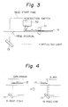
- Figure 3 shows a schematic view of parks of a document reader.
- reference number 31 denotes a document transportation element, and 32 a document detection switch.
- the detection switch 32 detects the end of the document 15.
- the read operation of the document 15 is started after the elapse of a predetermined time just after the detection of the document 15 by the detection element 32. That is, the time is counted after detection of the document 15, and the read operation is started after an elapse of the predetermined time.
- the read start time is fixedly defined based on the amount of movement of the document 15 just after the detection by the switch 32.
- the read start position is defined by a fixed time.
- Figure 4 is a view for explaining problems in the document reader shown in Fig. 3.
- the mechanical installation error shown in Figs. 1 and 2 occurs in the CCD 11 and the reflection mirror 13
- a data error occurs causing the top of the document not to be read, and a blank portion at the bottom of the document occurs at the end of the read operation.
- the installation positions of the CCD 11 and the reflection mirror 13 can be adjusted in the manufacturing process with a view to obtaining a correct normal read position.
- Figure 5 is a schematic block diagram of an apparatus for adjusting a read start position according to the present invention.
- the apparatus is constituted by a read unit 1 and a control unit 2.
- the mechanical structure of the read unit 1 is the same as the Figure 3 document reader i.e. the read unit 1 is constituted by the CCD 11, the collection lens 12, the reflection mirror 13, the light source 14, the document transportation element 31 and the document detection switch 32.
- the read start time for the document is variable and is corrected by using a test chart in the read position adjusting mode prior to the actual read operation. That is, the read position adjusting mode is set in the manufacturing process or in a maintenance process of the apparatus to correct the reference read start time. In this case, the read start time is adjusted based on an error between an actual read line and a reference read line of the test chart. Accordingly, it is possible to easily coincide the read start position with the top of the document without fine mechanical adjustment of the CCD 11 and the reflection mirror 13 as explained in detail hereinafter.
- control unit 2 is constituted by a microprocessor including a storage unit (memory) 21, a time counting unit (timer) 22 and a correction unit 23.
- the memory 21 stores a control program for adjusting the read start position and correcting the read start time. Further, the memory 21 stores a reference read start time and a corrected read start time as explained in detail hereinafter.
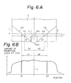
- Figure 6A is a view for explaining a test chart for use with an embodiment of the present invention
- Figure 6B is a graph illustrating the relationship between an amount of received light and a position on the CCD.
- the test chart C is inserted to the transportation element 31 in the direction of the arrow.
- the test chart comprises a cut portion (1) in the center of the test chart C and the cut portion (1) has a rearward reference line (4).
- the test chart comprises two slanted reference lines (3) each having an angle ⁇ from forward points (2). These lines (3) are colored black.
- the rearward reference line (4) of the cut portion (1) is used as the reference read line and is detected by the detection switch 32. Accordingly, the rearward reference line (4) corresponds to the leading edge of the document 15.
- the slanted reference lines (3) are used for calculating the time of the error between rearward reference line (4) and the actual read line.
- the ordinate denotes the amount of the received light at the CCD and the abscissa denotes the position on the CCD.
- the amount of light received by the CCD is considerably reduced at the positions labelled X1 and X2 because the reference read line is black so that the reflected light is reduced.
- a pattern of Fig. 6B is displayed on a CRT, it is possible to detect distances a1 and a2 from a center line L of the CCD.
- the difference between a1 and b1 and the difference between a2 and b2 represent the error E between the actual read line X and the rearward reference line (4). Further, it is possible to detect a slanting of the document based on the difference between the distances a1 and a2.
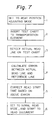
- FIG. 7 is a basic flowchart illustrating the operation of the control unit 2 shown in Fig. 5.
- the read position adjusting mode is set by an operator sin the manufacturing process (step 1), and the test chart C is inserted into the transportation element 31 (step 2).
- the control unit 2 is constituted by a microprocessor including the memory 21, the timer 22 and the correction unit 23.
- the memory 21 stores a control program for adjusting the read start position and correcting the read start time. Further, the memory 21 stores a reference read start time and a corrected read start time.
- step 3 When the document detection switch 32 detects the bottom reference line (4) of the test chart C (step 3), data regarding the reference read start time is read from the memory 21, and the timer 22 starts to count the reference read start time. When the count of the reference read start time is completed, the control unit 2 starts to read the data from the CCD 11. In this case, the first one line of data is read from the CCD 11 to analyze and correct in the correction unit 23 as follows.
- the correction unit 23 detects the points X1 and X2 each indicating the cross point between the reference line (3) and the actual read line X.
- the correction unit 23 detects the distances a1 and a2 from the center line L.
- T1 (b1 - a1)tan ⁇ ⁇ V (1)
- T2 (b2 - a2)tan ⁇ ⁇ V (2)
- Tc Tref ⁇ (T1 + T2)/2 (3)
- T1 and T2 are time lags
- b1, b2, and ⁇ are fixed values as previously explained
- Tc is the corrected read start time
- Tref is the reference read start time
- V is a transportation speed of the document.
- the memory 21 stores the corrected read time Tc.
- step 6 when the read position adjusting mode is completed, the apparatus is changed to a normal read operation mode to read the document as explained hereinafter. That is, the operation of the control unit 2 at the normal operation mode is explained hereinafter. As explained above, this mode is performed after completion of the read position adjusting mode.
- Fig. 5 when the document 15 is inserted into the transportation element 31, the document 15 is automatically transported and detected by the detection switch 32.
- the detection of the document is input to the control unit 2
- the corrected read start time To is read out from the memory 21, and the timer 22 starts to count the corrected read start time To.
- the corrected read start time Tc is completed, at the same time, the read operation from the CCD 11 is started.
- the read position adjusting mode is selected during the manufacturing process of the apparatus, i.e. before any actual read operation (i.e., normal read operation) of the document.
- the read start time is corrected by using the test chart so as to coincide the top of the document with the read start position at the actual read operation. Accordingly, it is not necessary to precisely adjust the mechanical installation position of the CCD and the reflection mirror.
- Document reading apparatus embodying the present invention can also be applied to a copy machine having the same optical read means as that of the facsimile apparatus described above.
Landscapes
- Engineering & Computer Science (AREA)
- Multimedia (AREA)
- Signal Processing (AREA)
- Facsimile Scanning Arrangements (AREA)
- Facsimiles In General (AREA)
Applications Claiming Priority (2)
| Application Number | Priority Date | Filing Date | Title |
|---|---|---|---|
| JP296707/89 | 1989-11-15 | ||
| JP1296707A JPH03158066A (ja) | 1989-11-15 | 1989-11-15 | 原稿読取位置調整方法 |
Publications (3)
| Publication Number | Publication Date |
|---|---|
| EP0428408A2 true EP0428408A2 (de) | 1991-05-22 |
| EP0428408A3 EP0428408A3 (en) | 1992-05-13 |
| EP0428408B1 EP0428408B1 (de) | 1996-04-24 |
Family
ID=17837045
Family Applications (1)
| Application Number | Title | Priority Date | Filing Date |
|---|---|---|---|
| EP90312444A Expired - Lifetime EP0428408B1 (de) | 1989-11-15 | 1990-11-15 | Automatische Kalibrierung eines Vorlagenleseapparats |
Country Status (5)
| Country | Link |
|---|---|
| US (1) | US5245440A (de) |
| EP (1) | EP0428408B1 (de) |
| JP (1) | JPH03158066A (de) |
| KR (1) | KR940007679B1 (de) |
| DE (1) | DE69026681T2 (de) |
Cited By (5)
| Publication number | Priority date | Publication date | Assignee | Title |
|---|---|---|---|---|
| EP0590533A1 (de) * | 1992-09-25 | 1994-04-06 | Mita Industrial Co. Ltd. | Bilderzeugungsgerät |
| EP0592501A1 (de) * | 1991-07-04 | 1994-04-20 | WOYDICH, Horst | Vorlage zum einscannen von flächig gespeicherten daten |
| EP0735738A3 (de) * | 1995-03-30 | 1999-05-06 | Hewlett-Packard Company | Vorrichtung und Verfahren zur Kalibrierung von einer Faksimileabtastposition |
| US7869091B2 (en) | 2004-02-11 | 2011-01-11 | Hewlett-Packard Development Company, L.P. | Scanner characteristic adjustment |
| EP2541889A3 (de) * | 2011-06-30 | 2013-09-25 | Brother Kogyo Kabushiki Kaisha | Bildlesevorrichtung |
Families Citing this family (14)
| Publication number | Priority date | Publication date | Assignee | Title |
|---|---|---|---|---|
| JP2889080B2 (ja) * | 1993-04-27 | 1999-05-10 | シャープ株式会社 | スキャナ |
| US5646746A (en) * | 1993-10-27 | 1997-07-08 | Nikon Corporation | Image input device having carriage that includes a movable origin detector |
| JPH0865000A (ja) * | 1994-08-24 | 1996-03-08 | Matsushita Electric Ind Co Ltd | プリント基板外観検査装置 |
| US6445813B1 (en) | 1994-08-24 | 2002-09-03 | Matsushita Electric Industrial Co., Ltd. | System for inspecting an apparatus of a printed circuit board |
| TW363326B (en) * | 1997-02-15 | 1999-07-01 | Benq Corp | Initialization positioning method of transparency scanning light source |
| JP3576966B2 (ja) * | 2000-12-07 | 2004-10-13 | キヤノン株式会社 | 画像読取装置及び読取位置設定方法 |
| KR100428547B1 (ko) * | 2002-08-07 | 2004-04-29 | 삼성전자주식회사 | 원고의 선단 감지가 가능한 화상 스캐닝 유니트 및 그 방법 |
| EP1427176B1 (de) * | 2002-11-28 | 2014-05-21 | Océ-Technologies B.V. | Verfahren und Vorrichtung zur Kalibration eines Transportscanners und Testvorlage zur Verwendung mit einem solchen Verfahren und einer solchen Abtastvorrichtung |
| JP4181483B2 (ja) * | 2002-11-28 | 2008-11-12 | オセ−テクノロジーズ ビーブイ | トランスポートスキャナーを較正するための方法及び装置並びに該方法を利用するためのテスト原稿 |
| KR20060055940A (ko) * | 2004-11-19 | 2006-05-24 | 삼성전자주식회사 | 메모리를 포함하는 ccd 및 이를 포함하는 화상입력장치 및 화상입력방법 |
| JP5020738B2 (ja) * | 2007-08-10 | 2012-09-05 | キヤノン株式会社 | 画像読取装置、その制御方法及び制御プログラム |
| JP4827939B2 (ja) * | 2009-02-18 | 2011-11-30 | シャープ株式会社 | 画像読取装置及び画像形成装置並びに画像処理装置 |
| JP4954237B2 (ja) * | 2009-03-30 | 2012-06-13 | シャープ株式会社 | 画像読取装置及び画像形成装置 |
| JP7392463B2 (ja) * | 2019-12-25 | 2023-12-06 | セイコーエプソン株式会社 | 画像読取装置 |
Family Cites Families (11)
| Publication number | Priority date | Publication date | Assignee | Title |
|---|---|---|---|---|
| DE2513042C3 (de) * | 1975-03-25 | 1981-07-30 | Dr.-Ing. Rudolf Hell Gmbh, 2300 Kiel | Verfahren zum ortsgenauen Einstellen des Beginns und Endes der Reproduktion |
| DE2523042A1 (de) * | 1975-05-24 | 1976-12-02 | Reich Maschf Gmbh Karl | Zufuehrvorrichtung fuer umleimer bei kantenanleimmaschinen |
| DE3174899D1 (en) * | 1980-10-31 | 1986-08-07 | Toshiba Kk | Picture information input apparatus |
| JPH0626423B2 (ja) * | 1983-12-08 | 1994-04-06 | キヤノン株式会社 | 原稿読取り装置 |
| JPS60124174A (ja) * | 1983-12-09 | 1985-07-03 | Canon Inc | 原稿読み取り装置 |
| US4605970A (en) * | 1984-10-01 | 1986-08-12 | Tektronix, Inc. | Method and apparatus for calibrating an optical document digitizer |
| JPH0626427B2 (ja) * | 1984-10-16 | 1994-04-06 | キヤノン株式会社 | 画像形成装置 |
| GB8508354D0 (en) * | 1985-03-29 | 1985-05-09 | Rank Cintel Ltd | Microform reading apparatus |
| US4862284A (en) * | 1986-09-16 | 1989-08-29 | Matsushita Electric Industrial Co., Ltd. | Copier with accurately position-controllable sub-scanning unit |
| JPH01115267A (ja) * | 1987-10-29 | 1989-05-08 | Ricoh Co Ltd | 画像読取装置 |
| JPH0648844B2 (ja) * | 1990-04-18 | 1994-06-22 | 大日本スクリーン製造株式会社 | 画像読取装置 |
-
1989
- 1989-11-15 JP JP1296707A patent/JPH03158066A/ja active Pending
-
1990
- 1990-11-15 US US07/613,093 patent/US5245440A/en not_active Expired - Lifetime
- 1990-11-15 DE DE69026681T patent/DE69026681T2/de not_active Expired - Fee Related
- 1990-11-15 KR KR1019900018459A patent/KR940007679B1/ko not_active Expired - Fee Related
- 1990-11-15 EP EP90312444A patent/EP0428408B1/de not_active Expired - Lifetime
Cited By (9)
| Publication number | Priority date | Publication date | Assignee | Title |
|---|---|---|---|---|
| EP0592501A1 (de) * | 1991-07-04 | 1994-04-20 | WOYDICH, Horst | Vorlage zum einscannen von flächig gespeicherten daten |
| EP0590533A1 (de) * | 1992-09-25 | 1994-04-06 | Mita Industrial Co. Ltd. | Bilderzeugungsgerät |
| US5418603A (en) * | 1992-09-25 | 1995-05-23 | Mita Industrial Co., Ltd. | Image forming apparatus capable of evaluating image forming performance |
| EP0735738A3 (de) * | 1995-03-30 | 1999-05-06 | Hewlett-Packard Company | Vorrichtung und Verfahren zur Kalibrierung von einer Faksimileabtastposition |
| US6016207A (en) * | 1995-03-30 | 2000-01-18 | Hewlett-Packard Company | Facsimile scan position calibration apparatus and method |
| US7869091B2 (en) | 2004-02-11 | 2011-01-11 | Hewlett-Packard Development Company, L.P. | Scanner characteristic adjustment |
| EP2541889A3 (de) * | 2011-06-30 | 2013-09-25 | Brother Kogyo Kabushiki Kaisha | Bildlesevorrichtung |
| US8693072B2 (en) | 2011-06-30 | 2014-04-08 | Brother Kogyo Kabushiki Kaisha | Image reading apparatus |
| US9036165B2 (en) | 2011-06-30 | 2015-05-19 | Brother Kogyo Kabushiki Kaisha | Image reading apparatus |
Also Published As
| Publication number | Publication date |
|---|---|
| KR940007679B1 (ko) | 1994-08-22 |
| EP0428408A3 (en) | 1992-05-13 |
| US5245440A (en) | 1993-09-14 |
| JPH03158066A (ja) | 1991-07-08 |
| EP0428408B1 (de) | 1996-04-24 |
| KR910010990A (ko) | 1991-06-29 |
| DE69026681D1 (de) | 1996-05-30 |
| DE69026681T2 (de) | 1996-09-19 |
Similar Documents
| Publication | Publication Date | Title |
|---|---|---|
| EP0428408B1 (de) | Automatische Kalibrierung eines Vorlagenleseapparats | |
| EP0261966B1 (de) | Rastereingangsabtaster | |
| EP0522640B1 (de) | Siebdruckvorrichtung mit kontinuierlicher Positionskontrolle des rotierenden Siebes | |
| CA2077832C (en) | Method and apparatus for image registration in a single pass ros system | |
| US4577095A (en) | Automatic focusing apparatus for a semiconductor pattern inspection system | |
| US4910411A (en) | Apparatus for inspecting a side wall of a tire | |
| US5351834A (en) | Monitoring of printed sheets | |
| US6005243A (en) | Synchronous adjustment method, apparatus, and computer program product in a multiple beam optical system | |
| EP0072568B1 (de) | Verfahren und Apparat zur Feststellung des Vorderrandes eines abzutastenden Blattes | |
| US4764015A (en) | Method and apparatus for non-contact spatial measurement | |
| EP0372209B1 (de) | Längenmessgerät | |
| US4751383A (en) | Method and apparatus for detection of position with correction of errors caused by errors in scale pitch | |
| US8238000B2 (en) | Method and apparatus for calibrating a transport scanner and a test original for use with such method | |
| EP0274061B1 (de) | Synchronisierung von Messpunkten für einen abtastenden Densitometer | |
| JP2501970B2 (ja) | ダイシング装置の溝切制御装置 | |
| JP3430768B2 (ja) | 芯ずれ調整装置及び調整方法 | |
| US4545684A (en) | Alignment mark detecting apparatus and method | |
| EP0523628B1 (de) | Verfahren zur Detektion von Lageabweichungen oder Defecten von transportierten Gegenständen | |
| US6400459B1 (en) | Methods and apparatus for using optical sensors in component replacement heads | |
| US4893345A (en) | Method for detecting/processing image information | |
| EP1427176B1 (de) | Verfahren und Vorrichtung zur Kalibration eines Transportscanners und Testvorlage zur Verwendung mit einem solchen Verfahren und einer solchen Abtastvorrichtung | |
| JP3568393B2 (ja) | 原稿検知装置 | |
| JPH09189511A (ja) | 鋼板の先端検出装置 | |
| JP2595342B2 (ja) | レーザ測定装置 | |
| EP0965456B1 (de) | Verfahren und Vorrichtung zur Positionsbestimmung von Licht emittierenden Elementen |
Legal Events
| Date | Code | Title | Description |
|---|---|---|---|
| PUAI | Public reference made under article 153(3) epc to a published international application that has entered the european phase |
Free format text: ORIGINAL CODE: 0009012 |
|
| AK | Designated contracting states |
Kind code of ref document: A2 Designated state(s): DE FR GB |
|
| PUAL | Search report despatched |
Free format text: ORIGINAL CODE: 0009013 |
|
| AK | Designated contracting states |
Kind code of ref document: A3 Designated state(s): DE FR GB |
|
| 17P | Request for examination filed |
Effective date: 19921029 |
|
| 17Q | First examination report despatched |
Effective date: 19940905 |
|
| GRAH | Despatch of communication of intention to grant a patent |
Free format text: ORIGINAL CODE: EPIDOS IGRA |
|
| GRAA | (expected) grant |
Free format text: ORIGINAL CODE: 0009210 |
|
| AK | Designated contracting states |
Kind code of ref document: B1 Designated state(s): DE FR GB |
|
| PG25 | Lapsed in a contracting state [announced via postgrant information from national office to epo] |
Ref country code: FR Effective date: 19960424 |
|
| REF | Corresponds to: |
Ref document number: 69026681 Country of ref document: DE Date of ref document: 19960530 |
|
| EN | Fr: translation not filed | ||
| PLBE | No opposition filed within time limit |
Free format text: ORIGINAL CODE: 0009261 |
|
| STAA | Information on the status of an ep patent application or granted ep patent |
Free format text: STATUS: NO OPPOSITION FILED WITHIN TIME LIMIT |
|
| 26N | No opposition filed | ||
| REG | Reference to a national code |
Ref country code: GB Ref legal event code: IF02 |
|
| PGFP | Annual fee paid to national office [announced via postgrant information from national office to epo] |
Ref country code: DE Payment date: 20061109 Year of fee payment: 17 |
|
| PGFP | Annual fee paid to national office [announced via postgrant information from national office to epo] |
Ref country code: GB Payment date: 20061115 Year of fee payment: 17 |
|
| GBPC | Gb: european patent ceased through non-payment of renewal fee |
Effective date: 20071115 |
|
| PG25 | Lapsed in a contracting state [announced via postgrant information from national office to epo] |
Ref country code: DE Free format text: LAPSE BECAUSE OF NON-PAYMENT OF DUE FEES Effective date: 20080603 |
|
| PG25 | Lapsed in a contracting state [announced via postgrant information from national office to epo] |
Ref country code: GB Free format text: LAPSE BECAUSE OF NON-PAYMENT OF DUE FEES Effective date: 20071115 |