EP0428505B2 - Dispositif de commande - Google Patents
Dispositif de commande Download PDFInfo
- Publication number
- EP0428505B2 EP0428505B2 EP91102481A EP91102481A EP0428505B2 EP 0428505 B2 EP0428505 B2 EP 0428505B2 EP 91102481 A EP91102481 A EP 91102481A EP 91102481 A EP91102481 A EP 91102481A EP 0428505 B2 EP0428505 B2 EP 0428505B2
- Authority
- EP
- European Patent Office
- Prior art keywords
- control constants
- control
- microprocessor
- new
- values
- Prior art date
- Legal status (The legal status is an assumption and is not a legal conclusion. Google has not performed a legal analysis and makes no representation as to the accuracy of the status listed.)
- Expired - Lifetime
Links
Images


Classifications
-
- G—PHYSICS
- G05—CONTROLLING; REGULATING
- G05B—CONTROL OR REGULATING SYSTEMS IN GENERAL; FUNCTIONAL ELEMENTS OF SUCH SYSTEMS; MONITORING OR TESTING ARRANGEMENTS FOR SUCH SYSTEMS OR ELEMENTS
- G05B11/00—Automatic controllers
- G05B11/01—Automatic controllers electric
- G05B11/32—Automatic controllers electric with inputs from more than one sensing element; with outputs to more than one correcting element
-
- G—PHYSICS
- G05—CONTROLLING; REGULATING
- G05B—CONTROL OR REGULATING SYSTEMS IN GENERAL; FUNCTIONAL ELEMENTS OF SUCH SYSTEMS; MONITORING OR TESTING ARRANGEMENTS FOR SUCH SYSTEMS OR ELEMENTS
- G05B19/00—Program-control systems
- G05B19/02—Program-control systems electric
- G05B19/04—Program control other than numerical control, i.e. in sequence controllers or logic controllers
- G05B19/10—Program control other than numerical control, i.e. in sequence controllers or logic controllers using selector switches
- G05B19/102—Program control other than numerical control, i.e. in sequence controllers or logic controllers using selector switches for input of program steps, i.e. setting up sequence
- G05B19/104—Program control other than numerical control, i.e. in sequence controllers or logic controllers using selector switches for input of program steps, i.e. setting up sequence characterised by physical layout of switches; switches co-operating with display; use of switches in a special way
-
- A—HUMAN NECESSITIES
- A61—MEDICAL OR VETERINARY SCIENCE; HYGIENE
- A61M—DEVICES FOR INTRODUCING MEDIA INTO, OR ONTO, THE BODY; DEVICES FOR TRANSDUCING BODY MEDIA OR FOR TAKING MEDIA FROM THE BODY; DEVICES FOR PRODUCING OR ENDING SLEEP OR STUPOR
- A61M1/00—Suction or pumping devices for medical purposes; Devices for carrying-off, for treatment of, or for carrying-over, body-liquids; Drainage systems
- A61M1/14—Dialysis systems; Artificial kidneys; Blood oxygenators ; Reciprocating systems for treatment of body fluids, e.g. single needle systems for hemofiltration or pheresis
- A61M1/16—Dialysis systems; Artificial kidneys; Blood oxygenators ; Reciprocating systems for treatment of body fluids, e.g. single needle systems for hemofiltration or pheresis with membranes
-
- G—PHYSICS
- G05—CONTROLLING; REGULATING
- G05B—CONTROL OR REGULATING SYSTEMS IN GENERAL; FUNCTIONAL ELEMENTS OF SUCH SYSTEMS; MONITORING OR TESTING ARRANGEMENTS FOR SUCH SYSTEMS OR ELEMENTS
- G05B19/00—Program-control systems
- G05B19/02—Program-control systems electric
- G05B19/04—Program control other than numerical control, i.e. in sequence controllers or logic controllers
- G05B19/10—Program control other than numerical control, i.e. in sequence controllers or logic controllers using selector switches
- G05B19/106—Program control other than numerical control, i.e. in sequence controllers or logic controllers using selector switches for selecting a program, variable or parameter
- G05B19/108—Program control other than numerical control, i.e. in sequence controllers or logic controllers using selector switches for selecting a program, variable or parameter characterised by physical layout of switches; switches co-operating with display; use of switches in a special way
-
- G—PHYSICS
- G05—CONTROLLING; REGULATING
- G05B—CONTROL OR REGULATING SYSTEMS IN GENERAL; FUNCTIONAL ELEMENTS OF SUCH SYSTEMS; MONITORING OR TESTING ARRANGEMENTS FOR SUCH SYSTEMS OR ELEMENTS
- G05B19/00—Program-control systems
- G05B19/02—Program-control systems electric
- G05B19/42—Recording and playback systems, i.e. in which the program is recorded from a cycle of operations, e.g. the cycle of operations being manually controlled, after which this record is played back on the same machine
-
- A—HUMAN NECESSITIES
- A61—MEDICAL OR VETERINARY SCIENCE; HYGIENE
- A61M—DEVICES FOR INTRODUCING MEDIA INTO, OR ONTO, THE BODY; DEVICES FOR TRANSDUCING BODY MEDIA OR FOR TAKING MEDIA FROM THE BODY; DEVICES FOR PRODUCING OR ENDING SLEEP OR STUPOR
- A61M2205/00—General characteristics of the apparatus
- A61M2205/17—General characteristics of the apparatus with redundant control systems
-
- G—PHYSICS
- G05—CONTROLLING; REGULATING
- G05B—CONTROL OR REGULATING SYSTEMS IN GENERAL; FUNCTIONAL ELEMENTS OF SUCH SYSTEMS; MONITORING OR TESTING ARRANGEMENTS FOR SUCH SYSTEMS OR ELEMENTS
- G05B2219/00—Program-control systems
- G05B2219/20—Pc systems
- G05B2219/22—Pc multi processor system
- G05B2219/2214—Multicontrollers, multimicrocomputers, multiprocessing
-
- G—PHYSICS
- G05—CONTROLLING; REGULATING
- G05B—CONTROL OR REGULATING SYSTEMS IN GENERAL; FUNCTIONAL ELEMENTS OF SUCH SYSTEMS; MONITORING OR TESTING ARRANGEMENTS FOR SUCH SYSTEMS OR ELEMENTS
- G05B2219/00—Program-control systems
- G05B2219/20—Pc systems
- G05B2219/23—Pc programming
- G05B2219/23138—Linear, bar display of variables
-
- G—PHYSICS
- G05—CONTROLLING; REGULATING
- G05B—CONTROL OR REGULATING SYSTEMS IN GENERAL; FUNCTIONAL ELEMENTS OF SUCH SYSTEMS; MONITORING OR TESTING ARRANGEMENTS FOR SUCH SYSTEMS OR ELEMENTS
- G05B2219/00—Program-control systems
- G05B2219/20—Pc systems
- G05B2219/23—Pc programming
- G05B2219/23157—Display process, synoptic, legend, pictogram, mimic
-
- G—PHYSICS
- G05—CONTROLLING; REGULATING
- G05B—CONTROL OR REGULATING SYSTEMS IN GENERAL; FUNCTIONAL ELEMENTS OF SUCH SYSTEMS; MONITORING OR TESTING ARRANGEMENTS FOR SUCH SYSTEMS OR ELEMENTS
- G05B2219/00—Program-control systems
- G05B2219/20—Pc systems
- G05B2219/23—Pc programming
- G05B2219/23165—Display of parameter plus permissable, allowable range
-
- G—PHYSICS
- G05—CONTROLLING; REGULATING
- G05B—CONTROL OR REGULATING SYSTEMS IN GENERAL; FUNCTIONAL ELEMENTS OF SUCH SYSTEMS; MONITORING OR TESTING ARRANGEMENTS FOR SUCH SYSTEMS OR ELEMENTS
- G05B2219/00—Program-control systems
- G05B2219/20—Pc systems
- G05B2219/23—Pc programming
- G05B2219/23215—Check data validity in ram, keep correct validity, compare rom ram
-
- G—PHYSICS
- G05—CONTROLLING; REGULATING
- G05B—CONTROL OR REGULATING SYSTEMS IN GENERAL; FUNCTIONAL ELEMENTS OF SUCH SYSTEMS; MONITORING OR TESTING ARRANGEMENTS FOR SUCH SYSTEMS OR ELEMENTS
- G05B2219/00—Program-control systems
- G05B2219/20—Pc systems
- G05B2219/25—Pc structure of the system
- G05B2219/25114—Jumpers
-
- G—PHYSICS
- G05—CONTROLLING; REGULATING
- G05B—CONTROL OR REGULATING SYSTEMS IN GENERAL; FUNCTIONAL ELEMENTS OF SUCH SYSTEMS; MONITORING OR TESTING ARRANGEMENTS FOR SUCH SYSTEMS OR ELEMENTS
- G05B2219/00—Program-control systems
- G05B2219/20—Pc systems
- G05B2219/25—Pc structure of the system
- G05B2219/25384—Analog I-O to microprocessor to set switch moment for next step
Definitions
- the present invention relates to a method of adjusting a control apparatus and a control apparatus, which are particularly suitable for the control of complex equipment and processes such as hemodialysis or blood purification procedures utilized for treating patients with diminished or nil renal function.
- Hemodialysis processes typically comprises the control of numerous operating parameters, such as, e.g., various fluid temperatures, ultrafiltration rates, ultrafiltrate volumes, transmembrane pressures or pressure differentials across the dialysis membrane itself, and various parameters of fluid flows, such as blood flow to and from the machine, venous pressure, arterial pressure and blood temperature. Each of these parameters may be regulated according to one or more control constants.
- the system may merely monitor deviations of the actual value of the parameter from a set point or desired value and undertake corrective action. Typically, however, upper and lower limits are also provided for some or all of these parameters as an additional safety factor. Thus, the system may monitor the actual value of the parameter in question and generate an alarm signal, where the actual value is outside the range between the upper and lower alarm limits. Accordingly, three different values of the three different control constants - lower limit, set point and upper limit - must be supplied to the control system for each parameter where this scheme is employed.
- the machine operator must therefore enter a large number of different values of different control constants into a computer system to set or adapt the system for desired modes of operation.
- the control panel typically has incorporated a separate, continuously movable maneuvering element such as a control knob or slide for each different control constant to be entered.
- Arrangements of this nature require a great number of knobs and the like on the control panel, and hence make the control panel confusing and difficult to use.
- the operator may encounter difficulties in determining which knob or maneuvering element should be adjusted to alter a given function of the system. These difficulties are compounded where the knobs or other control elements are dispersed on the panel, so that a given knob may be remote from the gauge or indicator for the parameter associated with that knob. Such confusion can be inconvenient for the operator and can also present a safety hazard if the wrong control constant is adjusted by mistake.
- a further safety hazard can be created if the operator enters the wrong value for a control constant.
- the operator may mistakenly set a value for an upper alarm limit on a parameter which is orders of magnitude too high, and hence may effectively disable the alarm function of the system.
- an error can create a safety hazard, inasmuch as the alarm would not operate even though a potentially dangerous condition exists.
- the system incorporates digital microprocessors for comparing the actual values of the various parameters with the associated control constants and initiating appropriate control or alarm action
- at least two microprocessors including a supervisory microprocessor and a control microprocessor, each microprocessor having a storage register associated therewith.
- the control constants are stored in the registers associated with each of the microprocessors.
- the control microprocessor may adjust operation of the system based on a comparison of actual measured values for the various parameters with the appropriate set input value, whereas the supervisory microprocessor compares the actual measured values with the upper and lower limit values and generates an alarm if any parameter varies beyond the essential upper or lower limit.
- the two microprocessors provide redundancy and hence increased safety.
- US Patent No. 4 153 554 discloses such a system incorporating a control circuit for adjusting the operation of the system based on control transducer values and according to constants provided by front panel controls, such as several potentiometers.
- the operation of the system is monitored by a monitor circuit based on monitor transducer values of the system.
- An alarm circuit compares constants provided by said front panel controls with values from the monitor circuit and gives an alarm at fault conditions.
- the set point values supplied to the storage register associated with the control microprocessor by the analog-to-digital converter may be above the upper limit value supplied to the storage register associated with the supervisory microprocessor even though the operator has attempted to select a set point value between the upper and lower limit values. If such a mismatch occurs, adjustment of the system by the control microprocessor will cause the actual value of the operating parameter to rise above the upper limit applied by the supervisory microprocessor, which in turn will cause the supervisory microprocessor to continually signal an alarm condition.
- a method of adjusting a control apparatus comprising: at least two microprocessors; a first of said microprocessors being adapted to control certain parameters in relation to first control constants stored in a first storage register associated with said first microprocessor and a second of said microprocessors being adapted to monitor said parameters in relation to second control constants stored in a second storage registers associated with said second microprocessor substantially for supervision of said parameters.
- the control apparatus comprises manually controllable input means for supplying values of said control constants to the respective storage registers.
- the method comprises the steps of operating said input means by an operator for supplying new values for said control constants to be entered into one of said first or second storage register as new control constants; subsequently digitally duplicating said new control constants as entered in said one storage register from this register and entering said duplicated new control constants into another of said storage registers, whereby identical values for said new control constants are entered into all of said storage registers; and finally displaying said duplicated new control constants for providing a feedback to the operator.
- the method further comprises the steps of checking and possibly amending said new values supplied by said input means to be within predetermined limit values before being approved and entered into said one storage register as new control constants.
- a control apparatus comprising at least two microprocessors, whereby a first of said microprocessors being adapted to control certain parameters in relation to first control constants stored in a first storage register associated with said first microprocessor, and a second of said microprocessors being adapted to monitor said parameters in relation to second control constants stored in a second storage registers associated with said second microprocessor substantially for supervision of said parameters, and further comprising manually controllable input means for supplying values of said control constants to the respective storage registers.
- said input means is adapted to be operated by an operator for supplying new values for said control constants to be entered into one of said first or second storage register, as new control constants; and the control apparatus further comprising digital duplication means for subsequently digitally duplicating said new control constants as entered in said one storage register from this register and entering said duplicated new control constants into another of said storage registers, whereby identical values for said new control constants are entered into all of said storage registers; and display means for finally displaying said duplicated new control constants for providing a feed back to the operator.
- control apparatus includes means for checking and possibly amending said new values supplied by said input means to be within predetermined limit values before being approved and entered into said one storage register as new control constants.
- the digital duplication means may be arranged to copy the new values from the storage register associated with the supervisory microprocessor into the storage register associated with the control microprocessor.
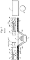
- Fig. 1 is a schematic front view of a control panel for a system controlling two parameters or variables.
- Figs. 2-4 are views similar to Fig. 1, depicting the same panel in different operating states.
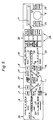
- Fig 5. is a view similar to Fig. 1 but depicting a larger panel according to the present invention for control of a plurality of different parameters in a dialysis system.
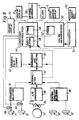
- Fig 6. is a schematic functional diagram of the elements in a system incorporating the control panel of Figs. 1-4.
- Figs. 1-4 show a control panel which is arranged for the control of two variables or parameters in a dialysis system which includes a dialyzer, a dialysis fluid inlet line, a dialysis fluid outlet line and a dialysis fluid bypass line for directly connecting the inlet line to the outlet line, and hence bypassing the dialyzer.
- the control panel includes a pictorial representation of the actual fluid flow path in the system, and hence includes a pictorial element 1 representing the dialyzer, pictorial elements 2 and 2a representing the fluid inlet lines to the dialyzer, and pictorial elements 3 and 3a representing the fluid outlet lines. Also, a pictorial representation 4 depicts a bypass line.
- a bypass alarm signal light 5 is provided between the pictorial representation 4 of the bypass line and the pictorial representation 1 of the dialyzer itself.
- a single manually rotatable knob or maneuvering element 6 is disposed on the front surface of the panel.
- Display 9 is thus associated with a parameter denominated "xxx”, which pertains to the conditions prevailing at the inlet conduit 2
- graphic display 10 is associated with a parameter denominated "yyy,” which pertains to the conditions prevailing at the outlet conduit 3.
- Graphic display 9 is disposed adjacent inlet conduit 2 and includes a common linear scale 9a with associated numerals.
- the display also includes illuminated indicia 7a, 7c and 7d, representing the values of control constants for parameter xxx, in this case the set point represented by indicia 7a, the lower limit represented by indicia 7c, and the upper limit represented by indicia 7d.
- the positions of these indicia along scale 9a represent the values of these control constants.
- Graphic display 9 also includes a bar display 7b for displaying the actual measured value of parameter xxx.
- the length of bar 7b, and hence the position of the right hand edge of the bar along scale 9a represents the actual value of parameter xxx.
- a manually operable actuator or button 7, marked with the name of the parameter or "xxx”, is disposed adjacent display 9.
- the display 10 for parameter yyy is disposed adjacent the pictorial representation 3 of the outlet conduit.
- Display 10 is generally similar to display 9, and includes a scale lOa, illuminated indicators 8a, 8c and 8d for displaying the set point, lower limit and upper limit for parameter yyy, and a bar graph 8b for indicating the actual value of parameter yyy.
- An actuator 8 is disposed adjacent display 10 and is labeled with the name of the associated parameter yyy.
- control constant selector buttons 12 which include an upper limit selector button 12' and a lower limit selector button 12", both disposed adjacent manually rotatable knob or maneuvering element 6.
- An alphanumeric display 11 is disposed on the panel face immediately above knob 6.
- actuators 7 and 8 are linked to parameter selection means 31, which in turn is connected to interpretation means 32.
- Maneuvering element knob 6 is linked to a potentiometer 34, which in turn is connected to an analog-to-digital converter 36.
- Converter 36 is also connected to interpretation apparatus 32.
- Control constant selector buttons 12' and 12" are linked to control constant selection means 38 which is also linked to interpretation means 32.
- Interpretation means 32 is in turn connected to a comparison and substitution apparatus 40, which is linked to a bounding value storage register 42.
- the control system includes a supervisory microprocessor 44 incorporating a storage register 46 and duplication means 48.
- the control system also includes a control microprocessor 50 incorporating a further storage register 52. Both of the microprocessors are linked to transducers 54 arranged to measure the actual values of the various operating parameters of the actual system.
- Supervisory microprocessor 44 is arranged to control graphic displays 9 and 10 and bypass alarm 5.
- the supervisory microprocessor is also arranged to control pictorial illumination unit 56 so as to selectively illuminate each segment of the pictorial representation 1, 2, 2a, 3, 3a and 4 with red light or with green light, as instructed by the supervisory micro-processor, or to leave each segment unilluminated.
- the supervisory microprocessor is also connected, via appropriate drivers (not shown) to illuminators 58 and 60 disposed physically within actuator buttons 7 and 8.
- the control microprocessor 50 is linked to alphanumeric display 11, and is also to linked to the adjustable element 62 of the dialyzer and associated flow conduits.
- adjustable elements typically include valves, variable electric resistance heaters, and the like.
- parameter selection means 31, interpretation means 32, control constant selection means 38, analog-to-digital converter 36, bounding value storage means 42, and comparison and substitution means 40 are illustrated in Figs. 6 as being separate from the microprocessors, it should be clearly understood that such depiction is solely for the sake of clarity of illustration. In actual practice, some or all of these elements can actually be incorporated in one or both of the microprocessors.
- Figure 1 illustrates the condition of the panel face during normal operation, without adjustment of any of the control constants.
- illuminators 58 and 60 (Fig. 6) are inactive, so that actuator buttons 7 and 8 are not illuminated.
- Pictorial illumination means 36 (Fig. 6) illuminates the pictorial representations of the dialyzer 1, the inlet conduits 2 and 2a, and the outlet conduits 3 and 3a with green light, and leaves the pictorial representation 4 of the bypass conduit unilluminated.
- the bypass alarm light 5 is likewise unilluminated.
- Alphanumeric display 11 is blank, and graphic display 9 is actuated to display the values of set point, lower limit and upper limit for parameter xxx stored in the storage register 46 of the supervisory microprocessor 44, and also to display the actual value of parameter xxx as measured by the transducers 54.
- graphic display 10 displays the set point, lower limit and upper limit for parameter yyy, also as stored in register 46, and also displays the actual value of parameter yyy.
- Figure 2 illustrates the condition of the panel during adjustment by the operator of the set point for parameter yyy.
- parameter selection means 31 selects parameter yyy. This selection is conveyed to supervisory microprocessor 44, which in turn instructs graphic display to flash the illuminated indicia 8a, 8c and 8d, for the control constants associated with parameter yyy.
- control constant selection means 38 selects the set point for parameter yyy, rather than the upper limit or lower limit for that parameter as the particular control constant to be adjusted, and signals interpretation means accordingly.
- the interpretation means thus interprets the manually variable signal generated by manual adjustment of maneuvering element or knob 6 and operation of analog-to-digital converter 36 as a new value for the set point for parameter yyy.
- the new value of parameter yyy is passed to comparison and substitution means 40.
- the comparison and substitution means compares the new value with preset, invariant upper and lower bounding values for the set point of parameter yyy stored in bounding value storage means 42. If the new value of the set point generated by interpretation means 32 is outside the range defined by these bounding values, then the comparison and substitution means 40 would substitute a value within such a range for the new value generated by the interpretation means.
- Microprocessor 44 is arranged so that the new values are entered into register 46 and then copied from that register by duplication means 48 into register 52.
- Control microprocessor 50 drives alphanumeric display 11 to show both the actual measured value of parameter yyy, as obtained from transducers 54, and also to show the value of the set point for this parameter last entered into register 52. Because the values of the set point are duplicated digitally, the exact same value will be stored in register 46 and in register 52. Moreover, because the value as stored in register 52 is fed back to the operator via alphanumeric display 11, as illustrated in Fig. 2, the operator will control his actuation of knob 6 according to the set point values as actually input into the storage registers.
- the supervisory microprocessor adjusts the position of the indicia 8a for the set point along the scale 10a of display 10, so as to reflect the new set point value.
- the control microprocessor 50 will compare the actual value of parameter yyy from the transducers from the new set point and will adjust the system adjuster components 62 to drive the actual value of this parameter towards the set point value.
- control constant selection means 38 selects the upper limit control constant for adjustment.
- the interpretation means will interpret these signals derived from manually adjustable maneuvering element or knob 8 via potentiometer 34 and converter 36 as a new value for the upper limit of parameter yyy.
- the comparison and substitution means will compare the new value with bounding values appropriate to the upper limit, rather than to the set point for parameter yyy and control microprocessor 50 will cause alphanumeric display 11 to display both the actual value of parameter yyy and the new upper limit value input into and stored in register 52.
- variable signal derived from operation of knob 6 will be interpreted as a new value for the lower limit of parameter yyy.
- the same action pertains to the setting of those parameters which requires actuation of button 7, rather than button 8.
- the signal derived from operation of knob 6 is interpreted as a new value for the particular control constant selected by the control constant selection means for the particular parameter selected by the parameter selection means.
- the identity of the parameter and of the control constant being set is displayed, along with the value of the constant as set, on alphanumeric display 11.
- Figure 3 illustrates the appearance of the front panel when parameter yyy falls outside the upper and lower limits associated with that parameter, and the control microprocessor adjusts the system to bypass the dialyzer.
- the bar graph 8b reflecting the actual measured value of parameter yyy shows the out-of-limit value.
- the right hand edge of the bar graph is at a low level on the scale lOa and is outside the range encompassed by indicia 8a and 8d, corresponding to the lower and upper limits, respectively.
- supervisory microprocessor 44 causes illuminator 60 to illuminate actuator 8 with a red light.
- the supervisory microprocessor illuminates bypass alarm indicator 5.
- the supervisory microprocessor also adjusts pictorial illumination means 56 to illuminate the pictorial representation 2 of the inlet conduit, the pictorial representation 4 of the bypass conduit, and the pictorial representation 3 of the outlet conduit with a red light.
- the pictorial representations 2a and 3a of the branch conduits leading to and from the dialyzer are left unilluminated.
- the red color of the illuminated representation provides a further signal that the bypass condition is the result of an abnormal, out-of-limit condition. These signals are supplemented by the bypass alarm light 5.
- the alarm indication provided by illuminated actuator 8 guides the operator to instant identification of the particular parameter which is out-of limits, and which has caused the abnormal condition.
- the system may be deliberately switched into a bypass mode, for example as part of a predetermined schedule of operation, and this can be done even where none of the parameters is in an out-of-limit condition.
- the illuminators associated with actuators 7 and 8 are left unilluminated, so that no alarm signal is given.
- the pictorial representation means is adjusted by the supervisory microprocessor to illuminate pictorial representations 2, 3 and 4 to show the bypass flow, and to leave representations 2a and 3a unilluminated to show that no flow is going through the dialyzer, the pictorial representation is illuminated in green light, rather than red light. Thus, whether or not there is an alarm condition, the pictorial representation can be employed to show the actual flow path in use within the system.
- Figure 5 thus depicts the front face of a control panel, as can be used in controlling dialysis fluid flow in a hemodialysis system.
- the panel of Fig. 5 incorporates the same elements as mentioned above in connection with Figs. 1-4 and 6. Elements common to both embodiments are denoted in Fig. 5 by the same reference numerals as those employed in Figs. 1-4 and 6.
- display 9 is associated in Fig. 5 with the real parameter of fluid conductivity, and the associated adjacent actuator 7 is marked with the legend "COND”, rather than with the nominal legend "xxx" appearing on the corresponding actuator appearing in Fig. 2.
- the graphic display 10 is associated with the real parameter transmembrane pressure, and the associated adjacent actuator 8 is marked with the legend "TMP", rather than with the nominal legend "yyy,” as in the other figures.
- the pictorial representation on the front face of the panel in Fig. 5 includes the same elements as the pictorial representation of Figs. 1-4, but also includes a pictorial representation 13 of an additional branch conduit carrying an ultrafiltrate flow.
- Additional graphic representations 22 and 23 associated with ultrafiltrate volume and ultrafiltration rate parameters, both of which pertain to the flow in the ultrafiltrate conduit represented by branch 13, are disposed on the panel front face adjacent this branch of the pictorial representation.
- Actuators 18 and 19 which are associated, respectively, with ultrafiltrate volume and ultrafiltration rate, are disposed adjacent to graphic displays 22 and 23, respectively.
- additional graphic displays 20 and 21 for incoming dialysis fluid temperature in the inlet represented by pictorial representation 2, and fluid flow in the inlet 2, respectively, are disposed adjacent to the pictorial representation of the inlet conduit. Actuators 14 and 15 relating to these parameters are disposed adjacent to these additional displays.
- buttons 26 for setting the system to operate in different modes.
- each of these buttons may be linked to the control and supervisory microprocessors of the system, so that these microprocessors, and hence the system as a whole, can operate according to different programs, depending upon which of the buttons is actuated.
- depression of the button 26 marked “TMP Mode” sets the system to operate so as to maintain the transmembrane pressure constant
- operation of the button 26 marked “Auto UF Mode” sets the system to perform a dialysis procedure with accurately controlled ultrafiltration.
- Operation of the button marked “Isolated UF Mode” sets the system to perform a pure ultrafiltration procedure without any dialysis fluid flow.
- the buttons marked "HEAT DISNF”, “CHEM DISNF”, “RINSE” and “DRAIN” sets the system to perform the corresponding heat sterilization, chemical sterilization, rinsing or emptying of functions.
- the panel of Fig. 5 also includes a clock display 27.
- This clock display is associated with and adjacent to an actuator 16 marked "TIME”. Operation of this actuator combined with adjustment of the knob or maneuvering element 6 sets the time of internal clocks within the microprocessors of the system.
- the panel of Fig. 5 also includes additional displays for showing information other than the values and control constants for the parameters set from the panel.
- digital display 28 marked “WATER LEV” indicates the fluid level in a vessel for containing dialysis fluid.
- the panel of Fig. 5 also includes a start button 24 and a button 25 marked “CONFIRM” disposed adjacent maneuvering element or knob 6.
- Operation of the panel shown in Fig. 5 is substantially the same as operation of the panel described above with reference to Figs. 1-4 and 6.
- the operator actuates actuator 8 adjacent display 10 for transmembrane pressure, and also actuates the high limit button 12' adjacent to maneuvering element or knob 6.
- the variable signal produced upon actuation of this element is interpreted as a new value for the transmembrane pressure upper limit, which is displayed on alphanumeric display 11.
- the control system does not begin to apply the new value so set until the operator signals that he is satisfied with the new value displayed on display 11 by pressing CONFIRM button 25.
- each of the storage registers associated with the microprocessors may be provided with a temporary storage location, distinct from the storage locations for the parameters actually in use, and each microprocessor may be arranged to shift the newly set value from the temporary storage location to the storage location assigned to the parameter when the CONFIRM button is depressed.
- the upper and lower limits are not set directly. Instead, the system is arranged to calculate upper and lower limits for each parameter from the set point selected by the operator for such parameter.
- the upper and lower limits may be calculated from the set point according to a predetermined formula or algorithm.
- the control constant selection means may be omitted and the high limit and low limit selector buttons 12' and 12" may likewise be omitted.
- the layout of the fluid flow path and the control panel face may make it impossible to dispose each graphic display and the associated actuator immediately adjacent the pictorial representation of the pertinent portion of the fluid flow path.
- some of the graphic displays may be disposed adjacent related pictorial representations, whereas other graphic displays may be disposed at more remote locations.
- the pictorial representation may be omitted entirely, and the graphic displays may be replaced by other forms of display.
- alphanumeric display 11 may be omitted entirely, and the supervisory microprocessor may be arranged to display the new value set for each control constant only on the related graphic display.
- control panel in control of the dialysis fluid portion of a hemodialysis system, should be arranged to set control constants for one or more of the following functions: conductivity, temperature, fluid flow, transmembrane pressure, ultrafiltrate volume, ultrafiltration rate, time, chemical composition, pH and blood leakage monitoring.
- control constants for one or more of the following parameters should be set by use of a control panel in accordance with the present invention: temperature, blood flow, transmembrane pressure, venous pressure, arterial pressure, chemical composition and the presence of air.
- control panel is configured to control both blood handling portion and the hemodialysis fluid flow portion of the system.
- a control panel for such use would typically incorporate pictorial representations of the flow paths for both blood and dialysis fluid.
- the present invention provides important improvements in monitoring and control of operating parameters in hemodialysis fluid flow and/or blood flow in hemodialysis operations, the invention provides improved methods of controlling these functions.
- control panels and systems in accordance with the present invention are employed and operated as described above.
- the comparison and substitution means checks the new value for every control constant.
- the apparatus can be arranged so that the less significant or noncritical control constants are not so checked.
Landscapes
- Health & Medical Sciences (AREA)
- Engineering & Computer Science (AREA)
- General Physics & Mathematics (AREA)
- Automation & Control Theory (AREA)
- Physics & Mathematics (AREA)
- Heart & Thoracic Surgery (AREA)
- Urology & Nephrology (AREA)
- Biomedical Technology (AREA)
- Vascular Medicine (AREA)
- Anesthesiology (AREA)
- Emergency Medicine (AREA)
- Hematology (AREA)
- Life Sciences & Earth Sciences (AREA)
- Animal Behavior & Ethology (AREA)
- General Health & Medical Sciences (AREA)
- Public Health (AREA)
- Veterinary Medicine (AREA)
- External Artificial Organs (AREA)
- Feedback Control In General (AREA)
- Control By Computers (AREA)
Claims (10)
- Procédé de mise au point de valeurs pour un appareil de réglage comprenant :caractérisé en ce qu'il comprend les opérations consistant :au moins deux microprocesseurs,un premier de ces microprocesseurs étant agencé de façon à régler certains paramètres, en liaison avec des premières constantes de réglage rangées dans un premier registre de mémoire associé au premier microprocesseur,un second desdits microprocesseurs étant agencé de façon à surveiller lesdits paramètres en liaison avec des secondes constantes de réglage rangées dans un second registre de mémoire associé au second microprocesseur, essentiellement en vue de superviser lesdits paramètres,des moyens d'entrée réglables manuellement servant à envoyer des valeurs desdites constantes de réglage aux registres de mémoire respectifs,à faire actionner les moyens d'entrée par un opérateur de façon que de nouvelles valeurs correspondant aux constantes de réglage à introduire soient envoyées, en tant que nouvelles constantes de réglage, dans l'un des registres constitués par le premier registre de mémoire et le second registre de mémoire,à procéder ensuite à une duplication numérique des nouvelles constantes de réglage telles qu'entrées dans ledit premier registre de mémoire à partir de ce registre et à introduire dans un autre des registres de mémoire les nouvelles constantes de réglage obtenues par duplication, de sorte que ce sont des valeurs identiques des nouvelles constantes de réglage qui sont introduites dans tous les registres de mémoire,et à réaliser finalement une visualisation des nouvelles constantes de réglage obtenues par duplication, de façon à offrir une rétroaction à l'opérateur.
- Procédé selon la revendication 1, caractérisé en ce qu'il comprend en outre les opérations consistant à contrôler les nouvelles valeurs fournies par les moyens d'entrée et éventuellement à les corriger de façon qu'elles soient situées entre des valeurs limites préfixées, avant qu'elles soient approuvées et introduites dans le premier registre de mémoire en tant que nouvelles constantes de réglage.
- Procédé selon la revendication 1 ou 2, caractérisé en ce qu'il comprend les opérations consistant à mesurer lesdits paramètres au moyen de premiers transducteurs associés au premier microprocesseur et au moyen de seconds transducteurs associés au second microprocesseur et à comparer d'une manière indépendante les valeurs de paramètre, mesurées, aux constantes de réglage rangées dans le registre de mémoire associé.
- Procédé selon la revendication 3, selon lequel des éléments réglables influent sur lesdits paramètres, caractérisé en ce qu'il comprend les opérations consistant à comparer un échantillon d'un paramètre donné, prélevé par le premier transducteur associé, aux constantes de réglage rangées dans ledit registre de mémoire et à envoyer aux éléments réglables un signal de réglage permettant de régler ledit paramètre de façon qu'il prenne une valeur donnée par les constantes de réglage et/ou de façon qu'il soit compris entre certaines valeurs limites données par les constantes de réglage et en ce que le second microprocesseur est agencé de façon à comparer un échantillon prélevé par le second transducteur associé, aux constantes de réglage rangées dans le second registre de mémoire, de façon à fournier un signal d'alarme lorsque l'échantillon est situé en dehors des valeurs limites données par les constantes de réglage.
- Appareil de réglage permettant de mettre en oeuvre un procédé selon l'une des revendications 1 à 4, comprenant :caractérisé en ce que :au moins deux microprocesseurs (44, 50),un premier de ces microprocesseurs (50) étant agencé de façon à régler certains paramètres (XXX, YYY) en liaison avec des premières constantes de réglage rangées dans un premier registre de mémoire (52) associé au premier microprocesseur,un second desdits microprocesseurs (44) étant agencé de façon à surveiller lesdits paramètres en liaison avec des secondes constantes de réglage rangées dans un second registre de mémoire (46) associé au second microprocesseur, essentiellement en vue de superviser lesdits paramètres,des moyens d'entrée (6) réglables manuellement servant à envoyer des valeurs desdites constantes de réglage aux registres de mémoire respectifs,les moyens d'entrée (6) sont agencés de manière à être actionnés par un opérateur de façon que de nouvelles valeurs des constantes de réglage à introduire soient envoyées, en tant que nouvelles constantes de réglage, dans l'un des registres constitués par le premier registre de mémoire et le second registre de mémoire (46-52),des moyens de duplication numérique (48) servant à réaliser ensuite une duplication numérique des nouvelles constantes de réglage telles qu'entrées dans ledit premier registre de mémoire à partir de ce registre et à introduire dans un autre des registres de mémoire (46-52) les nouvelles constantes de réglage obtenues par duplication, de sorte que ce sont des valeurs identiques des nouvelles constantes de réglage qui sont introduites dans tous les registres de mémoire, etdes moyens de visualisation (11) permettant finalement de visualiser les nouvelles constantes de réglage obtenues par duplication, de façon à offrir une rétroaction à l'opérateur.
- Appareil de réglage selon la revendication 5, caractérisé par des moyens (40, 42) servant à contrôler les nouvelles valeurs fournies par les moyens d'entrée, et éventuellement les corriger de façon qu'elles soient situées entre des valeurs limites préfixées, avant qu'elles soient approuvées et introduites dans le premier registre de mémoire en tant que nouvelles constantes de réglage.
- Appareil de réglage selon la revendication 5 ou 6, caractérisé en ce que lesdits paramètres sont mesurés au moyen de premiers transducteurs (54) associés au premier microprocesseur et au moyen de seconds transducteurs (54) associés au second microprocesseur, les microprocesseurs étant agencés de façon à comparer d'une manière indépendante les valeurs de paramètre mesurées aux constantes de réglage rangées dans le registre de mémoire associé.
- Appareil de réglage selon la revendication 6 ou 7, dans lequel des éléments ajustables (62) influent sur lesdits paramètres, caractérisé en ce que le premier microprocesseur est agencé de façon à comparer un échantillon d'un paramètre donné, prélevé au moyen du premier transducteur associé, aux constantes de réglage rangées dans ledit registre de mémoire, de façon à fournir auxdits moyens d'actionnement un signal de réglage servant à ajuster le paramètre de façon qu'il prenne une valeur donnée par les constantes de réglage et/ou de façon qu'il soit situé entre certaines valeurs limites données par les constantes de réglage, et en ce que le second microprocesseur est agencé de façon à comparer un échantillon, prélevé au moyen du second détecteur associé, aux constantes de réglage rangées dans le second registre de mémoire, de façon à fournir un signal d'alarme (5) lorsque ledit échantillon est situé en dehors des valeurs limites données par les constantes de réglage.
- Appareil de réglage selon l'une quelconque des revendications 5 à 8, caractérisé en ce que les moyens de duplication numérique (48) font partie de l'un (44) des microprocesseurs (44, 50).
- Appareil de réglage selon l'une quelconque des revendications 5 à 9, caractérisé en ce que ledit paramètre est sélectionné dans le groupe constitué par les conductibilité, température, débit de fluide, pression transmembranaire, volume de produit d'ultrafiltration, vitesse d'ultrafiltration, temps, composition chimique, pH et pertes de sang.
Applications Claiming Priority (3)
| Application Number | Priority Date | Filing Date | Title |
|---|---|---|---|
| SE8502756 | 1985-06-04 | ||
| SE8502756A SE457388B (sv) | 1985-06-04 | 1985-06-04 | Monitor foer styrning och/eller kontroll av tvaa eller flera funktioner samt anvaendning av en saadan foer styrning av en vaetskestroem |
| EP86107235A EP0204260B1 (fr) | 1985-06-04 | 1986-05-28 | Dispositif de commande et/ou de contrôle de fonctions multiples |
Related Parent Applications (2)
| Application Number | Title | Priority Date | Filing Date |
|---|---|---|---|
| EP86107235A Division EP0204260B1 (fr) | 1985-06-04 | 1986-05-28 | Dispositif de commande et/ou de contrôle de fonctions multiples |
| EP86107235.3 Division | 1986-05-28 |
Publications (4)
| Publication Number | Publication Date |
|---|---|
| EP0428505A2 EP0428505A2 (fr) | 1991-05-22 |
| EP0428505A3 EP0428505A3 (en) | 1991-10-09 |
| EP0428505B1 EP0428505B1 (fr) | 1995-12-20 |
| EP0428505B2 true EP0428505B2 (fr) | 2001-03-14 |
Family
ID=20360442
Family Applications (3)
| Application Number | Title | Priority Date | Filing Date |
|---|---|---|---|
| EP86107235A Expired - Lifetime EP0204260B1 (fr) | 1985-06-04 | 1986-05-28 | Dispositif de commande et/ou de contrôle de fonctions multiples |
| EP91102481A Expired - Lifetime EP0428505B2 (fr) | 1985-06-04 | 1986-05-28 | Dispositif de commande |
| EP19910102527 Withdrawn EP0432138A3 (en) | 1985-06-04 | 1986-05-28 | A control panel |
Family Applications Before (1)
| Application Number | Title | Priority Date | Filing Date |
|---|---|---|---|
| EP86107235A Expired - Lifetime EP0204260B1 (fr) | 1985-06-04 | 1986-05-28 | Dispositif de commande et/ou de contrôle de fonctions multiples |
Family Applications After (1)
| Application Number | Title | Priority Date | Filing Date |
|---|---|---|---|
| EP19910102527 Withdrawn EP0432138A3 (en) | 1985-06-04 | 1986-05-28 | A control panel |
Country Status (5)
| Country | Link |
|---|---|
| US (1) | US4990258A (fr) |
| EP (3) | EP0204260B1 (fr) |
| JP (2) | JP2693147B2 (fr) |
| DE (2) | DE3686443T2 (fr) |
| SE (3) | SE457388B (fr) |
Cited By (15)
| Publication number | Priority date | Publication date | Assignee | Title |
|---|---|---|---|---|
| US6533804B2 (en) | 1998-01-23 | 2003-03-18 | Innercool Therapies, Inc. | Inflatable catheter for selective organ heating and cooling and method of using the same |
| US6551349B2 (en) | 1998-03-24 | 2003-04-22 | Innercool Therapies, Inc. | Selective organ cooling apparatus |
| US6585752B2 (en) | 1998-06-23 | 2003-07-01 | Innercool Therapies, Inc. | Fever regulation method and apparatus |
| US6660028B2 (en) | 2000-06-02 | 2003-12-09 | Innercool Therapies, Inc. | Method for determining the effective thermal mass of a body or organ using a cooling catheter |
| US6676688B2 (en) | 1998-01-23 | 2004-01-13 | Innercool Therapies, Inc. | Method of making selective organ cooling catheter |
| US6676690B2 (en) | 1999-10-07 | 2004-01-13 | Innercool Therapies, Inc. | Inflatable heat transfer apparatus |
| US6692488B2 (en) | 1998-01-23 | 2004-02-17 | Innercool Therapies, Inc. | Apparatus for cell necrosis |
| US6702842B2 (en) | 1998-01-23 | 2004-03-09 | Innercool Therapies, Inc. | Selective organ cooling apparatus and method |
| US6905509B2 (en) | 1998-01-23 | 2005-06-14 | Innercool Therapies, Inc. | Selective organ cooling catheter with guidewire apparatus and temperature-monitoring device |
| US7004960B2 (en) | 2000-11-07 | 2006-02-28 | Innercool Therapies, Inc. | Circulation set for temperature-controlled catheter and method of using the same |
| US7018399B2 (en) | 1998-06-23 | 2006-03-28 | Innercool Therapies, Inc. | Method of making selective organ cooling catheter |
| US7139622B2 (en) | 2001-02-20 | 2006-11-21 | Pilz Gmbh & Co. | Method and device for programming a failsafe control system |
| US7300453B2 (en) | 2003-02-24 | 2007-11-27 | Innercool Therapies, Inc. | System and method for inducing hypothermia with control and determination of catheter pressure |
| US7371254B2 (en) | 1998-01-23 | 2008-05-13 | Innercool Therapies, Inc. | Medical procedure |
| US7458984B2 (en) | 1998-01-23 | 2008-12-02 | Innercool Therapies, Inc. | System and method for inducing hypothermia with active patient temperature control employing catheter-mounted temperature sensor and temperature projection algorithm |
Families Citing this family (82)
| Publication number | Priority date | Publication date | Assignee | Title |
|---|---|---|---|---|
| DE3810186A1 (de) * | 1987-08-01 | 1989-10-05 | Siegert Gmbh | Sensor zur messung der aktivitaet von ionen, sowie verfahren zu dessen herstellung |
| US5291190A (en) * | 1991-03-28 | 1994-03-01 | Combustion Engineering, Inc. | Operator interface for plant component control system |
| US5486286A (en) | 1991-04-19 | 1996-01-23 | Althin Medical, Inc. | Apparatus for performing a self-test of kidney dialysis membrane |
| US5326476A (en) * | 1991-04-19 | 1994-07-05 | Althin Medical, Inc. | Method and apparatus for kidney dialysis using machine with programmable memory |
| IT1255260B (it) * | 1991-07-16 | 1995-10-20 | Hospal Dasco Spa | Metodo di sorveglianza di una terapia in un trattamento dialitico. |
| JP2862036B2 (ja) * | 1991-09-17 | 1999-02-24 | 三菱電機株式会社 | 数値制御装置 |
| IT1250558B (it) * | 1991-12-30 | 1995-04-20 | Hospal Dasco Spa | Macchina per dialisi con controllo della sicurezza e relativo metodo di controllo della sicurezza. |
| US5278149A (en) * | 1992-01-17 | 1994-01-11 | New England Deaconess Hospital Corporation | Method of preparing total parenteral nutrition solutions |
| EP0597817B1 (fr) * | 1992-11-12 | 2003-07-09 | Baxter International Inc. | Méthode et appareillage pour dialyse rénale |
| US6822563B2 (en) | 1997-09-22 | 2004-11-23 | Donnelly Corporation | Vehicle imaging system with accessory control |
| US5350357A (en) * | 1993-03-03 | 1994-09-27 | Deka Products Limited Partnership | Peritoneal dialysis systems employing a liquid distribution and pumping cassette that emulates gravity flow |
| US5438510A (en) * | 1993-03-03 | 1995-08-01 | Deka Products Limited Partnership | User interface and monitoring functions for automated peritoneal dialysis systems |
| US5431626A (en) * | 1993-03-03 | 1995-07-11 | Deka Products Limited Partnership | Liquid pumping mechanisms for peritoneal dialysis systems employing fluid pressure |
| US5324422A (en) * | 1993-03-03 | 1994-06-28 | Baxter International Inc. | User interface for automated peritoneal dialysis systems |
| US5685988A (en) * | 1993-09-15 | 1997-11-11 | Malchesky; Paul | Dialysis process and system |
| US5709670A (en) * | 1994-05-03 | 1998-01-20 | Aquintel, Inc. | Surgical fluid and tissue loss monitor |
| US5507723A (en) * | 1994-05-24 | 1996-04-16 | Baxter International, Inc. | Method and system for optimizing dialysis clearance |
| US5609770A (en) * | 1995-06-07 | 1997-03-11 | Cobe Laboratories, Inc. | Graphical operator machine interface and method for information entry and selection in a dialysis machine |
| US5620608A (en) * | 1995-06-07 | 1997-04-15 | Cobe Laboratories, Inc. | Information entry validation system and method for a dialysis machine |
| US5618441A (en) * | 1995-06-07 | 1997-04-08 | Rosa; Jim | Single microcontroller execution of control and safety system functions in a dialysis machine |
| FR2771825B1 (fr) * | 1997-11-28 | 2001-06-08 | Crouzet Automatismes | Appareil electrique a fonction parametrable a cout reduit |
| US6845271B2 (en) * | 1998-06-03 | 2005-01-18 | Neurocontrol Corporation | Treatment of shoulder dysfunction using a percutaneous intramuscular stimulation system |
| US8626302B2 (en) * | 1998-06-03 | 2014-01-07 | Spr Therapeutics, Llc | Systems and methods to place one or more leads in muscle for providing electrical stimulation to treat pain |
| US6952808B1 (en) | 1999-07-01 | 2005-10-04 | Honeywell Inc. | Process variable gauge interface and methods regarding same |
| US6901560B1 (en) | 1999-07-01 | 2005-05-31 | Honeywell Inc. | Process variable generalized graphical device display and methods regarding same |
| EP1121951A1 (fr) * | 2000-02-01 | 2001-08-08 | Uvo M. Prof. Hölscher Ph. D. | Circuit - Système de regulation pour la thérapie d'un patient |
| WO2001056631A2 (fr) * | 2000-02-01 | 2001-08-09 | Uvo Hoelscher | Concept de securite pour une boucle de regulation servant au dosage dynamique de medicaments |
| US6497676B1 (en) | 2000-02-10 | 2002-12-24 | Baxter International | Method and apparatus for monitoring and controlling peritoneal dialysis therapy |
| IT1320264B1 (it) | 2000-09-29 | 2003-11-26 | Gambro Dasco Spa | Apparecchiatura di dialisi e metodo di verifica della funzionalita' diuna apparecchiatura di dialisi. |
| US6625494B2 (en) | 2001-03-30 | 2003-09-23 | Neurocontrol Corporation | Systems and methods for performing prosthetic or therapeutic neuromuscular stimulation using a universal external controller providing different selectable neuromuscular stimulation functions |
| US6678563B2 (en) | 2001-03-30 | 2004-01-13 | Neurocontrol Corporation | Systems and methods for performing prosthetic or therapeutic neuromuscular stimulation using a universal external controller having a graphical user interface |
| US6587728B2 (en) | 2001-03-30 | 2003-07-01 | Neurocontrol Corporation | Systems and methods for performing prosthetic or therapeutic neuromuscular stimulation using an external, battery powered controller with power conservation features |
| US6701189B2 (en) | 2001-03-30 | 2004-03-02 | Neurocontrol Corporation | Systems and methods for performing prosthetic or therapeutic neuromuscular stimulation using a universal external controller accommodating different control inputs and/or different control outputs |
| SE523610C2 (sv) * | 2001-10-02 | 2004-05-04 | Gambro Lundia Ab | Metod vid styrning av dialysanordning |
| US20030125662A1 (en) | 2002-01-03 | 2003-07-03 | Tuan Bui | Method and apparatus for providing medical treatment therapy based on calculated demand |
| US7153286B2 (en) | 2002-05-24 | 2006-12-26 | Baxter International Inc. | Automated dialysis system |
| EP1847282B1 (fr) * | 2002-05-24 | 2011-03-23 | Baxter International Inc. | Système de fluide médicale avec affichage |
| US7175606B2 (en) | 2002-05-24 | 2007-02-13 | Baxter International Inc. | Disposable medical fluid unit having rigid frame |
| US6939111B2 (en) | 2002-05-24 | 2005-09-06 | Baxter International Inc. | Method and apparatus for controlling medical fluid pressure |
| US7238164B2 (en) | 2002-07-19 | 2007-07-03 | Baxter International Inc. | Systems, methods and apparatuses for pumping cassette-based therapies |
| US20040111293A1 (en) * | 2002-12-09 | 2004-06-10 | Catherine Firanek | System and a method for tracking patients undergoing treatment and/or therapy for renal disease |
| US7890341B2 (en) * | 2002-12-09 | 2011-02-15 | Baxter International Inc. | System and a method for providing integrated access management for peritoneal dialysis and hemodialysis |
| US8029454B2 (en) * | 2003-11-05 | 2011-10-04 | Baxter International Inc. | High convection home hemodialysis/hemofiltration and sorbent system |
| ES2427513T3 (es) * | 2003-12-18 | 2013-10-30 | Gambro Lundia Ab | Aparato para determinar un parámetro de paciente o tratamiento o aparato durante un tratamiento de sangre extracorporal |
| GB0503466D0 (en) * | 2005-02-18 | 2005-03-30 | Newage Int Ltd | Adjustment and display of stored parameters |
| ATE464611T1 (de) * | 2005-06-09 | 2010-04-15 | Gambro Lundia Ab | Medizinische vorrichtung und verfahren zum einrichten einer medizinischen vorrichtung |
| EP1929381B1 (fr) * | 2005-07-04 | 2010-03-24 | VKR Holding A/S | Systeme et procede de manipulation de limites |
| EP2248545B1 (fr) * | 2005-08-25 | 2014-03-05 | Gambro Lundia AB | Appareil médical |
| US8870812B2 (en) | 2007-02-15 | 2014-10-28 | Baxter International Inc. | Dialysis system having video display with ambient light adjustment |
| US7909795B2 (en) | 2007-07-05 | 2011-03-22 | Baxter International Inc. | Dialysis system having disposable cassette and interface therefore |
| US8040493B2 (en) | 2007-10-11 | 2011-10-18 | Fresenius Medical Care Holdings, Inc. | Thermal flow meter |
| US9358331B2 (en) | 2007-09-13 | 2016-06-07 | Fresenius Medical Care Holdings, Inc. | Portable dialysis machine with improved reservoir heating system |
| US8597505B2 (en) | 2007-09-13 | 2013-12-03 | Fresenius Medical Care Holdings, Inc. | Portable dialysis machine |
| US8240636B2 (en) | 2009-01-12 | 2012-08-14 | Fresenius Medical Care Holdings, Inc. | Valve system |
| US8105487B2 (en) | 2007-09-25 | 2012-01-31 | Fresenius Medical Care Holdings, Inc. | Manifolds for use in conducting dialysis |
| US9308307B2 (en) | 2007-09-13 | 2016-04-12 | Fresenius Medical Care Holdings, Inc. | Manifold diaphragms |
| US8535522B2 (en) * | 2009-02-12 | 2013-09-17 | Fresenius Medical Care Holdings, Inc. | System and method for detection of disconnection in an extracorporeal blood circuit |
| US7905853B2 (en) | 2007-10-30 | 2011-03-15 | Baxter International Inc. | Dialysis system having integrated pneumatic manifold |
| CA3057807C (fr) | 2007-11-29 | 2021-04-20 | Thomas P. Robinson | Systeme et procede pour realiser une hemodialyse et une hemofiltration |
| US9180238B2 (en) | 2008-06-11 | 2015-11-10 | Baxter International Inc. | Distributed processing system and method for dialysis machines |
| US8062513B2 (en) | 2008-07-09 | 2011-11-22 | Baxter International Inc. | Dialysis system and machine having therapy prescription recall |
| US9514283B2 (en) | 2008-07-09 | 2016-12-06 | Baxter International Inc. | Dialysis system having inventory management including online dextrose mixing |
| AU2009302327C1 (en) | 2008-10-07 | 2015-09-10 | Fresenius Medical Care Holdings, Inc. | Priming system and method for dialysis systems |
| CA2739807C (fr) * | 2008-10-30 | 2017-02-28 | Fresenius Medical Care Holdings, Inc. | Systeme de dialyse portatif modulaire |
| WO2010114932A1 (fr) | 2009-03-31 | 2010-10-07 | Xcorporeal, Inc. | Ensemble réservoir modulaire pour un système d'hémodialyse et d'hémofiltration |
| US20110141116A1 (en) * | 2009-12-16 | 2011-06-16 | Baxter International Inc. | Methods and apparatus for displaying flow rate graphs and alarms on a dialysis system |
| WO2011138918A1 (fr) * | 2010-05-06 | 2011-11-10 | 日清オイリオグループ株式会社 | Composition de graisse et son procédé de production |
| US8788048B2 (en) | 2010-11-11 | 2014-07-22 | Spr Therapeutics, Llc | Systems and methods for the treatment of pain through neural fiber stimulation |
| US8788046B2 (en) | 2010-11-11 | 2014-07-22 | Spr Therapeutics, Llc | Systems and methods for the treatment of pain through neural fiber stimulation |
| US8788047B2 (en) | 2010-11-11 | 2014-07-22 | Spr Therapeutics, Llc | Systems and methods for the treatment of pain through neural fiber stimulation |
| ITRM20110482A1 (it) * | 2011-09-14 | 2013-03-15 | Prb S R L | Cruscotto per la visualizzazione delle criticità inerenti i parametri in un controllo di processi. |
| EP2659919B1 (fr) * | 2012-05-03 | 2014-12-10 | B. Braun Avitum AG | Procédé de réglage de paramètres pertinents de sécurité dans un appareil médical et appareil médical |
| WO2014033782A1 (fr) * | 2012-08-30 | 2014-03-06 | テルモ株式会社 | Dispositif de circulation extracorporelle, dispositif de commande et procédé de commande correspondant |
| US9201036B2 (en) | 2012-12-21 | 2015-12-01 | Fresenius Medical Care Holdings, Inc. | Method and system of monitoring electrolyte levels and composition using capacitance or induction |
| US9157786B2 (en) | 2012-12-24 | 2015-10-13 | Fresenius Medical Care Holdings, Inc. | Load suspension and weighing system for a dialysis machine reservoir |
| US9354640B2 (en) * | 2013-11-11 | 2016-05-31 | Fresenius Medical Care Holdings, Inc. | Smart actuator for valve |
| EP3314488B1 (fr) | 2015-06-25 | 2024-03-13 | Gambro Lundia AB | Système et procédé de dispositif médical comprenant une base de données distribuée |
| CN105353687A (zh) * | 2015-11-28 | 2016-02-24 | 郑州飞机装备有限责任公司 | 通过临界值判断输出模拟量稳定性的方法 |
| US11540973B2 (en) | 2016-10-21 | 2023-01-03 | Spr Therapeutics, Llc | Method and system of mechanical nerve stimulation for pain relief |
| US11179516B2 (en) | 2017-06-22 | 2021-11-23 | Baxter International Inc. | Systems and methods for incorporating patient pressure into medical fluid delivery |
| CN109213040B (zh) * | 2018-09-11 | 2021-06-15 | 深圳市英威腾电气股份有限公司 | 控制电路、电子设备及其控制方法 |
| CN112266052A (zh) * | 2020-09-29 | 2021-01-26 | 华帝股份有限公司 | 一种设置滤芯剩余使用量的系统 |
Family Cites Families (13)
| Publication number | Priority date | Publication date | Assignee | Title |
|---|---|---|---|---|
| US4370983A (en) * | 1971-01-20 | 1983-02-01 | Lichtenstein Eric Stefan | Computer-control medical care system |
| US3947665A (en) * | 1974-04-22 | 1976-03-30 | Vsi Energy Systems International, Inc. | Control system and method |
| DE2429342A1 (de) * | 1974-06-19 | 1976-01-08 | Ciba Geigy Ag | Vorrichtung zur ueberwachung von insbesondere chemischen anlagen |
| US4153554A (en) * | 1977-02-22 | 1979-05-08 | American Micro-Bionics Corp. | Apparatus for use in artificial kidney system |
| US4180854A (en) * | 1977-09-29 | 1979-12-25 | Hewlett-Packard Company | Programmable calculator having string variable editing capability |
| CH623945A5 (fr) * | 1977-10-12 | 1981-06-30 | Contraves Ag | |
| US4247317A (en) * | 1978-04-20 | 1981-01-27 | Ball Corporation | Glassware forming machine computer-ram controller system |
| DE2935355A1 (de) * | 1979-09-01 | 1981-03-26 | Krauss-Maffei AG, 80997 München | Bedientafel zum einstellen des arbeitsablaufs einer rechnergesteuerten kunststoff-spritzgiessmaschine |
| GB2141838B (en) * | 1980-05-01 | 1985-07-24 | Rank Organisation Plc | Stage lighting control system |
| DE3031966C2 (de) * | 1980-08-25 | 1983-03-03 | Licentia Patent-Verwaltungs-Gmbh, 6000 Frankfurt | Einrichtung zur handbetätigten Einstellung von bestimmten Funktionen mittels eines ersten Impulsgenerators und zur ebenfalls handbetätigten Einstellung diesen zuordenbaren Daten mittels eines zweiten Impulsgenerators |
| DE3216286A1 (de) * | 1981-06-30 | 1983-01-13 | Siemens AG, 1000 Berlin und 8000 München | Elektronisches regelgeraet |
| JPS5846336U (ja) * | 1981-09-22 | 1983-03-29 | 横河電機株式会社 | 警報設定器 |
| GB2125577B (en) * | 1982-08-16 | 1986-09-24 | Nissan Motor | Self monitoring system |
-
1985
- 1985-06-04 SE SE8502756A patent/SE457388B/sv not_active IP Right Cessation
-
1986
- 1986-05-28 DE DE8686107235T patent/DE3686443T2/de not_active Expired - Lifetime
- 1986-05-28 EP EP86107235A patent/EP0204260B1/fr not_active Expired - Lifetime
- 1986-05-28 EP EP91102481A patent/EP0428505B2/fr not_active Expired - Lifetime
- 1986-05-28 EP EP19910102527 patent/EP0432138A3/en not_active Withdrawn
- 1986-05-28 DE DE3650457T patent/DE3650457T2/de not_active Expired - Lifetime
- 1986-05-28 SE SE8602423A patent/SE504658C2/sv not_active IP Right Cessation
- 1986-05-29 US US06/868,354 patent/US4990258A/en not_active Expired - Lifetime
- 1986-06-04 JP JP61130018A patent/JP2693147B2/ja not_active Expired - Fee Related
-
1990
- 1990-02-13 SE SE9000510A patent/SE504980C2/sv not_active IP Right Cessation
-
1997
- 1997-06-11 JP JP9154048A patent/JP2960373B2/ja not_active Expired - Fee Related
Cited By (28)
| Publication number | Priority date | Publication date | Assignee | Title |
|---|---|---|---|---|
| US6695873B2 (en) | 1998-01-23 | 2004-02-24 | Innercool Therapies, Inc. | Inflatable catheter for selective organ heating and cooling and method of using the same |
| US6540771B2 (en) | 1998-01-23 | 2003-04-01 | Innercool Therapies, Inc. | Inflatable catheter for selective organ heating and cooling and method of using the same |
| US7294142B2 (en) | 1998-01-23 | 2007-11-13 | Innercool Therapies | Selective organ cooling catheter with guidewire apparatus and temperature-monitoring device |
| US8163000B2 (en) | 1998-01-23 | 2012-04-24 | Innercool Therapies, Inc. | Selective organ cooling catheter with guidewire apparatus and temperature-monitoring device |
| US6648908B2 (en) | 1998-01-23 | 2003-11-18 | Innercool Therapies, Inc. | Inflatable catheter for selective organ heating and cooling and method of using the same |
| US7998182B2 (en) | 1998-01-23 | 2011-08-16 | Innercool Therapies, Inc. | Selective organ cooling apparatus |
| US6676688B2 (en) | 1998-01-23 | 2004-01-13 | Innercool Therapies, Inc. | Method of making selective organ cooling catheter |
| US7951183B2 (en) | 1998-01-23 | 2011-05-31 | Innercool Therapies, Inc. | Medical procedure |
| US6692488B2 (en) | 1998-01-23 | 2004-02-17 | Innercool Therapies, Inc. | Apparatus for cell necrosis |
| US6676689B2 (en) | 1998-01-23 | 2004-01-13 | Innercool Therapies, Inc. | Inflatable catheter for selective organ heating and cooling and method of using the same |
| US6905509B2 (en) | 1998-01-23 | 2005-06-14 | Innercool Therapies, Inc. | Selective organ cooling catheter with guidewire apparatus and temperature-monitoring device |
| US6702842B2 (en) | 1998-01-23 | 2004-03-09 | Innercool Therapies, Inc. | Selective organ cooling apparatus and method |
| US7371254B2 (en) | 1998-01-23 | 2008-05-13 | Innercool Therapies, Inc. | Medical procedure |
| US7766949B2 (en) | 1998-01-23 | 2010-08-03 | Innercool Therapies, Inc. | Fever regulation method and apparatus |
| US6533804B2 (en) | 1998-01-23 | 2003-03-18 | Innercool Therapies, Inc. | Inflatable catheter for selective organ heating and cooling and method of using the same |
| US7066948B2 (en) | 1998-01-23 | 2006-06-27 | Innercool Therapies, Inc. | Selective organ cooling apparatus and method |
| US7094253B2 (en) | 1998-01-23 | 2006-08-22 | Innercool Therapies, Inc. | Fever regulation method and apparatus |
| US7651518B2 (en) | 1998-01-23 | 2010-01-26 | Innercool Therapies, Inc. | Inflatable catheter for selective organ heating and cooling and method of using the same |
| US7458984B2 (en) | 1998-01-23 | 2008-12-02 | Innercool Therapies, Inc. | System and method for inducing hypothermia with active patient temperature control employing catheter-mounted temperature sensor and temperature projection algorithm |
| US6551349B2 (en) | 1998-03-24 | 2003-04-22 | Innercool Therapies, Inc. | Selective organ cooling apparatus |
| US7018399B2 (en) | 1998-06-23 | 2006-03-28 | Innercool Therapies, Inc. | Method of making selective organ cooling catheter |
| US6585752B2 (en) | 1998-06-23 | 2003-07-01 | Innercool Therapies, Inc. | Fever regulation method and apparatus |
| US6676690B2 (en) | 1999-10-07 | 2004-01-13 | Innercool Therapies, Inc. | Inflatable heat transfer apparatus |
| US7211105B2 (en) | 2000-06-02 | 2007-05-01 | Innercool Therapias, Inc. | Method for determining the effective thermal mass of a body or organ using a cooling catheter |
| US6660028B2 (en) | 2000-06-02 | 2003-12-09 | Innercool Therapies, Inc. | Method for determining the effective thermal mass of a body or organ using a cooling catheter |
| US7004960B2 (en) | 2000-11-07 | 2006-02-28 | Innercool Therapies, Inc. | Circulation set for temperature-controlled catheter and method of using the same |
| US7139622B2 (en) | 2001-02-20 | 2006-11-21 | Pilz Gmbh & Co. | Method and device for programming a failsafe control system |
| US7300453B2 (en) | 2003-02-24 | 2007-11-27 | Innercool Therapies, Inc. | System and method for inducing hypothermia with control and determination of catheter pressure |
Also Published As
| Publication number | Publication date |
|---|---|
| EP0428505A2 (fr) | 1991-05-22 |
| EP0204260B1 (fr) | 1992-08-19 |
| DE3686443D1 (de) | 1992-09-24 |
| US4990258A (en) | 1991-02-05 |
| SE9000510D0 (sv) | 1990-02-13 |
| JPS6297560A (ja) | 1987-05-07 |
| DE3650457D1 (de) | 1996-02-01 |
| DE3686443T2 (de) | 1993-01-21 |
| SE457388B (sv) | 1988-12-19 |
| JP2960373B2 (ja) | 1999-10-06 |
| SE9000510L (sv) | 1990-02-13 |
| SE8602423L (sv) | 1986-12-05 |
| EP0432138A2 (fr) | 1991-06-12 |
| SE504658C2 (sv) | 1997-03-24 |
| EP0204260A3 (en) | 1989-02-08 |
| EP0204260A2 (fr) | 1986-12-10 |
| EP0432138A3 (en) | 1991-10-16 |
| SE8602423D0 (sv) | 1986-05-28 |
| SE8502756L (sv) | 1986-12-05 |
| EP0428505A3 (en) | 1991-10-09 |
| JPH1057475A (ja) | 1998-03-03 |
| SE8502756D0 (sv) | 1985-06-04 |
| SE504980C2 (sv) | 1997-06-09 |
| EP0428505B1 (fr) | 1995-12-20 |
| DE3650457T2 (de) | 1996-05-02 |
| JP2693147B2 (ja) | 1997-12-24 |
Similar Documents
| Publication | Publication Date | Title |
|---|---|---|
| EP0428505B2 (fr) | Dispositif de commande | |
| US5247434A (en) | Method and apparatus for kidney dialysis | |
| US6738052B1 (en) | Device and method of operating technical medical apparatus | |
| US5326476A (en) | Method and apparatus for kidney dialysis using machine with programmable memory | |
| US8409124B2 (en) | Blood pump system user interface alarm management | |
| US7318892B2 (en) | Method and apparatus for kidney dialysis | |
| EP0668793B1 (fr) | Appareil de dialyse renale | |
| CA1335457C (fr) | Appareil de commande/regulation pour chambres a gaz automatisees, et methode connexe | |
| WO1993009822A1 (fr) | Systeme de proportionnement asservi pour hemodialyse base sur la conductivite | |
| JP3945587B2 (ja) | 自動バルブ試験装置 | |
| JP3047947B2 (ja) | プラント監視装置 | |
| JPH08193990A (ja) | 配水モニタの計測器校正操作方法 | |
| JPH05166086A (ja) | プラント監視装置 | |
| JPH06142191A (ja) | 透析モニタ装置の異常診断方法 | |
| JPH0411732B2 (fr) | ||
| JPH02287136A (ja) | 取水流量制御弁の異常診断装置 | |
| JPS60163666A (ja) | 透析用人工腎臓装置 | |
| JPH01292492A (ja) | 集中形警報表示器 | |
| JPH01260508A (ja) | 調節計の表示装置 |
Legal Events
| Date | Code | Title | Description |
|---|---|---|---|
| PUAI | Public reference made under article 153(3) epc to a published international application that has entered the european phase |
Free format text: ORIGINAL CODE: 0009012 |
|
| 17P | Request for examination filed |
Effective date: 19910221 |
|
| AC | Divisional application: reference to earlier application |
Ref document number: 204260 Country of ref document: EP |
|
| AK | Designated contracting states |
Kind code of ref document: A2 Designated state(s): BE CH DE FR GB IT LI NL |
|
| PUAL | Search report despatched |
Free format text: ORIGINAL CODE: 0009013 |
|
| AK | Designated contracting states |
Kind code of ref document: A3 Designated state(s): BE CH DE FR GB IT LI NL |
|
| 17Q | First examination report despatched |
Effective date: 19940525 |
|
| GRAA | (expected) grant |
Free format text: ORIGINAL CODE: 0009210 |
|
| ITF | It: translation for a ep patent filed | ||
| AC | Divisional application: reference to earlier application |
Ref document number: 204260 Country of ref document: EP |
|
| AK | Designated contracting states |
Kind code of ref document: B1 Designated state(s): BE CH DE FR GB IT LI NL |
|
| REF | Corresponds to: |
Ref document number: 3650457 Country of ref document: DE Date of ref document: 19960201 |
|
| REG | Reference to a national code |
Ref country code: CH Ref legal event code: NV Representative=s name: A. BRAUN, BRAUN, HERITIER, ESCHMANN AG PATENTANWAE |
|
| ET | Fr: translation filed | ||
| PLBQ | Unpublished change to opponent data |
Free format text: ORIGINAL CODE: EPIDOS OPPO |
|
| PLBI | Opposition filed |
Free format text: ORIGINAL CODE: 0009260 |
|
| PLBF | Reply of patent proprietor to notice(s) of opposition |
Free format text: ORIGINAL CODE: EPIDOS OBSO |
|
| 26 | Opposition filed |
Opponent name: FRESENIUS MEDICAL CARE DEUTSCHLAND GMBH Effective date: 19960920 |
|
| NLR1 | Nl: opposition has been filed with the epo |
Opponent name: FRESENIUS MEDICAL CARE DEUTSCHLAND GMBH |
|
| PLBF | Reply of patent proprietor to notice(s) of opposition |
Free format text: ORIGINAL CODE: EPIDOS OBSO |
|
| PLAW | Interlocutory decision in opposition |
Free format text: ORIGINAL CODE: EPIDOS IDOP |
|
| APAC | Appeal dossier modified |
Free format text: ORIGINAL CODE: EPIDOS NOAPO |
|
| APAE | Appeal reference modified |
Free format text: ORIGINAL CODE: EPIDOS REFNO |
|
| APAC | Appeal dossier modified |
Free format text: ORIGINAL CODE: EPIDOS NOAPO |
|
| APAC | Appeal dossier modified |
Free format text: ORIGINAL CODE: EPIDOS NOAPO |
|
| PLAW | Interlocutory decision in opposition |
Free format text: ORIGINAL CODE: EPIDOS IDOP |
|
| RAP2 | Party data changed (patent owner data changed or rights of a patent transferred) |
Owner name: GAMBRO LUNDIA AB |
|
| PUAH | Patent maintained in amended form |
Free format text: ORIGINAL CODE: 0009272 |
|
| STAA | Information on the status of an ep patent application or granted ep patent |
Free format text: STATUS: PATENT MAINTAINED AS AMENDED |
|
| ITF | It: translation for a ep patent filed | ||
| NLT2 | Nl: modifications (of names), taken from the european patent patent bulletin |
Owner name: GAMBRO LUNDIA AB |
|
| 27A | Patent maintained in amended form |
Effective date: 20010314 |
|
| AK | Designated contracting states |
Kind code of ref document: B2 Designated state(s): BE CH DE FR GB IT LI NL |
|
| REG | Reference to a national code |
Ref country code: CH Ref legal event code: PUE Owner name: GAMBRO AB TRANSFER- GAMBRO LUNDIA AB |
|
| REG | Reference to a national code |
Ref country code: CH Ref legal event code: AEN Free format text: AUFRECHTERHALTUNG DES PATENTES IN GEAENDERTER FORM |
|
| ET3 | Fr: translation filed ** decision concerning opposition | ||
| NLR2 | Nl: decision of opposition | ||
| NLR3 | Nl: receipt of modified translations in the netherlands language after an opposition procedure | ||
| REG | Reference to a national code |
Ref country code: GB Ref legal event code: IF02 |
|
| PGFP | Annual fee paid to national office [announced via postgrant information from national office to epo] |
Ref country code: NL Payment date: 20030403 Year of fee payment: 18 |
|
| PGFP | Annual fee paid to national office [announced via postgrant information from national office to epo] |
Ref country code: BE Payment date: 20030617 Year of fee payment: 18 |
|
| PGFP | Annual fee paid to national office [announced via postgrant information from national office to epo] |
Ref country code: GB Payment date: 20040406 Year of fee payment: 19 |
|
| PGFP | Annual fee paid to national office [announced via postgrant information from national office to epo] |
Ref country code: FR Payment date: 20040503 Year of fee payment: 19 |
|
| PG25 | Lapsed in a contracting state [announced via postgrant information from national office to epo] |
Ref country code: BE Free format text: LAPSE BECAUSE OF NON-PAYMENT OF DUE FEES Effective date: 20040531 |
|
| PGFP | Annual fee paid to national office [announced via postgrant information from national office to epo] |
Ref country code: CH Payment date: 20040608 Year of fee payment: 19 |
|
| BERE | Be: lapsed |
Owner name: *GAMBRO LUNDIA A.B. Effective date: 20040531 |
|
| PG25 | Lapsed in a contracting state [announced via postgrant information from national office to epo] |
Ref country code: NL Free format text: LAPSE BECAUSE OF NON-PAYMENT OF DUE FEES Effective date: 20041201 |
|
| NLV4 | Nl: lapsed or anulled due to non-payment of the annual fee |
Effective date: 20041201 |
|
| PG25 | Lapsed in a contracting state [announced via postgrant information from national office to epo] |
Ref country code: IT Free format text: LAPSE BECAUSE OF NON-PAYMENT OF DUE FEES;WARNING: LAPSES OF ITALIAN PATENTS WITH EFFECTIVE DATE BEFORE 2007 MAY HAVE OCCURRED AT ANY TIME BEFORE 2007. THE CORRECT EFFECTIVE DATE MAY BE DIFFERENT FROM THE ONE RECORDED. Effective date: 20050528 Ref country code: GB Free format text: LAPSE BECAUSE OF NON-PAYMENT OF DUE FEES Effective date: 20050528 |
|
| PG25 | Lapsed in a contracting state [announced via postgrant information from national office to epo] |
Ref country code: LI Free format text: LAPSE BECAUSE OF NON-PAYMENT OF DUE FEES Effective date: 20050531 Ref country code: CH Free format text: LAPSE BECAUSE OF NON-PAYMENT OF DUE FEES Effective date: 20050531 |
|
| PGFP | Annual fee paid to national office [announced via postgrant information from national office to epo] |
Ref country code: DE Payment date: 20050531 Year of fee payment: 20 |
|
| APAH | Appeal reference modified |
Free format text: ORIGINAL CODE: EPIDOSCREFNO |
|
| REG | Reference to a national code |
Ref country code: CH Ref legal event code: PL |
|
| GBPC | Gb: european patent ceased through non-payment of renewal fee |
Effective date: 20050528 |
|
| PG25 | Lapsed in a contracting state [announced via postgrant information from national office to epo] |
Ref country code: FR Free format text: LAPSE BECAUSE OF NON-PAYMENT OF DUE FEES Effective date: 20060131 |
|
| REG | Reference to a national code |
Ref country code: FR Ref legal event code: ST Effective date: 20060131 |