EP0428645B1 - Verfahren und system zur einführung eines spinal-katheters - Google Patents
Verfahren und system zur einführung eines spinal-katheters Download PDFInfo
- Publication number
- EP0428645B1 EP0428645B1 EP90906822A EP90906822A EP0428645B1 EP 0428645 B1 EP0428645 B1 EP 0428645B1 EP 90906822 A EP90906822 A EP 90906822A EP 90906822 A EP90906822 A EP 90906822A EP 0428645 B1 EP0428645 B1 EP 0428645B1
- Authority
- EP
- European Patent Office
- Prior art keywords
- cannula
- needle
- hub
- catheder
- catheter
- Prior art date
- Legal status (The legal status is an assumption and is not a legal conclusion. Google has not performed a legal analysis and makes no representation as to the accuracy of the status listed.)
- Expired - Lifetime
Links
Images



Classifications
-
- A—HUMAN NECESSITIES
- A61—MEDICAL OR VETERINARY SCIENCE; HYGIENE
- A61B—DIAGNOSIS; SURGERY; IDENTIFICATION
- A61B17/00—Surgical instruments, devices or methods
- A61B17/34—Trocars; Puncturing needles
- A61B17/3401—Puncturing needles for the peridural or subarachnoid space or the plexus, e.g. for anaesthesia
-
- A—HUMAN NECESSITIES
- A61—MEDICAL OR VETERINARY SCIENCE; HYGIENE
- A61M—DEVICES FOR INTRODUCING MEDIA INTO, OR ONTO, THE BODY; DEVICES FOR TRANSDUCING BODY MEDIA OR FOR TAKING MEDIA FROM THE BODY; DEVICES FOR PRODUCING OR ENDING SLEEP OR STUPOR
- A61M25/00—Catheters; Hollow probes
- A61M25/01—Introducing, guiding, advancing, emplacing or holding catheters
-
- A—HUMAN NECESSITIES
- A61—MEDICAL OR VETERINARY SCIENCE; HYGIENE
- A61B—DIAGNOSIS; SURGERY; IDENTIFICATION
- A61B17/00—Surgical instruments, devices or methods
- A61B17/34—Trocars; Puncturing needles
- A61B2017/347—Locking means, e.g. for locking instrument in cannula
Definitions
- This invention relates to the field of catheters and, more particularly, relates to a system for inserting catheters for administering spinal anaesthesia.
- Catheter placement devices and related methods involve puncturing of a membrane or like tissue by means of a hollow needle within which a catheter is introduced to the desired location, and the needle and related accessories removed leaving the catheter in place.
- the hole formed in the tissue by the needle usually is larger than the diameter of the catheter allowing fluids to leak from one side of the membrane to the other to cause severe discomfort to the patient.
- U.S. Patent No. 4,417,886 issued November 29, 1983 discloses a catheter introduction set for introducing a catheter into a small diameter blood vessel consisting of a catheter mounted on a hollow needle having a spring wire guide therein.
- the hollow needle is first inserted into the blood vessel, the spring wire guide is advanced into the blood vessel as far as possible and the catheter then advanced on the spring wire guide into the blood vessel. The spring wire guide and needle are removed leaving the catheter in the blood vessel.
- U.S. Patent No. 4,655,750 issued April 7, 1987 discloses another embodiment of catheter system for placement of a flexible catheter into the lumen of an artery or vein which includes a guide wire adapted to be advanced into the lumen and a catheter advanced along the guide wire until placement is achieved.
- U.S. Patent No. 4,529,399 issued July 16, 1985 discloses a method and apparatus for placing a catheter in which a hole is made in a vessel wall by a needle outside a catheter and the catheter advanced on a stylet.
- Epidural and spinal anaesthesia require the administration of an anaesthetic agent into the epidural or subarachnoid spaces respectively of the spine.
- Epidural anaesthesia requires substantially more anaesthetic agent than spinal anaesthesia and, if the anaesthetist inadvertently penetrates the dura-arachnoid membrane while endeavouring to administer an anaesthetic agent to the epidural space, a dangerous quantity of anaesthetic agent can be placed in the subarchnoid space, possibly causing paralysis or even death.
- U.S. Patent No. 4,518,383 issued May 21, 1985 teaches an instrument for epidural and spinal anaesthesia in which an outer hollow TuohyTM needle has a bent pointed tip to locate the epidural space and an inner hollow needle with a pointed tip projecting forwardly of the outer TuohyTM needle in alignment therewith to penetrate the dura with a minimum of cutting of tissue.
- U.S. Patent No. 4,737,146 issued April 12, 1988 discloses another version of epidural catheter in which a rigid epidural needle is inserted into an epidural space and an epidural catheter is introduced through the needle into the epidural space through a lateral opening in the tip of the needle.
- German Utility Model DE-U-88 11 408 discloses a prior art catheter system for the insertion of a flexible catheter through the epidural space and dura-arachnoid membrane into the subarachnoid space of the spine of a patient comprising: a hollow needle having a sharpened tip, for insertion into the epidural space, and an exit end having a hub; a flexible catheter having a wire therein for insertion through the hollow needle and for penetrating the dura-arachnoid membrane forming a hole, whereby the distal end of the catheter can be inserted a predetermined distance through the dura-arachnoid membrane into the subarachnoid space through said hole, the hollow needle retracted along the catheter and the wire withdrawn from the catheter.
- the catheter system for the insertion of a flexible catheter through the epidural space and dura-arachnoid membrane into the subarachnoid space of a spine, the catheter system comprises a hollow needle having a sharpened entry end or tip for insertion into the epidural space and an exit end having a hub, a cannula with a blunt or splayed distal end adapted for placement into and axial movement within the hollow needle whereby said cannula can be advanced forwardly within the hollow needle for abutment of the blunt or splayed distal end against the dura-arachnoid membrane to place tension on the dura-arachnoid membrane, securing means for engaging and restraining the cannula within the hollow needle from axial movement, and a flexible catheter having a wire therein for insertion through the cannula and for penetrating the dura-arachnoid membrane forming a hole, whereby the distal end of the catheter can be inserted
- the dura-arachnoid membrane can be pierced with a sharp stylet to form a hole prior to insertion of the catheter with a wire.
- the catheter may consist in a flexible or semi-rigid spinal needle can which be inserted through the cannula to allow the single administration of a spinal anaesthetic. Accordingly, the system of the invention have utility in the insertion of catheters for continuous and single administrations of anesthetics.
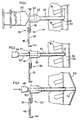
- Figure 1 of the drawings illustrates the placement of a hollow epidural needle 10 having a sharpened end 12 inserted into the back 14 of a patient between the spinous processes 16 of the vertebrae and through the ligamentum flavum 18 into the epidural space 20.
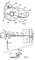
- the opposite end of needle 10 has a hub 22 having a conventional conical interior for receiving the forward extension 24 of a syringe 26 and a pivot clamp or the like connector 30 shown in more detail in Figures 10, 11 and 12.
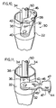
- pivot clamp 30 comprises a clamp arm 32 pivotally mounted on lateral extension or tab 36 formed adjacent the edge 38 of hub 22 by a stud 40.
- a transverse line of weakness 42 is formed in tab 36 to permit separation of tab 36 from hub 22 for reasons which will become apparent as the description proceeds.
- Clamp arm 32 has a peripheral reverse flange 44 adapted to overlap and engage flange 34 of hub 22 when clamp 32 is pivotted to the operative position shown in Figures 4, 10 and 12.
- An opening 46 on each of side edge 47 of clamp arm 32 defines slightly more than a semi-circle with a diameter substantially equal to the diameter of a cannula, to be described, whereby the clamp arm 32 can be snap-fitted over the cannula for frictional engagement, as shown most clearly in Figures 10 and 12.
- cannula 50 having a blunt distal end 52 and a blunt proximal end 49 has a diameter slightly less than the interior diameter of the needle 10 to allow placement into and coaxial movement within needle 10 such that the distal end 52 of cannula 50 can be advanced forwardly for alignment with the end 12 of needle 10 when mark 51 on the cannula is aligned with the end of needle hub 22.
- the entrance to the lumen of the cannula at the proximal end 49 is of a widened or funnel shape in order to permit the easy insertion of the catheter with a sharp internal wire protruding from it, thereby avoiding the bending of the tip of the wire at the end of the cannula.
- cannula 50 with blunt end 52 is advanced forwardly to place dura-arachnoid membrane 53 in tension and the cannula locked from axial movement by pivotting clamp arm 32 upwardly as viewed in Figures 4 - 9 of the drawings such that cannula 50 is frictionally engaged by the wall of an opening 46 when clamp arm 32 is snap-fitted thereover with reverse flange 44 engaging flange 34 of needle hub 22.
- Figure 5 illustrates a sharp stylet 55 advanced through cannula 50 to pierce the taut dura-arachnoid membrane 53 by pointed tip 58 to form a hole 60 ( Figure 6) when flanged head 57 abuts the proximal end 49 of cannula 50.
- Stylet 55 preferably would have a diameter about the same as or slightly less than the external diameter of catheter 54 to ensure a tight fit of the catheter in hole 60 to prevent the flow of cerebral-spinal fluid from the sub-arachnoid space into the epidural space.
- a catheter 54 with an interior wire 56 slidably mounted therein having an end projecting beyond the forward end of catheter 54 is inserted into cannula 50 and advanced forwardly to enter hole 60, as shown in Figure 7.
- Catheter 54 can be advanced through hole 60 in dura-arachnoid membrane 53 a desired length as indicated by mark 62 on the catheter by pushing catheter 54 with stiffening wire 56 forwardly through the dura-arachnoid membrane 53 until mark 62 on cather 54 is aligned with the proximal end of cannula hub 49, as shown in Figure 8.
- stylet 55 it may be preferred not to use stylet 55, in which case wire 56 would be sharply pointed and would extend beyond the tip of catheter 54 to pierce the dura-arachnoid membrane 53 when catheter 54 is advanced against membrane 53.
- An anaesthetic can be continuously administered to the patient through the catheter 54 by syringe 70 which is coupled either directly or by means of an extension tubing to hub 68 of catheter 54 which is fitted tightly into the end 49 of cannula 50.
- Figure 14 illustrates an embodiment of cannula in which the blunt distal end 80 has an inner bevelled, i.e. sharp, extension to pierce the dura-arachnoid membrane while maintaing the membrane taut.
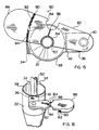
- Figure 15 and 16 illustrate another embodiment of pivot clamp 80 in which clamp arm 82, having over-centre semi-circular side openings 84 adapted to snap-fit onto cannula 50, has a transverse line of weakness formed by surface notch 86 interconnecting openings 84.
- the free end 88 of clamp arm 82 is extended to provide leverage to facilitate the breaking of clamp arm 82 to free cannula 50, when desired.
- Reverse flange 90 formed in the underside of clamp arm 82 preferably has serrations 92 adapted to engage mating serrations 94 formed in the underside of rim flange 34 to effectively lock clamp 80 against cannula 50 by a friction fit of cannula 50 in an opening 84.
- Figure 17 illustrates cannula 161 with shaft 150, splayed distal end 156, and blunt proximal end 149.
- the distal end 156 splays into one or more flexible tabs 157 which curl backwards (i.e. proximally) when in neutral or resting position.
- Sleeve 179 fits slidably over shaft 150 and has a conical exterior to fit into hub 122 of epidural needle 110, as seen in Figures 19-29.
- the distal end 156 of cannula 161 preferably is formed of resilient plastic material and is splayed radially outwardly such that the tabs are resiliently biased in an outward direction.
- Figure 17(a) is a plan view of hollow cannula shaft 150 with the distal end 156 splayed outwardly to form single tab 157.
- Figure 17(b) is a plan view of cannula shaft 150 showing another embodiment wherein the distal end of the cannula shaft 150 is splayed into four tabs 157. It will be understood that the distal end 156 of cannula 161 can be composed of one or more tabs 157 which splay radially outwardly in a curled fashion.
- Sleeve 179 slides axially over tabs 157 to hold them in a non-splayed or straightened position pointing distally, as shown in Figure 18. When in this position, tabs 157 collectively form end 152 of cannula 161. Sleeve 179 is slid to this position just prior to use.
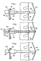
- Figure 19 illustrates the placement of hollow epidural needle 110 having a pointed end 112 inserted into the back 114 of a patient between the spinous processes 116 of the vertebrae, and through the ligamentum flavum 118 into the epidural space 120.
- the opposite end of the needle 110 has a hub 122 having a conventional conical interior for receiving a standard forward extension of a syringe and for receiving sleeve 179.
- a pivot clamp or the like connector 130 is formed integral therewith.
- Cannula 161 with sleeve 179 holding tabs 157 straight is shown in a position to enter hub 122 of epidural needle 110.
- Shaft 150 of cannula 161 has a diameter slightly less than the interior diameter of epidural needle 110 to allow placement into and forward coaxial movement within needle 110. During this forward movement, tabs 157 are held straight by needle 110 until they emerge from needle end 112 into the epidural space 120.
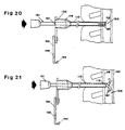
- Figure 20 shows cannula 161 advanced coaxially within epidural needle 110 so that the distal end 152 of cannula 161 is coextensive with the distal end 112 of epidural needle 110 when line 151 on the cannula is even with hub 122 of the epidural needle 110. Tabs 157 of the cannula are still held straight pointing distally inside epidural needle 110. With reference to Figure 21, cannula 161 is advanced axially distally and tabs 157 emerge from end 112 of epidural needle 110 to splay outwardly to resume their original open curled shape in epidural space 120.
- cannula 161 is advanced further so the open tabs 157 push the dura-arachnoid membrane 153 forward and place it in tension.
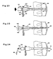
- the cannula is locked from coaxial movement by pivoting clamp 132 which is pivoted upwardly, as viewed in Figures 22 through 26, such that the cannula shaft 150 is frictionally engaged by the wall of an opening 146 when clamp arm 132 is snap-fitted thereover with reverse flange 144 engaging flange 134 of hub 122.
- Figure 23 illustrates a sharp stylet 155 advanced through cannula 161 to pierce and form a hole in the taut dura-arachnoid membrane 153 by pointed tip 158 when flanged head 159 abuts proximal end 149 of cannula 161.
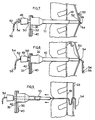
- Figure 24 shows stylet 155 removed and catheter 154 advanced through said hole a desired length by pushing catheter 154 containing stiffening wire 156 forwardly through the dura-arachnoid membrane 153 until mark 162 is aligned with the proximal end of hub 149. It may be preferred not to use stylet 155, in which case wire 156 would be sharply pointed and would extend beyond the tip of catheter 154 to pierce the dura-arachnoid membrane 153 when catheter 154 is advanced against membrane 153.
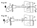
- FIG. 25 illustrates the epidural needle 110 with cannula 161 attached thereto by clamp 132 withdrawn. This results in tabs 157 of cannula 161 becoming straightened in an extended position in the tract left by needle 110 and the dura-subarachnoid membrane 153 returning to its original non-tensioned position leaving catheter 154 with wire 156 inserted the desired distance into the subarachnoid space 167.
- Figure 26 illustrates the cannula-epidural needle assembly 161-110 and wire 156 completely removed from the patient and tabs 157 of cannula 161 returned to their original splayed open position having emerged from the needle tract.
- clamp 132 is retained on cannula shaft 150 and this assembly is now slid proximally coaxially along catheter 154 to catheter hub 168.
- Clamp 132 is removed from cannula shaft 150 and cannula end 149 fits frictionally inside hub 168 at catheter 154.
- the assembled members now comprise catheter hub 168 fitted to cannula end 149 and to sleeve 179 which is fitted to needle hub 122.
- Shaft 150 of cannula 161 extends distally beyond the end 122 of needle 110, preventing the catheter 154 being cut by the sharp end 112 of needle 110.
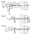
- An anaesthetic can now be continuously or intermittently administered through catheter 154 by syringe 170 or other source of an anaesthetic solution which is coupled either directly or by means of an extension tubing to hub 168 of catheter 154.
- Figure 28 illustrates an alternate application of the method and the system of the invention for the administration of a single dose spinal anaesthetic (i.e. subarachnoid anaesthetic) through a fine flexible or semi-rigid metal spinal needle.
- a single dose spinal anaesthetic i.e. subarachnoid anaesthetic
- a fine spinal needle is inserted as illustrated in Figure 28.
- FIG. 161 This figure shows spinal needle 164 inserted coaxially through cannula 161 such that when hub 160 of spinal needle 164 abuts the cannula end 149, and cannot be inserted further, the spinal needle 164 has pierced the dura-arachnoid membrane 153 and the needle 164 has entered the desired distance into the subarachnoid space 167 which contains cerebral-spinal fluid 166. The cerebral-spinal fluid 166 then flows proximally through needle 164 and forms a drop 166 in the spinal needle hub 160, confirming the correct placement of needle 164 in the subarachnoid space 167.
- a conventional syringe 170 with a standard injection tip fits into the standard interior of spinal needle hub 160 for the single administration of a spinal anaesthetic following which the entire assembly is removed.
- an engaging bracket 310 is so constructed as to have both an engaging means for both the cannula and for the epidural needle, which are thereby held in spaced relationship.
- Bracket 310 includes an engaging clip 312 of a resilient material so that if can be clipped on to needle hub 224.
- Support member 314 extends forward of engaging clip 312 and defines holding clip 316 at its forward end.
- Clip 316 includes a pair of sprung jaws 318 on clip 316 define a central aperture coaxially aligned with the aperture defined by needle engaging clip 312.
- Clip 316 includes a pair of handles 320 which when compressed toward each other, direct pivotal opening action to jaws 318.
- the bracket is attached to the hub 224 of epidural needle by means of clip 312.
- Handles 320 are then squeezed toward each other to hold jaws 318 of the clip open.
- the cannula is inserted to the desired distance and then handles 320 are released, allowing jaws 318 to close onto and engage the Cannula so that it cannot move axially in either direction.
- the cannula and needle are removed from the patient while still clamped to each other.
- the cannula is uaually not removed from the needle once they are assembled.
- the clip is removed and discarded and the proximal end of the cannula will fit tightly into the hub of the cathere, shown in Figures 13 and 27.
- needle hub 224 includes an integral tab 322 which may have a fracture line along its junction with the hub for easy break-off.
- Tab 322 includes a longitudinal groove 324 in its upper portion.
- the embodiment of Figure 31 includes a rail clip 326 which extends along a portion of the rearward end of support member 314. Bracket 310 is thereby engaged onto needle hub 224 by aligning rail clip 326 of the bracket with central groove 324, and snapping it into position.
- Tab 322 is made of a resilient plastic so that the sides defining groove 324 can be separated to accommodate clip 326.
- a central slot 328 in groove 324 receives a corresponding rim 330 on clip 326 to hold the bracket 310 in position.
- the cannula coaxially positioned within the needle is then engaged by jaws 318 of the holding clip portion 316 in the manner described above.
- a stylet is directed down through the cannula to pierce the membrane so that a spinal catheter can then be directed through the opening.
- the cannula and epidural needle are removed from the patient still clamped together.
- the clamp is disengaged from the epidural needle by breaking off tab 322 along its fracture line.
- FIG. 32a and 32b show an epidural needle 410 having an elliptical cross-section in conjunction with a cannula 412 having a similar external elliptical cross-section but small enough to fit axially through the needle when their respective cross-sections are aligned.
- Cannula 412 includes a pair of oppositely positioned lines 416 which are respectively aligned with the major cross-sectioned axis of the elliptical cannula 412 which is rounded to fit a standard syringe.
- Needle hub 424 includes a pair of oppositely positioned grooves 426 which are also so positioned as to be aligned with the major cross-sectioned axis of the elliptical needle.
- the cannula is drawn down through the needle in the manner described above.
- the major axis of cannula and needle can be easily aligned by aligning lines 416 on cannula 412 with grooves 426 on hub 424. This alignment is schematically illustrated in Figure 32b.
- the cannula When the cannula is extended through the needle to a predetermined point, such as engagement with the dura-arachnoid membrane, the cannula is rotated on its longitudinal axis approximately 90 degrees so that the major cross-sectioned axis of the cannula is aligned with the minor cross-sectioned axis of the needle thereby providing a secure wedging fit therein.
- the cannula is thereby locked in special engagement within the needle.
- the cannula can be unlocked by rotating the cannula back to its original position with respect to the needle.
- one method for controlling the placement of the catheter tip is to intrinsically bend the catheter to about 90 degrees about 2 cm. from its distal end and include a block indicator line into the catheter on the side which is convex of the bend.
- the catheter would be held straight by the cannula and the stiffening wire during insertion through the dura-arachnoid membrane.
- the stiffening wire is removed and the catheter would resume its intrinsic bend in the desired direction since it has a satisfactory degree of resiliency.
- the catheter would be inserted into and through the cannula with the black line (hence the end of the catheter) directed either cephalad (towards the patient's head) or caudad (towards the patient's feet) as desired.
- the wire should have an intrinsic bend of about 90 degrees as well. This bend could be located about 25 cm from its distal end. It was observed that when the tip of the wire contact the dura-arachnoid membrane, the wire is occasionally pushed back up the catheter. An intrinsic bend in the wire at a location which will be beyond the end of the catheter at that point in the operation will prevent it drawing back. However, the wire is sufficiently resilient that when it has to be withdrawn from the catheter, it can be pulled through without any significant additional effort. 2 It will be understood that modifications can be made in the embodiment of the invention illustrated and described herein within the scope of the invention as defined by the appended claims.
Landscapes
- Health & Medical Sciences (AREA)
- Life Sciences & Earth Sciences (AREA)
- General Health & Medical Sciences (AREA)
- Public Health (AREA)
- Engineering & Computer Science (AREA)
- Anesthesiology (AREA)
- Biomedical Technology (AREA)
- Heart & Thoracic Surgery (AREA)
- Surgery (AREA)
- Animal Behavior & Ethology (AREA)
- Veterinary Medicine (AREA)
- Pulmonology (AREA)
- Biophysics (AREA)
- Pathology (AREA)
- Nuclear Medicine, Radiotherapy & Molecular Imaging (AREA)
- Hematology (AREA)
- Medical Informatics (AREA)
- Molecular Biology (AREA)
- Infusion, Injection, And Reservoir Apparatuses (AREA)
- Media Introduction/Drainage Providing Device (AREA)
- Electrotherapy Devices (AREA)
- Acyclic And Carbocyclic Compounds In Medicinal Compositions (AREA)
Claims (12)
- Katheter-System zur Einführung eines flexiblen Katheters (54) durch den Epiduralraum (20) und die Dura-Arachnoid-Membran (53) in den subarachnoiden Raum der Wirbelsäule eines Patienten umfassend:(a) eine Hohlnadel (10; 410) mit einem zugespitzten Ende (12) zur Einführung in den Epiduralraum (20) und einem Auslaßende mit einer Nabe (22);(b) eine Kanüle (50; 412) mit einem stumpfen oder gespreizten Ende (52; 152), die so ausgebildet ist, daß sie in die Hohlnadel (10; 410) eingeführt und innerhalb der Hohlnadel (10; 410) koaxial bewegt werden kann, wobei die Kanüle (50) innerhalb der Hohlnadel (10) vorgeschoben werden kann, um das stumpfe oder gespreizte Ende (52; 152) gegen die Dura-Arachnoid-Membran (53) zu drücken, um die Dura-Arachnoid-Membran (53) unter Spannung zu setzen;(c) eine Haltevorrichtung (30-47; 82-94; 310-318; 416, 426) zum Anbringen der Kanüle (50; 412) innerhalb der Hohlnadel (10; 410) und zur Verhinderung einer koaxialen Rückwärtsbewegung in der Hohlnadel (10; 410); und(d) einen flexiblen Katheter (54) mit einem darin befindlichen Draht (56) zur Einführung durch die Kanüle (50; 412) und zum Durchstoßen der Dura-Arachnoid-Membran (53) unter Bildung eines Loches (60), wodurch das distale Ende (52) des Katheters (54) durch das Loch (60) in einer bestimmten Länge (60) durch die Dura-Arachnoid-Membran (53) in den subarachnoiden Raum eingeführt werden kann, die Kanüle (50; 412) und die Hohlnadel (10; 410) entlang des Katheters (54) zurückgezogen werden können, die Haltevorrichtung (30) entfernt und der Draht (56) aus dem Katheter (54) entfernt werden können.
- Katheter-System nach Anspruch 1, dadurch gekennzeichnet, daß der Draht (56) aus dem distalen Ende (52) des Katheters (54) herausragt und das aus dem distalen Ende (52) des Katheters (54) herausragende Ende des Drahtes (56) zugespitzt ist.
- Katheter-System nach Anspruch 1 oder 2, dadurch gekennzeichnet, daß die Haltevorrichtung (30) eine Klemme (30) umfaßt, die drehbar an einer seitlichen Verlängerung (36) der Nabe (22) der Hohlnadel (10) angebracht ist, und die Klemme (30) eine an einer Seite ausgebildete Öffnung (46) aufweist, um die Kanüle (50) reibschlüssig anzubringen und eine koaxiale Bewegung der Kanüle (50) in der Hohlnadel (19) zu blockieren.
- Kathetersystem nach Anspruch 3, dadurch gekennzeichnet, daß die seitliche Verlängerung (36) der Nabe (22) eine zur Nabe (22) benachbarte in ihr eingeformte Bruchlinie (42) aufweist, um eine Trennung der seitlichen Verlängerung (36) von der Nabe (22) zu ermöglichen.
- Kathetersystem nach einem der vorhergehenden Ansprüche, dadurch gekennzeichnet, daß die Nadel (410) einen elliptischen Querschnitt aufweist, die Nabe (424) im wesentlichen zylindrisch ist, die Kanüle (412) einen elliptischen Querschnitt aufweist, wobei die Querschnitts-Hauptachse und Nadel (410) für eine koaxiale Bewegung der Kanüle (412) innerhalb der Hohlnadel (410) ausgerichtet sind, und die Haltevorrichtung Mittel umfaßt, um die Querschnitts-Hautpachse der Kanüle (412) im Hinblick auf die Querschnitts-Hauptachse der Nadel (410; Figuren 32a, 32b) zu drehen.
- Kathetersystem nach Anspruch 1 oder 2, dadurch gekennzeichnet, daß die Haltevorrichtung eine Befestigungsklammer (310) umfaßt, die an einem Ende eine lösbare Befestigungsvorrichtung (312) zum Befestigen der Befestigungsklammer (310) an der Nadelnabe (224) besitzt, und eine Halterung (316), die sich von dieser Befestigungsvorrichtung (312) in einem bestimmten Abstand axial davon befindet, wobei die Halterung (316) mit der Kanüle mittels Feder-aktivierter Klemmen (318) befestigbar ist, und ein Paar zusammenwirkende Elemente (320) an der Halterung (316) vorhanden ist, um die Klemmen (318) zur Befestigung an der Kanüle um einen Drehpunkt zu bewegen, wodurch eine koaxiale Bewegung der Kanüle innerhalb der Hohlnadel verhindert wird.
- Kathetersystem nach einem der vorhergehenden Ansprüche, dadurch gekennzeichnet, daß die Kanüle (150; 161) ein gespreiztes distales Ende (152; 156) aufweist, das mindestens ein flexibles Endstück (157) am distalen Ende (152; 156) besitzt, und eine Schiebehülse (179) zum axialen Vorschieben über das gespreizte distale Ende (152; 156) der Kanüle (161), um das Endstück (157) gerade zu richten, um es zu ermöglichen, die Kanüle (161) in der Hohlnadel (110) anzubringen und sie darin koaxial nach vorne einzuführen, wobei die Buchse (179) in der Nabe (122) der Nadel (110) verbleibt, und sich das Ende (156) der Kanüle (161) nach Austritt aus der Hohlnadel (110) spreizt und gegen die Dura-Arachnoid-Membran (153) drückt, um die Dura-Arachnoid-Membran (153) unter Spannung zu setzen (Figuren 17-19).
- System nach Anspruch 7, dadurch gekennzeichnet, daß der Draht (156) aus dem distalen Ende (122) des Katheters (154) hinausragt und dieses aus dem distalen Ende (122) des Katheters (154) hinausragende Ende des Drahtes (156) zugespitzt ist.
- System nach Anspruch 7, dadurch gekennzeichnet, daß die Haltevorrichtung eine Klemme (132) umfaßt, die drehbar an einer seitlichen Verlängerung der Nabe (122) der Hohlnadel (110) angebracht ist, und die Klemme (132) eine an einer Seite ausgebildete Öffnung (146) aufweist, um die Kanüle (161) reibschlüssig anzubringen und eine koaxiale Bewegung der Kanüle (161) in der Hohlnadel (110) zu blockieren.
- System nach Anspruch 9, dadurch gekennzeichnet, daß die seitliche Verlängerung (136) der Nabe (122) eine zur Nabe (122) benachbarte eine in ihr eingeformte Bruchlinie (142) aufweist, um eine Trennung der seitlichen Verlängerung (136) von der Nabe (122) zu ermöglichen.
- Kathetersystem nach Anspruch 7, dadurch gekennzeichnet, daß die Hohlnadel (410) und die Kanüle (412) beide einen elliptischen Querschnitt von im wesentlichen gleicher Gestalt besitzen und die Haltevorrichtung (426) eine Einrichtung umfaßt, um die Kanüle (412) innerhalb der Hohlnadel (410) axial zu drehen, wobei die Ellipsen-Hauptachse der Kanüle (412) aus der Ausrichtung mit der Ellipsen-Hauptachse der Hohlnadel (410) herausgedreht wird.
- Kathetersystem nach Anspruch 7, dadurch gekennzeichnet, daß die Haltevorrichtung eine Befestigungsklammer (310) umfaßt, die an einem Ende eine lösbare Befestigungsvorrichtung (312) zum Befestigen der Befestigungsklammer (310) an der Nadelnabe (224) besitzt, und eine Halterung (316), die sich von dieser Befestigungsvorrichtung (312) in einem bestimmten Abstand axial davon befindet, wobei die Halterung (316) an der Kanüle (412) mittels Feder-aktivierter Klemmen (318) befestigbar ist, und ein Paar zusammenwirkende Elemente (320) an der Halterung (316) vorhanden ist, um die Klemmen (318) zur Befestigung an der Kanüle (412) um einen Drehpunkt zu bewegen, wodurch eine koaxiale Bewegung der Kanüle (412) innerhalb der Hohlnadel (410) verhindert wird.
Applications Claiming Priority (3)
| Application Number | Priority Date | Filing Date | Title |
|---|---|---|---|
| US07/357,502 US4973312A (en) | 1989-05-26 | 1989-05-26 | Method and system for inserting spinal catheters |
| US357502 | 1989-05-26 | ||
| PCT/CA1990/000169 WO1990014124A1 (en) | 1989-05-26 | 1990-05-24 | A method and system for inserting spinal catheters |
Publications (2)
| Publication Number | Publication Date |
|---|---|
| EP0428645A1 EP0428645A1 (de) | 1991-05-29 |
| EP0428645B1 true EP0428645B1 (de) | 1995-09-13 |
Family
ID=23405891
Family Applications (1)
| Application Number | Title | Priority Date | Filing Date |
|---|---|---|---|
| EP90906822A Expired - Lifetime EP0428645B1 (de) | 1989-05-26 | 1990-05-24 | Verfahren und system zur einführung eines spinal-katheters |
Country Status (9)
| Country | Link |
|---|---|
| US (2) | US4973312A (de) |
| EP (1) | EP0428645B1 (de) |
| AT (1) | ATE127698T1 (de) |
| AU (1) | AU638994B2 (de) |
| CA (1) | CA2037052C (de) |
| DE (1) | DE69022366T2 (de) |
| IE (1) | IE80142B1 (de) |
| IL (1) | IL94515A (de) |
| WO (1) | WO1990014124A1 (de) |
Families Citing this family (154)
| Publication number | Priority date | Publication date | Assignee | Title |
|---|---|---|---|---|
| US4973312A (en) * | 1989-05-26 | 1990-11-27 | Andrew Daniel E | Method and system for inserting spinal catheters |
| DE3918431C1 (de) * | 1989-06-06 | 1990-07-26 | B. Braun Melsungen Ag, 3508 Melsungen, De | |
| US5232442A (en) * | 1989-12-11 | 1993-08-03 | Brigham And Women's Hospital | Method and apparatus for inducing anesthesia |
| WO1991008785A1 (en) * | 1989-12-11 | 1991-06-27 | Brigham And Women's Hospital | Method and apparatus for inducing anesthesia |
| US5078689A (en) * | 1990-05-14 | 1992-01-07 | Keller Alan M | Device for removing body fluids |
| US5100379A (en) * | 1990-11-19 | 1992-03-31 | The Kendall Company | Microcatheter having improved tensile strength |
| US5292310A (en) * | 1990-12-27 | 1994-03-08 | Inbae Yoon | Safety needle |
| JPH0630205Y2 (ja) * | 1991-01-30 | 1994-08-17 | 方希 百合野 | 持続局所麻酔セット |
| US5183470A (en) * | 1991-03-04 | 1993-02-02 | International Medical, Inc. | Laparoscopic cholangiogram catheter and method of using same |
| US5098388A (en) * | 1991-05-02 | 1992-03-24 | Richard Kulkashi | Veress needle assembly |
| DE4128530A1 (de) * | 1991-08-28 | 1993-03-04 | Vygon Gmbh & Co Kg | Anaesthesiebesteck |
| US5205828A (en) * | 1991-10-24 | 1993-04-27 | Dan Kedem | Epidural needle location indicator assembly |
| AU651745B2 (en) * | 1991-12-13 | 1994-07-28 | Covidien Ag | Locking pneumoneedle |
| CA2088024C (en) * | 1992-02-03 | 2004-03-30 | Daniel E. Andrew | A cannula clamp |
| US5300046A (en) * | 1992-03-30 | 1994-04-05 | Symbiosis Corporation | Thoracentesis sheath catheter assembly |
| DE69305040T2 (de) * | 1992-04-09 | 1997-04-10 | Medtronic Inc | Elektrodeneinfuehreinrichtung mit mechanish oeffnendem ventil |
| US5250035A (en) * | 1992-04-20 | 1993-10-05 | Abbott Laboratories | Cannula and stylet system |
| US5354266A (en) * | 1992-07-06 | 1994-10-11 | Catheter Imaging Systems | Method of epidural surgery |
| US5857996A (en) * | 1992-07-06 | 1999-01-12 | Catheter Imaging Systems | Method of epidermal surgery |
| WO1994004212A1 (fr) * | 1992-08-18 | 1994-03-03 | Georgescu Horia Dan | Dispositif pour proteger des catheters epiduraux des bords du biseau des aiguilles |
| US5322514A (en) * | 1992-08-19 | 1994-06-21 | Sherwood Medical Company | Needle assembly with detachable wing |
| AU673703B2 (en) * | 1992-11-10 | 1996-11-21 | Seikagaku Kogyo Kabushiki Kaisha | Injector and use of the same |
| ES2160118T3 (es) * | 1993-01-07 | 2001-11-01 | Medical Innovations Corp | Sistema de cateter para gastrostomia. |
| EP0608659A1 (de) * | 1993-01-28 | 1994-08-03 | Du Kedem Technologies Ltd. | Stellungsanzeigeanordnung für Epiduralnadel |
| US5738650A (en) * | 1993-01-29 | 1998-04-14 | Becton, Dickinson And Company | Subarachnoid needle and method for administering therapeutic agents to the subarachnoid space |
| AU669026B2 (en) * | 1993-01-29 | 1996-05-23 | Becton Dickinson & Company | Catheter/needle assembly kit and method for administering therapeutic agents to the subarachnoid space |
| US5364367A (en) * | 1993-04-30 | 1994-11-15 | Minnesota Mining And Manufacturing Company | Cannula anchor |
| US5306239A (en) * | 1993-07-30 | 1994-04-26 | Simon Gurmarnik | Method of and set for spinal anesthesia |
| US5470316A (en) * | 1993-09-07 | 1995-11-28 | United States Surgical Corporation | Body tissue penetrating device having a vacuum indicator |
| US5437645A (en) * | 1993-10-08 | 1995-08-01 | United States Surgical Corporation | Surgical instrument positioning device |
| US5517846A (en) * | 1994-02-18 | 1996-05-21 | Caggiani; Carlos A. | Electronic vacuum sensor |
| GB9501424D0 (en) * | 1995-01-25 | 1995-03-15 | Carrie Len | Epidural catheter |
| US5743883A (en) * | 1995-06-07 | 1998-04-28 | Visconti; Peter L. | Thoracentesis catheter instruments having self-sealing valves |
| US6071300A (en) | 1995-09-15 | 2000-06-06 | Sub-Q Inc. | Apparatus and method for percutaneous sealing of blood vessel punctures |
| US6183497B1 (en) | 1998-05-01 | 2001-02-06 | Sub-Q, Inc. | Absorbable sponge with contrasting agent |
| US6162192A (en) | 1998-05-01 | 2000-12-19 | Sub Q, Inc. | System and method for facilitating hemostasis of blood vessel punctures with absorbable sponge |
| US5836914A (en) * | 1995-09-15 | 1998-11-17 | Becton Dickinson And Company | Method and apparatus for variably regulating the length of a combined spinal-epidural needle |
| US5782807A (en) * | 1995-10-20 | 1998-07-21 | Tfx Medical Incorporated | Releasably locking introducer devices |
| US5810788A (en) * | 1995-11-15 | 1998-09-22 | Racz; Gabor J. | R-X needle |
| USD405881S (en) | 1996-01-16 | 1999-02-16 | Catheter Imaging Systems, Inc. | Handle for steerable catheter |
| US6007531A (en) * | 1995-11-21 | 1999-12-28 | Catheter Imaging Systems, Inc. | Steerable catheter having disposable module and sterilizable handle and method of connecting same |
| USD398986S (en) | 1996-01-16 | 1998-09-29 | Catheter Imaging Systems, Inc. | Handle interface for steerable catheter |
| US5860953A (en) * | 1995-11-21 | 1999-01-19 | Catheter Imaging Systems, Inc. | Steerable catheter having disposable module and sterilizable handle and method of connecting same |
| GB9601147D0 (en) * | 1996-01-19 | 1996-03-20 | Smiths Industries Ltd | Spinal epidural needle assemblies |
| DE69719638T2 (de) * | 1996-08-16 | 2003-12-24 | Smiths Group Plc, London | Nadelanordnung |
| US6606515B1 (en) * | 1996-09-13 | 2003-08-12 | Scimed Life Systems, Inc. | Guide wire insertion and re-insertion tools and methods of use |
| US6582401B1 (en) * | 1996-09-13 | 2003-06-24 | Scimed Life Sytems, Inc. | Multi-size convertible catheter |
| US6096009A (en) | 1996-09-13 | 2000-08-01 | Boston Scientific Corporation | Guidewire and catheter locking device and method |
| US6146355A (en) * | 1996-12-30 | 2000-11-14 | Myelotec, Inc. | Steerable catheter |
| US6213974B1 (en) | 1996-12-30 | 2001-04-10 | Visionary Biomedical, Inc. | Steerable catheter having segmented tip and one-piece inlet housing, and method of fabricating same |
| US5846226A (en) * | 1997-05-12 | 1998-12-08 | Urmey; William F. | Spinal-epidural administration system |
| US6190370B1 (en) | 1997-07-25 | 2001-02-20 | Arrow International, Inc. | Devices, systems and methods for determining proper placement of epidural catheters |
| US5951518A (en) * | 1997-10-31 | 1999-09-14 | Teleflex, Incorporated | Introducing device with flared sheath end |
| US6217556B1 (en) | 1998-03-19 | 2001-04-17 | Allegiance Corporation | Drainage catheter |
| US6315753B1 (en) | 1998-05-01 | 2001-11-13 | Sub-Q, Inc. | System and method for facilitating hemostasis of blood vessel punctures with absorbable sponge |
| US20010045575A1 (en) | 1998-05-01 | 2001-11-29 | Mark Ashby | Device and method for facilitating hemostasis of a biopsy tract |
| US6129713A (en) * | 1998-08-11 | 2000-10-10 | Embol-X, Inc. | Slidable cannula and method of use |
| KR20010040761A (ko) | 1998-12-09 | 2001-05-15 | 쿡 인코포레이티드 | 중공의 만곡형 초탄성 의료용 니들 |
| US6984219B2 (en) * | 1999-09-23 | 2006-01-10 | Mark Ashby | Depth and puncture control for blood vessel hemostasis system |
| US6456874B1 (en) * | 2000-03-13 | 2002-09-24 | Arrow International Inc. | Instrument for delivery of anaesthetic drug |
| US7386341B2 (en) * | 2000-03-13 | 2008-06-10 | Arrow International, Inc. | Instrument and method for delivery of anaesthetic drugs |
| US8611993B2 (en) * | 2000-03-13 | 2013-12-17 | Arrow International, Inc. | Pre-loaded lockable stimulating catheter for delivery of anaesthetic drugs |
| US6589262B1 (en) | 2000-03-31 | 2003-07-08 | Medamicus, Inc. | Locking catheter introducing system |
| US20040015133A1 (en) * | 2000-05-31 | 2004-01-22 | Hussain Karim | Epidural apparatus |
| US20040034331A1 (en) * | 2001-02-23 | 2004-02-19 | Jason Toman | Integrated medication delivery system |
| EP1379291A4 (de) | 2001-02-23 | 2008-09-24 | Stryker Instr | Integriertes medikamentenabgabesystem |
| US7087040B2 (en) | 2001-02-28 | 2006-08-08 | Rex Medical, L.P. | Apparatus for delivering ablation fluid to treat lesions |
| US6989004B2 (en) | 2001-02-28 | 2006-01-24 | Rex Medical, L.P. | Apparatus for delivering ablation fluid to treat lesions |
| DE60208780T2 (de) * | 2001-02-28 | 2006-08-10 | Rex Medical, L.P. | Vorrichtung zur applikation von ablationsfluid zur behandlung von läsionen |
| US8187625B2 (en) | 2001-03-12 | 2012-05-29 | Boston Scientific Scimed, Inc. | Cross-linked gelatin composition comprising a wetting agent |
| US7008440B2 (en) * | 2001-11-08 | 2006-03-07 | Sub-Q, Inc. | System and method for delivering hemostasis promoting material to a blood vessel puncture site by fluid pressure |
| US7029489B1 (en) * | 2001-05-18 | 2006-04-18 | Sub-Q, Inc. | System and method for delivering hemostasis promoting material to a blood vessel puncture site |
| US7022109B1 (en) | 2001-07-09 | 2006-04-04 | Ditto Deborah L | Pain abatement catheter system |
| US20030093105A1 (en) * | 2001-07-13 | 2003-05-15 | Scimed Life Systems, Inc. | Guide catheter for introduction into the subarachnoid space and methods of use thereof |
| US7150737B2 (en) | 2001-07-13 | 2006-12-19 | Sci/Med Life Systems, Inc. | Methods and apparatuses for navigating the subarachnoid space |
| US7011647B2 (en) * | 2001-07-13 | 2006-03-14 | Scimed Life Systems, Inc. | Introducer sheath |
| US7455666B2 (en) | 2001-07-13 | 2008-11-25 | Board Of Regents, The University Of Texas System | Methods and apparatuses for navigating the subarachnoid space |
| US7037322B1 (en) * | 2001-11-08 | 2006-05-02 | Sub-Q, Inc. | System and method for delivering hemostasis promoting material to a blood vessel puncture with a staging tube |
| US7044936B2 (en) | 2002-08-21 | 2006-05-16 | Arrow International Inc. | Catheter connector with pivot lever spring latch |
| AU2003276903A1 (en) | 2002-09-20 | 2004-05-04 | Flowmedica, Inc. | Method and apparatus for selective material delivery via an intra-renal catheter |
| EP1585572A4 (de) | 2002-09-20 | 2010-02-24 | Flowmedica Inc | Verfahren und vorrichtung zur intraaortalen wirkstoffabgabe an eine gefässverzweigung |
| US7993325B2 (en) * | 2002-09-20 | 2011-08-09 | Angio Dynamics, Inc. | Renal infusion systems and methods |
| US7465304B1 (en) | 2003-04-14 | 2008-12-16 | Spine Design, Inc. | Anterior cervical facet discectomy surgery kit and method for its use |
| EP1635736A2 (de) | 2003-06-05 | 2006-03-22 | FlowMedica, Inc. | Systeme und verfahren zur durchführung von bilateralen interventionen oder diagnose in verzweigten körperlumen |
| US20040254433A1 (en) * | 2003-06-12 | 2004-12-16 | Bandis Steven D. | Sensor introducer system, apparatus and method |
| DE20309481U1 (de) * | 2003-06-20 | 2003-09-04 | stryker Trauma GmbH, 24232 Schönkirchen | Vorrichtung zum lagerichtigen Einbringen eines Führungsdrahtes für ein Bohrwerkzeug in einen Knochen |
| US20050090801A1 (en) * | 2003-10-27 | 2005-04-28 | Racz N. S. | Safety spinal catheter |
| US7875043B1 (en) | 2003-12-09 | 2011-01-25 | Sub-Q, Inc. | Cinching loop |
| WO2005091910A2 (en) | 2004-03-04 | 2005-10-06 | Flowmedica, Inc. | Sheath for use in peripheral interventions |
| US7854731B2 (en) | 2004-03-18 | 2010-12-21 | C. R. Bard, Inc. | Valved catheter |
| US7578803B2 (en) | 2004-03-18 | 2009-08-25 | C. R. Bard, Inc. | Multifunction adaptor for an open-ended catheter |
| US7094218B2 (en) | 2004-03-18 | 2006-08-22 | C. R. Bard, Inc. | Valved catheter |
| US7594911B2 (en) | 2004-03-18 | 2009-09-29 | C. R. Bard, Inc. | Connector system for a proximally trimmable catheter |
| US7594910B2 (en) | 2004-03-18 | 2009-09-29 | C. R. Bard, Inc. | Catheter connector |
| US8083728B2 (en) | 2004-03-18 | 2011-12-27 | C. R. Bard, Inc. | Multifunction adaptor for an open-ended catheter |
| US7377915B2 (en) | 2004-04-01 | 2008-05-27 | C. R. Bard, Inc. | Catheter connector system |
| CN1946451A (zh) | 2004-04-30 | 2007-04-11 | C.R.巴德有限公司 | 静脉插管的阀式护套导入器 |
| WO2005112980A2 (en) * | 2004-05-14 | 2005-12-01 | Flowmedica, Inc. | Bi-lateral local renal delivery for treating congestive heart failure and for bnp therapy |
| WO2006019814A2 (en) * | 2004-07-15 | 2006-02-23 | Boston Scientific Limited | Tissue tract lancet |
| US9216015B2 (en) | 2004-10-28 | 2015-12-22 | Vycor Medical, Inc. | Apparatus and methods for performing brain surgery |
| US8926564B2 (en) | 2004-11-29 | 2015-01-06 | C. R. Bard, Inc. | Catheter introducer including a valve and valve actuator |
| US8932260B2 (en) | 2004-11-29 | 2015-01-13 | C. R. Bard, Inc. | Reduced-friction catheter introducer and method of manufacturing and using the same |
| US9597483B2 (en) | 2004-11-29 | 2017-03-21 | C. R. Bard, Inc. | Reduced-friction catheter introducer and method of manufacturing and using the same |
| US8403890B2 (en) | 2004-11-29 | 2013-03-26 | C. R. Bard, Inc. | Reduced friction catheter introducer and method of manufacturing and using the same |
| WO2006083744A1 (en) * | 2005-01-31 | 2006-08-10 | Medtronic, Inc. | Anchoring of a medical device component adjacent a dura of the brain or spinal cord |
| CN1672649A (zh) * | 2005-04-16 | 2005-09-28 | 何明利 | 一种脑脊液穿刺引流器 |
| US20060287583A1 (en) | 2005-06-17 | 2006-12-21 | Pool Cover Corporation | Surgical access instruments for use with delicate tissues |
| US7875019B2 (en) | 2005-06-20 | 2011-01-25 | C. R. Bard, Inc. | Connection system for multi-lumen catheter |
| CA2613323A1 (en) * | 2005-06-22 | 2007-01-04 | Vycor Medical, Inc. | Surgical access instruments for use with spinal or orthopedic surgery |
| WO2007022599A1 (en) * | 2005-08-26 | 2007-03-01 | Novodural Pty Ltd | Improvements relating to epidural administration systems |
| US7771401B2 (en) * | 2006-06-08 | 2010-08-10 | Angiodynamics, Inc. | Selective renal cannulation and infusion systems and methods |
| US10850235B2 (en) | 2006-10-09 | 2020-12-01 | Minnetronix, Inc. | Method for filtering cerebrospinal fluid (CSF) including monitoring CSF flow |
| US10632237B2 (en) | 2006-10-09 | 2020-04-28 | Minnetronix, Inc. | Tangential flow filter system for the filtration of materials from biologic fluids |
| WO2008105959A2 (en) | 2006-10-09 | 2008-09-04 | Neurofluidics, Inc. | Cerebrospinal fluid purification system |
| US8372000B2 (en) | 2007-01-03 | 2013-02-12 | Boston Scientific Scimed, Inc. | Method and apparatus for biliary access and stone retrieval |
| US20080171984A1 (en) * | 2007-01-11 | 2008-07-17 | Miller Peter C | Cannula driver and system |
| US20080183192A1 (en) | 2007-01-26 | 2008-07-31 | Laurimed Llc | Contralateral insertion method to treat herniation with device using visualization components |
| US20080188826A1 (en) * | 2007-02-01 | 2008-08-07 | Laurimed, Llc | Methods and devices for treating tissue |
| US8480570B2 (en) | 2007-02-12 | 2013-07-09 | Boston Scientific Scimed, Inc. | Endoscope cap |
| US8795316B2 (en) * | 2007-04-25 | 2014-08-05 | DePuy Syntheses Products, LLC | Implantable medical device delivery system with a frangible portion and methods of making and using the same |
| CN101903062A (zh) * | 2007-10-19 | 2010-12-01 | C·R·巴德股份有限公司 | 具有成形的远侧区域的导引装置 |
| BRPI0907166B8 (pt) * | 2008-01-14 | 2021-06-22 | Custom Medical Applications Inc | elemento de fluxo para uso com agulhas de sistema nervoso flexíveis, conjunto de agulha espinal flexível e processo para produzir um elemento de fluxo |
| US8287496B2 (en) | 2008-01-17 | 2012-10-16 | Custom Medical Applications, Inc. | Flow elements for use with flexible spinal needles, needle assemblies and methods therefor |
| US8343041B2 (en) | 2008-05-19 | 2013-01-01 | Boston Scientific Scimed, Inc. | Integrated locking device with passive sealing |
| US8388521B2 (en) | 2008-05-19 | 2013-03-05 | Boston Scientific Scimed, Inc. | Integrated locking device with active sealing |
| USD597667S1 (en) | 2008-03-20 | 2009-08-04 | Custom Medical Applications, Inc. | Flexible spinal needle |
| WO2009124192A1 (en) | 2008-04-02 | 2009-10-08 | Laurimed, Llc | Methods and devices for delivering injections |
| WO2010151825A1 (en) | 2009-06-26 | 2010-12-29 | C. R. Bard, Inc. | Proximally trimmable catheter including pre-attached bifurcation and related methods |
| EP2485638B1 (de) | 2009-10-07 | 2016-11-30 | Endophys Holdings, LLC | Medizinische druckerfassungsvorrichtungen |
| CA2804200C (en) | 2010-06-30 | 2017-06-13 | Laurimed, Llc | Devices and methods for cutting and evacuating tissue |
| US8685052B2 (en) | 2010-06-30 | 2014-04-01 | Laurimed, Llc | Devices and methods for cutting tissue |
| US8696620B2 (en) * | 2010-07-30 | 2014-04-15 | St. Jude Medical, Atrial Fibrillation Division, Inc. | Catheter with a mechanism for omni-directional deflection of a catheter shaft |
| US9308001B2 (en) * | 2011-03-18 | 2016-04-12 | Carlos Andres Rodriguez | Vertebral cavitation surgical tool |
| EP2617370B1 (de) | 2012-01-19 | 2017-12-20 | Stryker European Holdings I, LLC | Hülse, insbesondere für suprapatellare Chirurgie |
| US9770289B2 (en) | 2012-02-10 | 2017-09-26 | Myromed, Llc | Vacuum powered rotary devices and methods |
| WO2015047989A1 (en) * | 2013-09-24 | 2015-04-02 | Merit Medical Systems, Inc. | Surgical implement guide assembly and methods |
| US8815099B1 (en) | 2014-01-21 | 2014-08-26 | Laurimed, Llc | Devices and methods for filtering and/or collecting tissue |
| US9855402B2 (en) | 2014-02-15 | 2018-01-02 | Rex Medical, L.P. | Apparatus for delivering fluid to treat renal hypertension |
| EP3142541A4 (de) | 2014-05-13 | 2017-04-26 | Vycor Medical, Inc. | Leitsystemhalterungen für chirurgische einführer |
| US10272227B2 (en) | 2014-11-07 | 2019-04-30 | C. R. Bard, Inc. | Connection system for tunneled catheters |
| ES2595486B1 (es) * | 2015-05-28 | 2017-10-04 | Fundacion Para La Investigación Biomédica Del Hospital 12 De Octubre | Aplicador de catéteres y catéter que incorpora dicho aplicador |
| US11147540B2 (en) | 2015-07-01 | 2021-10-19 | Minnetronix, Inc. | Introducer sheath and puncture tool for the introduction and placement of a catheter in tissue |
| CA2994669C (en) | 2015-08-05 | 2020-11-17 | Minnetronix, Inc. | Tangential flow filter system for the filtration of materials from biologic fluids |
| EP3383448B1 (de) | 2015-12-04 | 2021-01-27 | Minnetronix Inc. | Systeme zur konditionierung von liquor |
| US12178469B2 (en) | 2016-11-07 | 2024-12-31 | Vycor Medical Inc. | Surgical introducer with guidance system receptacle |
| US10376258B2 (en) | 2016-11-07 | 2019-08-13 | Vycor Medical, Inc. | Surgical introducer with guidance system receptacle |
| US10543016B2 (en) | 2016-11-07 | 2020-01-28 | Vycor Medical, Inc. | Surgical introducer with guidance system receptacle |
| JP6999708B2 (ja) | 2017-08-11 | 2022-01-19 | ボストン サイエンティフィック サイムド,インコーポレイテッド | 内視鏡用生検キャップ |
| EP3672682B1 (de) | 2017-08-23 | 2024-04-03 | C. R. Bard, Inc. | Katheteranordnungen und verfahren dafür |
| US11129728B1 (en) | 2018-10-03 | 2021-09-28 | Guillermo Molina | Surgically implantable joint spacer |
| ES2835049B2 (es) * | 2019-12-18 | 2022-10-21 | Fundacion Para La Investig Biomedica Del Hospital 12 De Octubre | Aplicador para cateter y metodo de uso |
| US11684485B1 (en) | 2020-02-04 | 2023-06-27 | Guillermo Molina | Surgically implantable joint spacer |
| JP2025522604A (ja) | 2022-07-06 | 2025-07-15 | ビコール メディカル,インコーポレイティド | 拡張可能外科用アクセスポート |
| WO2024197367A1 (pt) * | 2023-03-30 | 2024-10-03 | Janotti Cavalcante Ricardo | Seringa de cateterização |
Family Cites Families (14)
| Publication number | Priority date | Publication date | Assignee | Title |
|---|---|---|---|---|
| DE265972C (de) * | ||||
| GB904635A (en) * | 1960-03-28 | 1962-08-29 | Roderick Sutherland Ross | Hypodermic needle |
| US3506007A (en) * | 1967-07-24 | 1970-04-14 | Henkin Melvyn Lane | Catheter-needle |
| US4013080A (en) * | 1974-10-03 | 1977-03-22 | Froning Edward C | Cannula connector and direction indicator means for injection system |
| US4191186A (en) * | 1977-12-12 | 1980-03-04 | Abbott Laboratories | Removable digit engageable means for separating a catheter and stylet |
| US4192305A (en) * | 1978-08-21 | 1980-03-11 | Abbott Laboratories | Catheter placement assembly having axial and rotational alignment means |
| US4362156A (en) * | 1979-04-18 | 1982-12-07 | Riverain Corporation | Intravenous infusion assembly |
| US4576589A (en) * | 1983-03-28 | 1986-03-18 | Codman & Shurtleff, Inc. | Trocar |
| GB8506627D0 (en) * | 1985-03-14 | 1985-04-17 | Critikon Ltd | Catheter |
| US4642101A (en) * | 1985-05-16 | 1987-02-10 | Krolikowski F John | Non-traumatic bulbous catheter |
| FR2622117B1 (fr) * | 1987-10-27 | 1997-01-31 | Cordis Sa | Introducteur de catheter a canule et stylet |
| DE8811408U1 (de) * | 1988-09-09 | 1988-12-01 | B. Braun Melsungen Ag, 3508 Melsungen | Kathetervorrichtung für die Spinalanästhesie |
| US4973312A (en) * | 1989-05-26 | 1990-11-27 | Andrew Daniel E | Method and system for inserting spinal catheters |
| US5064414A (en) * | 1989-07-28 | 1991-11-12 | Angeion Corporation | Locking clip with sheath and dilator |
-
1989
- 1989-05-26 US US07/357,502 patent/US4973312A/en not_active Expired - Lifetime
-
1990
- 1990-05-24 WO PCT/CA1990/000169 patent/WO1990014124A1/en not_active Ceased
- 1990-05-24 AU AU56365/90A patent/AU638994B2/en not_active Ceased
- 1990-05-24 AT AT90906822T patent/ATE127698T1/de active
- 1990-05-24 CA CA002037052A patent/CA2037052C/en not_active Expired - Fee Related
- 1990-05-24 US US07/656,153 patent/US5160323A/en not_active Expired - Fee Related
- 1990-05-24 EP EP90906822A patent/EP0428645B1/de not_active Expired - Lifetime
- 1990-05-24 DE DE69022366T patent/DE69022366T2/de not_active Expired - Fee Related
- 1990-05-25 IL IL9451590A patent/IL94515A/en not_active IP Right Cessation
- 1990-05-25 IE IE190490A patent/IE80142B1/en not_active IP Right Cessation
Also Published As
| Publication number | Publication date |
|---|---|
| DE69022366D1 (de) | 1995-10-19 |
| ATE127698T1 (de) | 1995-09-15 |
| AU5636590A (en) | 1990-12-18 |
| DE69022366T2 (de) | 1996-02-29 |
| CA2037052A1 (en) | 1991-11-25 |
| IE901904L (en) | 1990-11-26 |
| CA2037052C (en) | 1995-08-01 |
| US4973312A (en) | 1990-11-27 |
| IE80142B1 (en) | 1998-06-03 |
| WO1990014124A1 (en) | 1990-11-29 |
| IL94515A (en) | 1994-08-26 |
| US5160323A (en) | 1992-11-03 |
| IE901904A1 (en) | 1991-02-13 |
| AU638994B2 (en) | 1993-07-15 |
| EP0428645A1 (de) | 1991-05-29 |
| IL94515A0 (en) | 1991-03-10 |
Similar Documents
| Publication | Publication Date | Title |
|---|---|---|
| US5160323A (en) | Method and system for inserting spinal catheters | |
| US5232442A (en) | Method and apparatus for inducing anesthesia | |
| US5135525A (en) | Catheter set for continuous spinal anaesthesia | |
| US6004293A (en) | Slotted regional anesthesia needle | |
| US5304141A (en) | Method and apparatus for inducing anesthesia | |
| US4940458A (en) | Epidural needle placement system | |
| US5725504A (en) | Spinal epidural needle assemblies | |
| EP1301131B1 (de) | Epiduralnadel mit sekundärabschrägung | |
| US5106376A (en) | Anaesthesia set | |
| US4518383A (en) | Instrument and method for epidural and spinal anaesthesia | |
| US20020177864A1 (en) | Vascular needle | |
| US5830188A (en) | Curved cannula for continuous spinal anesthesia | |
| US4721506A (en) | Flat-inclined tip needle | |
| US5250035A (en) | Cannula and stylet system | |
| US6554809B2 (en) | Epidural catheter needle | |
| EP1113837B1 (de) | Kathetereinführvorrichtung mit Klemmflügeln | |
| EP0555043B1 (de) | Klemmvorrichtung | |
| JPH10305101A (ja) | 複合型硬麻/脊麻針装置 | |
| JPH0857052A (ja) | 複合脊麻針−硬麻針の伸長長さの調節装置及びその調節方法 | |
| JP2006506202A (ja) | 局所部位麻酔用器具と該器具のカニューレの製造方法 | |
| US8394063B2 (en) | Medical instrument | |
| CA1326194C (en) | Method and system for inserting spinal catheters | |
| JP2001238947A (ja) | 穿刺具および穿刺具セット | |
| EP0900546A1 (de) | Führungsnadel - Kathetervorrichtung für medizinische oder veterinäre Anwendung | |
| GB2377889A (en) | Subcutaneous tunnelling |
Legal Events
| Date | Code | Title | Description |
|---|---|---|---|
| PUAI | Public reference made under article 153(3) epc to a published international application that has entered the european phase |
Free format text: ORIGINAL CODE: 0009012 |
|
| 17P | Request for examination filed |
Effective date: 19910315 |
|
| AK | Designated contracting states |
Kind code of ref document: A1 Designated state(s): AT BE CH DE DK ES FR GB IT LI LU NL SE |
|
| 17Q | First examination report despatched |
Effective date: 19931129 |
|
| GRAA | (expected) grant |
Free format text: ORIGINAL CODE: 0009210 |
|
| AK | Designated contracting states |
Kind code of ref document: B1 Designated state(s): AT BE CH DE DK ES FR GB IT LI LU NL SE |
|
| PG25 | Lapsed in a contracting state [announced via postgrant information from national office to epo] |
Ref country code: IT Free format text: LAPSE BECAUSE OF FAILURE TO SUBMIT A TRANSLATION OF THE DESCRIPTION OR TO PAY THE FEE WITHIN THE PRE;WARNING: LAPSES OF ITALIAN PATENTS WITH EFFECTIVE DATE BEFORE 2007 MAY HAVE OCCURRED AT ANY TIME BEFORE 2007. THE CORRECT EFFECTIVE DATE MAY BE DIFFERENT FROM THE ONE RECORDED.SCRIBED TIME-LIMIT Effective date: 19950913 Ref country code: BE Effective date: 19950913 Ref country code: NL Free format text: LAPSE BECAUSE OF FAILURE TO SUBMIT A TRANSLATION OF THE DESCRIPTION OR TO PAY THE FEE WITHIN THE PRESCRIBED TIME-LIMIT Effective date: 19950913 Ref country code: LI Effective date: 19950913 Ref country code: AT Effective date: 19950913 Ref country code: ES Free format text: THE PATENT HAS BEEN ANNULLED BY A DECISION OF A NATIONAL AUTHORITY Effective date: 19950913 Ref country code: CH Effective date: 19950913 Ref country code: DK Effective date: 19950913 |
|
| REF | Corresponds to: |
Ref document number: 127698 Country of ref document: AT Date of ref document: 19950915 Kind code of ref document: T |
|
| REF | Corresponds to: |
Ref document number: 69022366 Country of ref document: DE Date of ref document: 19951019 |
|
| ET | Fr: translation filed | ||
| REG | Reference to a national code |
Ref country code: CH Ref legal event code: PL |
|
| NLV1 | Nl: lapsed or annulled due to failure to fulfill the requirements of art. 29p and 29m of the patents act | ||
| PG25 | Lapsed in a contracting state [announced via postgrant information from national office to epo] |
Ref country code: SE Effective date: 19960525 |
|
| PG25 | Lapsed in a contracting state [announced via postgrant information from national office to epo] |
Ref country code: LU Free format text: LAPSE BECAUSE OF NON-PAYMENT OF DUE FEES Effective date: 19960531 |
|
| PLBE | No opposition filed within time limit |
Free format text: ORIGINAL CODE: 0009261 |
|
| STAA | Information on the status of an ep patent application or granted ep patent |
Free format text: STATUS: NO OPPOSITION FILED WITHIN TIME LIMIT |
|
| 26N | No opposition filed | ||
| EUG | Se: european patent has lapsed |
Ref document number: 90906822.3 |
|
| PGFP | Annual fee paid to national office [announced via postgrant information from national office to epo] |
Ref country code: GB Payment date: 19990324 Year of fee payment: 10 |
|
| PGFP | Annual fee paid to national office [announced via postgrant information from national office to epo] |
Ref country code: DE Payment date: 19990329 Year of fee payment: 10 |
|
| PGFP | Annual fee paid to national office [announced via postgrant information from national office to epo] |
Ref country code: FR Payment date: 19990528 Year of fee payment: 10 |
|
| PG25 | Lapsed in a contracting state [announced via postgrant information from national office to epo] |
Ref country code: GB Free format text: LAPSE BECAUSE OF NON-PAYMENT OF DUE FEES Effective date: 20000524 |
|
| GBPC | Gb: european patent ceased through non-payment of renewal fee |
Effective date: 20000524 |
|
| PG25 | Lapsed in a contracting state [announced via postgrant information from national office to epo] |
Ref country code: FR Free format text: LAPSE BECAUSE OF NON-PAYMENT OF DUE FEES Effective date: 20010131 |
|
| PG25 | Lapsed in a contracting state [announced via postgrant information from national office to epo] |
Ref country code: DE Free format text: LAPSE BECAUSE OF NON-PAYMENT OF DUE FEES Effective date: 20010301 |
|
| REG | Reference to a national code |
Ref country code: FR Ref legal event code: ST |