EP0428726B1 - Luft-depolarisierungsbatterie - Google Patents
Luft-depolarisierungsbatterie Download PDFInfo
- Publication number
- EP0428726B1 EP0428726B1 EP89908869A EP89908869A EP0428726B1 EP 0428726 B1 EP0428726 B1 EP 0428726B1 EP 89908869 A EP89908869 A EP 89908869A EP 89908869 A EP89908869 A EP 89908869A EP 0428726 B1 EP0428726 B1 EP 0428726B1
- Authority
- EP
- European Patent Office
- Prior art keywords
- cathode
- anode
- air cell
- liquid
- separator
- Prior art date
- Legal status (The legal status is an assumption and is not a legal conclusion. Google has not performed a legal analysis and makes no representation as to the accuracy of the status listed.)
- Expired - Lifetime
Links
- 239000007788 liquid Substances 0.000 claims description 13
- 239000003792 electrolyte Substances 0.000 claims description 7
- 239000005871 repellent Substances 0.000 claims description 4
- OKTJSMMVPCPJKN-UHFFFAOYSA-N Carbon Chemical compound [C] OKTJSMMVPCPJKN-UHFFFAOYSA-N 0.000 description 19
- 239000003208 petroleum Substances 0.000 description 10
- 239000007789 gas Substances 0.000 description 8
- 239000011521 glass Substances 0.000 description 8
- 238000006243 chemical reaction Methods 0.000 description 7
- 229910052799 carbon Inorganic materials 0.000 description 6
- 239000000463 material Substances 0.000 description 6
- 230000005540 biological transmission Effects 0.000 description 5
- PXHVJJICTQNCMI-UHFFFAOYSA-N Nickel Chemical compound [Ni] PXHVJJICTQNCMI-UHFFFAOYSA-N 0.000 description 4
- FAPWRFPIFSIZLT-UHFFFAOYSA-M Sodium chloride Chemical compound [Na+].[Cl-] FAPWRFPIFSIZLT-UHFFFAOYSA-M 0.000 description 4
- 230000003247 decreasing effect Effects 0.000 description 4
- 238000004519 manufacturing process Methods 0.000 description 4
- XLYOFNOQVPJJNP-UHFFFAOYSA-N water Substances O XLYOFNOQVPJJNP-UHFFFAOYSA-N 0.000 description 4
- 238000009792 diffusion process Methods 0.000 description 3
- 229910002804 graphite Inorganic materials 0.000 description 3
- 239000010439 graphite Substances 0.000 description 3
- 239000011777 magnesium Substances 0.000 description 3
- 229910000861 Mg alloy Inorganic materials 0.000 description 2
- 229910003307 Ni-Cd Inorganic materials 0.000 description 2
- 229910045601 alloy Inorganic materials 0.000 description 2
- 239000000956 alloy Substances 0.000 description 2
- QVGXLLKOCUKJST-UHFFFAOYSA-N atomic oxygen Chemical compound [O] QVGXLLKOCUKJST-UHFFFAOYSA-N 0.000 description 2
- 239000003054 catalyst Substances 0.000 description 2
- 238000005259 measurement Methods 0.000 description 2
- 229910052751 metal Inorganic materials 0.000 description 2
- 239000002184 metal Substances 0.000 description 2
- 238000000034 method Methods 0.000 description 2
- 229910052759 nickel Inorganic materials 0.000 description 2
- 229910052760 oxygen Inorganic materials 0.000 description 2
- 239000001301 oxygen Substances 0.000 description 2
- -1 polytetrafluoroethylene Polymers 0.000 description 2
- 229920001343 polytetrafluoroethylene Polymers 0.000 description 2
- 239000004810 polytetrafluoroethylene Substances 0.000 description 2
- 230000002940 repellent Effects 0.000 description 2
- 239000013535 sea water Substances 0.000 description 2
- 239000011780 sodium chloride Substances 0.000 description 2
- 229910000838 Al alloy Inorganic materials 0.000 description 1
- RYGMFSIKBFXOCR-UHFFFAOYSA-N Copper Chemical compound [Cu] RYGMFSIKBFXOCR-UHFFFAOYSA-N 0.000 description 1
- FYYHWMGAXLPEAU-UHFFFAOYSA-N Magnesium Chemical compound [Mg] FYYHWMGAXLPEAU-UHFFFAOYSA-N 0.000 description 1
- PWHULOQIROXLJO-UHFFFAOYSA-N Manganese Chemical compound [Mn] PWHULOQIROXLJO-UHFFFAOYSA-N 0.000 description 1
- 229910019440 Mg(OH) Inorganic materials 0.000 description 1
- 229910001297 Zn alloy Inorganic materials 0.000 description 1
- 239000011358 absorbing material Substances 0.000 description 1
- 229910052793 cadmium Inorganic materials 0.000 description 1
- BDOSMKKIYDKNTQ-UHFFFAOYSA-N cadmium atom Chemical compound [Cd] BDOSMKKIYDKNTQ-UHFFFAOYSA-N 0.000 description 1
- OJIJEKBXJYRIBZ-UHFFFAOYSA-N cadmium nickel Chemical compound [Ni].[Cd] OJIJEKBXJYRIBZ-UHFFFAOYSA-N 0.000 description 1
- 238000010276 construction Methods 0.000 description 1
- 229910052802 copper Inorganic materials 0.000 description 1
- 239000010949 copper Substances 0.000 description 1
- 239000006185 dispersion Substances 0.000 description 1
- 230000000694 effects Effects 0.000 description 1
- 239000008151 electrolyte solution Substances 0.000 description 1
- 230000008020 evaporation Effects 0.000 description 1
- 238000001704 evaporation Methods 0.000 description 1
- 229910052749 magnesium Inorganic materials 0.000 description 1
- 229910052748 manganese Inorganic materials 0.000 description 1
- 239000011572 manganese Substances 0.000 description 1
- 239000000203 mixture Substances 0.000 description 1
- 239000011148 porous material Substances 0.000 description 1
- 239000000843 powder Substances 0.000 description 1
- 238000010248 power generation Methods 0.000 description 1
- 150000003839 salts Chemical class 0.000 description 1
- 238000007086 side reaction Methods 0.000 description 1
- 239000000243 solution Substances 0.000 description 1
- 231100000167 toxic agent Toxicity 0.000 description 1
- 239000003440 toxic substance Substances 0.000 description 1
Images


Classifications
-
- H—ELECTRICITY
- H01—ELECTRIC ELEMENTS
- H01M—PROCESSES OR MEANS, e.g. BATTERIES, FOR THE DIRECT CONVERSION OF CHEMICAL ENERGY INTO ELECTRICAL ENERGY
- H01M12/00—Hybrid cells; Manufacture thereof
- H01M12/04—Hybrid cells; Manufacture thereof composed of a half-cell of the fuel-cell type and of a half-cell of the primary-cell type
- H01M12/06—Hybrid cells; Manufacture thereof composed of a half-cell of the fuel-cell type and of a half-cell of the primary-cell type with one metallic and one gaseous electrode
Definitions
- the present invention relates to an air cell.
- one or more cells to be mounted In order to drive a motor mounted on a model airplane, one or more cells to be mounted must be compact in size and light in weight so that generally nickel-cadmium cells are used.
- the conventional cells have a further problem that not only for model helicopters mentioned above but also for driving power supplies which must supply high power, the demands for higher power per unit weight and a longer service life cannot be satisfied.
- An object of the present invention is to provide an air cell which is compact in size and light in weight yet is capable of supplying a high output.
- an air cell comprising:
- the current collector is so disposed between the cathode and the anode that it contacts the cathode, so that the air cell can be made compact in size and light in weight, has a low degree of internal resistance, and accordingly is advantageous to the generation of a high current.
- the cathode may either be constructed by assembling a plurality of cathode sections or has at least one through hole so that the air cell is compact in size and light in weight yet is capable of producing a high output.
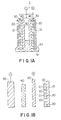
- Fig. 1A is a schematic longitudinal sectional view illustrating the first embodiment of the invention.
- Fig. 1B is an exploded view of the right half of the air cell 1 shown in Fig. 1A, illustrating its component parts separated from each other.
- the air cell, 1 of the first embodiment of the present invention has a glass paper 10, the cathode 20, a current collector 30, a separator 40, an anode 50 and a liquid storage 60 storing therein KCl liquid 61.
- the glass paper 10 is a mounting plate for the cathode 20 and is water repellent.
- the cathode 20 is a film mainly consisting of petroleum graphite powder.
- the cathode 20 is caused to be in intimate contact with the surface on the side of the anode 50 of the glass paper 10 and is divided into a plurality of sections.
- the current collector 30 is in the form of a wire net or a mesh which is fabricated with a metal such as nickel, copper or the like and has a mesh range of from 200 to 300 mesh, so that the air and liquid may pass through the current collector 30. It is disposed between the anode 50 and the cathode 20 and is in intimate contact with the cathode 20.
- the separator 40 is made of a water absorbing material such as glass paper which has not been subjected to a water repellent treatment. It electrically isolates the current collector 30 from the anode 50 and absorbs KCl or NaCl liquid (electrolyte) 61 to be caused by a capillary phenomenon, so that the anode 50 and the cathode 20 are wetted.
- a sheet of paper can be used for the separator 40.
- the anode 50 is made of a magnesium alloy, a zinc alloy, an aluminum alloy or the like. Only one alloy may be used to fabricate the anode 50, or the anode 50 may also be made of a plurality of alloys.
- the cathode 20 is divided into a plurality of cathode sections so that the cathode 20 has flat surface portions 21 and edges 22 which are in contact with the current collector 30.
- the cathode 20 and the adjacent projections 22 are spaced apart from each other.
- the cathode 20 when, instead of fabricating the cathode 20 from a single sheet, the cathode 20 consists of a plurality divided sections, the quantity of the transmitted oxygen becomes large. As a result, the reaction at the cathode which contributes to the power generation is accelerated, so that the generated power is increased.
- the cathode 20 when, instead of fabricating the cathode 20 with a plurality of sectioned cathodes, the cathode 20 is made of a single flat sheet and is formed with at least one aperture or through hole, the generated power per unit weight is increased as described above.
- the current collector 30 is placed in intimate contact with the cathode 20 on the side of the anode 50, so that the electrons generated in the anode 50 need not pass through the cathode 20. As a result, the internal voltage drop in the air cell 1 is less.
- anodes are disposed at the center portion of an air cell; cathodes are disposed outwardly of the anodes; and a wire net made of a metal such as nickel is disposed outwardly of the cathodes and used as a current collector.
- the above-described reactions occur at the cathode side of the anode, or the inner surface of the anode, so that when the electrons flow from the current collectors to the cathodes and further flow through the cathodes, they encounter the electric resistance of the order of 0.1 ⁇ .
- the voltage drop becomes 1 V.
- the current collector 30 is placed in intimate contact with the surface on the side of the anode 50 side of the cathode 20, so that the current collector 30 is disposed at the portion at which the above-mentioned reactions occur, and consequently the electrons generated at the anode 50 can flow directly to the reaction portion without passing through the cathode 20. Therefore, the internal voltage drop resulting from the passage of electrons through the cathode is decreased.
- the above-described construction is especially advantageous in the case of flow of a high current.
- FIG. 2 illustrates the variation of the output density with variation of the area of the cathode 20.
- the measurement conditions are that the electrolyte is 20% KCl; the film pressure is 180 micrometers; and the temperature is 24°C. It is apparent from FIG. 2 that the output power per unit area when the cathode 20 has a small surface is greater than the output power per unit area when the cathode 20 has a large surface. In the case of FIG. 2, when one cathode 20 has an area of the order of 3 cm 2 , the maximum power output per unit area can be obtained.
- FIG. 3 is a view for a description of the fabrication of a plurality of sections which are assembled together as the cathode 20 as shown in FIG. 1B.
- the above mentioned petroleum graphite powder and active carbon are mixed in a ratio of about 6:4, and then a polytetrafluoroethylene dispersion liquid is added and mixed.
- This mixture is a basic material of the cathode 20. It should be noted here that active carbon is used as a catalyst.
- the glass paper 10 which is used as the mounting plate on which is mounted the cathode 20 is subjected to a water-repellent treatment. Then a mold 60 is mounted on the glass paper 10. Thereafter the basic material of the cathode 20 is cast into the mold 60, and the upper surface of the cast basic material is compressed by a roller.
- the basic material of the cathode 20 which is squeezed out of the mold 60 is removed by a scraper, and then the mold 60 is removed. Thereafter the cast basic material of the cathode 20 is heated at a temperature of the order of about 380°C. A plurality of sections of the cathode 20 thus baked are joined to the glass paper 10 as shown in Fig. 1B.
- the cathode 20 is divided into the form of stripes, so that a high-output air cell can be obtained.
- the mold 60 may be formed with a plurality of openings of a shape other than square such as triangular, pentagonal or round openings.
- Fig. 4 indicates the variation of the output density (output power per unit area) with variation in the quantity of the active carbon in the petroleum graphite.
- the characteristic curve A in Fig. 4 is obtained when petroleum graphite powder A is used.
- the characteristic curve B is obtained when petroleum graphite powder B is used.
- the curve B' is obtained when petroleum graphite powder B is subjected to a treatment with a catalyst.
- the curve A1 is obtained when petroleum graphite powder A is tested within 20% KC1.
- the quantity of active carbon when the quantity of active carbon is between 30 and 70%, the output power per unit area becomes high.
- the quantity of active carbon is between 30 and 50% and, more preferably, between 35 and 45%.
- the air cell as an emergency power supply when the performance of the battery mounted on an automotive vehicle drops, as a power supply for a model, or as a power supply for leisure activities such as camping or fishing is very advantageous because the air cell is compact in size, light in weight and capable of generating a high output.
- the cathode 20 and the anode 50 are not placed in contact with the electrolyte such as KC1. When and only when the air cell is used, they are placed in contact with the electrolyte.
- the air cell When the air cell is used in the manner just described above, prior to the use of the air cell, the power drop due to the natural discharge or the like does not occur, so that a long shelf life can be ensured so that the air cell may be used as a powder supply in the case of an emergency.
- the electrolyte is KC1, but it is to be understood that sea water, a solution of salt or the like may be equally used.
- the cathode 20 may be in the form of a sheet or plate formed with many pores.
- Fig. 5 shows the discharge curves of the first embodiment in accordance with the present invention and of conventional cells.
- the load resistance is one ohm, and the voltage when the measurements are started is about 1.2 V. It follows therefore that when the output voltage is 1 V, the output current is 1 A.
- Fig. 6 illustrates a second embodiment of the present invention in which an electrolyte is supplied to a plurality of air cells 1.
- a plurality of air cells 1 are disposed in a vessel 72, and a tank 70 for storing KC1 liquid 71 is disposed upside down. It follows therefore that as long as the KC1 liquid 71 is stored in the tank 70, it is always supplied to the air cells 1, so that the service life of the air cells is increased.
- more than two tanks 70 can be used, and the air cells 1 may be connected in series or in parallel.
- the second embodiment is very light in weight, it can generate high output for a long time. Furthermore, the magnesium used in the above-described examples is contained in sea water and is harmless, and the air cell does not contain any toxic substance such as cadmium used in Ni-Cd cells.
- the voltages of the air cell 1 is gradually decreased and then increased at some time point. This phenomenon occurs because the KCl liquid 61 is further supplied.
- the KC1 liquid 61 evaporates when the air cell is used, so that when the quantity of loss of the KCl liquid 61 due to its evaporation is replenished, the voltage can be recovered to some extent.
- the petroleum graphite powder has been described as being used as a cathode.
- the generated power per unit weight can be increased.
- the generated power per unit weight can be increased by disposing the current collectors between the cathodes on the one hand and the anodes on the other hand.
- the air cell in accordance with the present invention can be used as a power supply cell which must be compact in size and light in weight. For instance, it can be used to drive a model airplane, a power supply in the case of an emergency and so on.
Landscapes
- Engineering & Computer Science (AREA)
- Manufacturing & Machinery (AREA)
- Chemical & Material Sciences (AREA)
- Chemical Kinetics & Catalysis (AREA)
- Electrochemistry (AREA)
- General Chemical & Material Sciences (AREA)
- Hybrid Cells (AREA)
- Inert Electrodes (AREA)
Claims (4)
- Eine Luft-Depolarisierungsbatterie, umfassend:eine Kathode (20);eine Anode (50); undein Mittel zum Sammeln von Elektronen, die an der besagten Anode (50) gebildet worden sind, wobei dieses Mittel einen Stromkollektor (30) umfaßt, welcher stromleitend mit der genannten Kathode (20) verbunden ist und die genannte Kathode (20) an der der Anode (50) gegenüberliegenden Oberfläche berührt;dadurch gekennzeichnet, daßdie Anode (50) eine kammartige Form aufweist, so daß eine Mehrzahl von Öffnungen darin definiert sind; unddaß die Kathode (20) eine Mehrzahl von in Abständen voneinander angeordneten Abschnitten oder wenigstens eine Durchgangsöffnung aufweist.
- Eine Luft-Depolarisierungsbatterie, wie in Anspruch 1 beansprucht, welche ferner eine Trennvorrichtung (40), welche zwischen der genannten Kathode (20) und der genannten Anode (50) angeordnet ist, und ein Sammelbecken (60) mit Flüssigkeit (61), in welche sich die genannte Trennvorrichtung (40) erstreckt, wobei die genannte Anode (50) und die genannte Kathode (20) mit dieser Flüssigkeit (61) über die genannte Trennvorrichtung (40) benetzt werden, aufweist.
- Eine Luft-Depolarisierungsbatterie, wie in Anspruch 1 oder 2 beansprucht, welche ferner eine Flüssigkeitslagereinrichtung (70) für das kontinuierliche Zuführen eines Elektrolyten zu der genannten Kathode (20) und der genannten Anode (50) aufweist.
- Eine Luft-Depolarisierungsbatterie, wie in den vorstehenden Ansprüchen beansprucht, welche ferner einen porösen wasserabweisenden Körper (10) aufweist, an welchem die genannte Kathode (20) befestigt ist.
Applications Claiming Priority (5)
| Application Number | Priority Date | Filing Date | Title |
|---|---|---|---|
| JP63201211A JPH0251876A (ja) | 1988-08-12 | 1988-08-12 | 空気電池 |
| JP63201210A JP2800009B2 (ja) | 1988-08-12 | 1988-08-12 | 空気電池 |
| JP201210/88 | 1988-08-12 | ||
| JP201211/88 | 1988-08-12 | ||
| PCT/JP1989/000789 WO1990001812A1 (fr) | 1988-08-12 | 1989-08-01 | Pile a depolarisation par l'air |
Publications (3)
| Publication Number | Publication Date |
|---|---|
| EP0428726A1 EP0428726A1 (de) | 1991-05-29 |
| EP0428726A4 EP0428726A4 (en) | 1992-03-11 |
| EP0428726B1 true EP0428726B1 (de) | 1996-10-30 |
Family
ID=26512651
Family Applications (1)
| Application Number | Title | Priority Date | Filing Date |
|---|---|---|---|
| EP89908869A Expired - Lifetime EP0428726B1 (de) | 1988-08-12 | 1989-08-01 | Luft-depolarisierungsbatterie |
Country Status (5)
| Country | Link |
|---|---|
| US (1) | US5476730A (de) |
| EP (1) | EP0428726B1 (de) |
| AT (1) | ATE144861T1 (de) |
| DE (1) | DE68927408T2 (de) |
| WO (1) | WO1990001812A1 (de) |
Families Citing this family (7)
| Publication number | Priority date | Publication date | Assignee | Title |
|---|---|---|---|---|
| US5830593A (en) * | 1996-01-11 | 1998-11-03 | Nielson; Jay P. | Rotating electrode fuel cell for vehicle propulsion |
| US5993999A (en) * | 1998-05-15 | 1999-11-30 | Aer Energy Resources, Inc. | Multi-layer current collector |
| US7855015B1 (en) * | 2003-04-17 | 2010-12-21 | University Of South Florida | Aluminum and solid alkali peroxide galvanic cell |
| JP5088378B2 (ja) * | 2008-10-30 | 2012-12-05 | トヨタ自動車株式会社 | 金属空気電池、及び金属空気電池の製造方法 |
| JP6036409B2 (ja) * | 2012-03-08 | 2016-11-30 | 日産自動車株式会社 | 組電池 |
| US11302914B2 (en) * | 2016-12-13 | 2022-04-12 | Mgr Energy Llp | Magnesium air battery capable of long-term power supply and electronic machine |
| WO2019064637A1 (ja) | 2017-09-28 | 2019-04-04 | マクセルホールディングス株式会社 | シート状空気電池、その製造方法およびパッチ |
Family Cites Families (20)
| Publication number | Priority date | Publication date | Assignee | Title |
|---|---|---|---|---|
| US2620371A (en) * | 1948-12-03 | 1952-12-02 | Union Carbide & Carbon Corp | Pocket for immobilizing inert gas in battery cathodes |
| FR2034103B1 (de) * | 1969-02-04 | 1975-09-12 | Anvar | |
| FR2032421A1 (en) * | 1969-02-26 | 1970-11-27 | Leesona Corp | Under-water metal/oxygen element with - sealed cathode allowing ingress of dissolved |
| JPS4829256B1 (de) * | 1970-01-23 | 1973-09-08 | ||
| US4145482A (en) * | 1972-06-30 | 1979-03-20 | Firma Deutsche Automobilgesellschaft Mbh | Galvanic cell having rechargeable zinc electrode |
| JPS49128234A (de) * | 1973-04-11 | 1974-12-09 | ||
| JPS542330Y2 (de) * | 1973-07-03 | 1979-01-31 | ||
| FR2238255B1 (de) * | 1973-07-16 | 1976-12-24 | Siemens Ag | |
| JPS5427548Y2 (de) * | 1974-05-20 | 1979-09-07 | ||
| GB1489576A (en) * | 1974-12-20 | 1977-10-19 | Electric Power Storage Ltd | Metal air batteries |
| US4100332A (en) * | 1977-02-22 | 1978-07-11 | Energy Development Associates | Comb type bipolar electrode elements and battery stacks thereof |
| US4389466A (en) * | 1981-06-03 | 1983-06-21 | The United States Of America As Represented By The United States Department Of Energy | Rapidly refuelable fuel cell |
| US4400447A (en) * | 1981-06-03 | 1983-08-23 | The Continental Group, Inc. | Combined current collector and electrode separator |
| JPS58127566U (ja) * | 1982-02-22 | 1983-08-30 | 日本電池株式会社 | 蓄電池用一括補水装置 |
| JPS58225582A (ja) * | 1982-06-23 | 1983-12-27 | Matsushita Electric Ind Co Ltd | ボタン型空気電池 |
| US4528249A (en) * | 1983-05-19 | 1985-07-09 | Lockheed Missiles & Space Company, Inc. | Electrochemical cell and method |
| JPS61126777A (ja) * | 1984-11-22 | 1986-06-14 | Toshiba Battery Co Ltd | 空気電池のガス拡散電極 |
| US4746585A (en) * | 1986-04-07 | 1988-05-24 | Energy Development Associates, Inc. | Comb-type bipolar stack |
| US4714662A (en) * | 1986-05-12 | 1987-12-22 | Gould Inc. | Power module assembly of electrochemical cells |
| US4885217A (en) * | 1987-07-06 | 1989-12-05 | Alupower, Inc. | Air cathodes and materials therefor |
-
1989
- 1989-08-01 EP EP89908869A patent/EP0428726B1/de not_active Expired - Lifetime
- 1989-08-01 AT AT89908869T patent/ATE144861T1/de not_active IP Right Cessation
- 1989-08-01 DE DE68927408T patent/DE68927408T2/de not_active Expired - Fee Related
- 1989-08-01 WO PCT/JP1989/000789 patent/WO1990001812A1/ja not_active Ceased
- 1989-08-10 US US07/655,365 patent/US5476730A/en not_active Expired - Lifetime
Also Published As
| Publication number | Publication date |
|---|---|
| EP0428726A1 (de) | 1991-05-29 |
| WO1990001812A1 (fr) | 1990-02-22 |
| ATE144861T1 (de) | 1996-11-15 |
| DE68927408T2 (de) | 1997-03-06 |
| US5476730A (en) | 1995-12-19 |
| EP0428726A4 (en) | 1992-03-11 |
| DE68927408D1 (de) | 1996-12-05 |
Similar Documents
| Publication | Publication Date | Title |
|---|---|---|
| AU614922B2 (en) | Primary aluminum-air battery | |
| EP0651457B1 (de) | Luftzelle | |
| US4539268A (en) | Sealed bipolar multi-cell battery | |
| US5145752A (en) | Electrodes for metal/air batteries and bipolar metal/air batteries incorporating the same | |
| US5712054A (en) | Rechargeable hydrogen battery | |
| US3840407A (en) | Composite porous electrode | |
| US5190833A (en) | Electrodes for metal/air batteries and fuel cells and bipolar metal/air batteries incorporating the same | |
| US5185218A (en) | Electrodes for metal/air batteries and fuel cells and metal/air batteries incorporating the same | |
| EP0555978B1 (de) | In Batterien verwendbare Zink-Anode | |
| US5458988A (en) | Metal-air-cells having improved anode assemblies | |
| US4107395A (en) | Overchargeable sealed metal oxide/lanthanum nickel hydride battery | |
| US4168349A (en) | Iron/air battery system having circulating electrolyte and a horizontal cell configuration | |
| US4139679A (en) | Rechargeable electrochemical system | |
| JPS5923424B2 (ja) | 空気減極電池 | |
| US5049457A (en) | Electrolyte for an aluminum air-battery comprising an anti-foaming agent and corrosion exhibitor | |
| US4184009A (en) | Buoyant metal/air battery | |
| EP0428726B1 (de) | Luft-depolarisierungsbatterie | |
| US5240785A (en) | Air cell | |
| JPH0251876A (ja) | 空気電池 | |
| US4383015A (en) | Iron-silver battery having a shunt electrode | |
| EP0800223A2 (de) | Bipolares Element für Batterie mit Gas-Depolarisation | |
| EP0863565A2 (de) | Fehlertolerante bipolare Gaselektrodestruktur für aufladbare Batterie | |
| CA2001346C (en) | Air cell | |
| JP2000133325A (ja) | 二次電池用の両機能性空気極 | |
| WO2000036686A1 (en) | Corrosion resistant high performance electrochemical cell |
Legal Events
| Date | Code | Title | Description |
|---|---|---|---|
| PUAI | Public reference made under article 153(3) epc to a published international application that has entered the european phase |
Free format text: ORIGINAL CODE: 0009012 |
|
| 17P | Request for examination filed |
Effective date: 19910206 |
|
| AK | Designated contracting states |
Kind code of ref document: A1 Designated state(s): AT DE FR GB IT NL |
|
| A4 | Supplementary search report drawn up and despatched |
Effective date: 19920121 |
|
| AK | Designated contracting states |
Kind code of ref document: A4 Designated state(s): AT DE FR GB IT NL |
|
| 17Q | First examination report despatched |
Effective date: 19920825 |
|
| GRAH | Despatch of communication of intention to grant a patent |
Free format text: ORIGINAL CODE: EPIDOS IGRA |
|
| ITF | It: translation for a ep patent filed | ||
| GRAA | (expected) grant |
Free format text: ORIGINAL CODE: 0009210 |
|
| AK | Designated contracting states |
Kind code of ref document: B1 Designated state(s): AT DE FR GB IT NL |
|
| REF | Corresponds to: |
Ref document number: 144861 Country of ref document: AT Date of ref document: 19961115 Kind code of ref document: T |
|
| ET | Fr: translation filed | ||
| REF | Corresponds to: |
Ref document number: 68927408 Country of ref document: DE Date of ref document: 19961205 |
|
| PLBE | No opposition filed within time limit |
Free format text: ORIGINAL CODE: 0009261 |
|
| STAA | Information on the status of an ep patent application or granted ep patent |
Free format text: STATUS: NO OPPOSITION FILED WITHIN TIME LIMIT |
|
| 26N | No opposition filed | ||
| REG | Reference to a national code |
Ref country code: GB Ref legal event code: IF02 |
|
| PGFP | Annual fee paid to national office [announced via postgrant information from national office to epo] |
Ref country code: AT Payment date: 20020724 Year of fee payment: 14 |
|
| PGFP | Annual fee paid to national office [announced via postgrant information from national office to epo] |
Ref country code: FR Payment date: 20020729 Year of fee payment: 14 |
|
| PGFP | Annual fee paid to national office [announced via postgrant information from national office to epo] |
Ref country code: GB Payment date: 20020731 Year of fee payment: 14 |
|
| PGFP | Annual fee paid to national office [announced via postgrant information from national office to epo] |
Ref country code: NL Payment date: 20020830 Year of fee payment: 14 |
|
| PGFP | Annual fee paid to national office [announced via postgrant information from national office to epo] |
Ref country code: DE Payment date: 20021031 Year of fee payment: 14 |
|
| PG25 | Lapsed in a contracting state [announced via postgrant information from national office to epo] |
Ref country code: GB Free format text: LAPSE BECAUSE OF NON-PAYMENT OF DUE FEES Effective date: 20030801 Ref country code: AT Free format text: LAPSE BECAUSE OF NON-PAYMENT OF DUE FEES Effective date: 20030801 |
|
| PG25 | Lapsed in a contracting state [announced via postgrant information from national office to epo] |
Ref country code: NL Free format text: LAPSE BECAUSE OF NON-PAYMENT OF DUE FEES Effective date: 20040301 |
|
| PG25 | Lapsed in a contracting state [announced via postgrant information from national office to epo] |
Ref country code: DE Free format text: LAPSE BECAUSE OF NON-PAYMENT OF DUE FEES Effective date: 20040302 |
|
| GBPC | Gb: european patent ceased through non-payment of renewal fee |
Effective date: 20030801 |
|
| PG25 | Lapsed in a contracting state [announced via postgrant information from national office to epo] |
Ref country code: FR Free format text: LAPSE BECAUSE OF NON-PAYMENT OF DUE FEES Effective date: 20040430 |
|
| NLV4 | Nl: lapsed or anulled due to non-payment of the annual fee |
Effective date: 20040301 |
|
| REG | Reference to a national code |
Ref country code: FR Ref legal event code: ST |
|
| PG25 | Lapsed in a contracting state [announced via postgrant information from national office to epo] |
Ref country code: IT Free format text: LAPSE BECAUSE OF NON-PAYMENT OF DUE FEES;WARNING: LAPSES OF ITALIAN PATENTS WITH EFFECTIVE DATE BEFORE 2007 MAY HAVE OCCURRED AT ANY TIME BEFORE 2007. THE CORRECT EFFECTIVE DATE MAY BE DIFFERENT FROM THE ONE RECORDED. Effective date: 20050801 |