EP0428794B1 - Ersatzstiftbehälter für kosmetische Stifte - Google Patents
Ersatzstiftbehälter für kosmetische Stifte Download PDFInfo
- Publication number
- EP0428794B1 EP0428794B1 EP89311891A EP89311891A EP0428794B1 EP 0428794 B1 EP0428794 B1 EP 0428794B1 EP 89311891 A EP89311891 A EP 89311891A EP 89311891 A EP89311891 A EP 89311891A EP 0428794 B1 EP0428794 B1 EP 0428794B1
- Authority
- EP
- European Patent Office
- Prior art keywords
- cylinder
- inner cylinder
- cartridge
- payout
- container
- Prior art date
- Legal status (The legal status is an assumption and is not a legal conclusion. Google has not performed a legal analysis and makes no representation as to the accuracy of the status listed.)
- Expired - Lifetime
Links
- 239000002537 cosmetic Substances 0.000 title claims description 26
- 230000002093 peripheral effect Effects 0.000 claims description 23
- 230000000295 complement effect Effects 0.000 claims description 2
- 239000002184 metal Substances 0.000 description 14
- 238000010276 construction Methods 0.000 description 7
- 229920005989 resin Polymers 0.000 description 5
- 239000011347 resin Substances 0.000 description 5
- 230000003247 decreasing effect Effects 0.000 description 3
- 230000007246 mechanism Effects 0.000 description 3
- 239000004033 plastic Substances 0.000 description 3
- 230000008901 benefit Effects 0.000 description 2
- 230000005540 biological transmission Effects 0.000 description 2
- 230000015572 biosynthetic process Effects 0.000 description 2
- 230000008878 coupling Effects 0.000 description 2
- 238000010168 coupling process Methods 0.000 description 2
- 238000005859 coupling reaction Methods 0.000 description 2
- 238000010586 diagram Methods 0.000 description 2
- 238000004519 manufacturing process Methods 0.000 description 2
- 229920003002 synthetic resin Polymers 0.000 description 2
- 239000000057 synthetic resin Substances 0.000 description 2
- 230000002159 abnormal effect Effects 0.000 description 1
- 230000009471 action Effects 0.000 description 1
- 230000002411 adverse Effects 0.000 description 1
- 239000011248 coating agent Substances 0.000 description 1
- 239000008199 coating composition Substances 0.000 description 1
- 238000000576 coating method Methods 0.000 description 1
- 230000006870 function Effects 0.000 description 1
- 230000037431 insertion Effects 0.000 description 1
- 238000003780 insertion Methods 0.000 description 1
- 238000010030 laminating Methods 0.000 description 1
- 239000000463 material Substances 0.000 description 1
- 239000011295 pitch Substances 0.000 description 1
- 238000003825 pressing Methods 0.000 description 1
- 238000004080 punching Methods 0.000 description 1
- 238000005096 rolling process Methods 0.000 description 1
- 230000035807 sensation Effects 0.000 description 1
- 238000004904 shortening Methods 0.000 description 1
Images




Classifications
-
- A—HUMAN NECESSITIES
- A45—HAND OR TRAVELLING ARTICLES
- A45D—HAIRDRESSING OR SHAVING EQUIPMENT; EQUIPMENT FOR COSMETICS OR COSMETIC TREATMENTS, e.g. FOR MANICURING OR PEDICURING
- A45D40/00—Casings or accessories specially adapted for storing or handling solid or pasty toiletry or cosmetic substances, e.g. shaving soaps or lipsticks
- A45D40/16—Refill sticks; Moulding devices for producing sticks
-
- A—HUMAN NECESSITIES
- A45—HAND OR TRAVELLING ARTICLES
- A45D—HAIRDRESSING OR SHAVING EQUIPMENT; EQUIPMENT FOR COSMETICS OR COSMETIC TREATMENTS, e.g. FOR MANICURING OR PEDICURING
- A45D40/00—Casings or accessories specially adapted for storing or handling solid or pasty toiletry or cosmetic substances, e.g. shaving soaps or lipsticks
- A45D40/06—Casings wherein movement of the lipstick or like solid is a screwing movement
-
- Y—GENERAL TAGGING OF NEW TECHNOLOGICAL DEVELOPMENTS; GENERAL TAGGING OF CROSS-SECTIONAL TECHNOLOGIES SPANNING OVER SEVERAL SECTIONS OF THE IPC; TECHNICAL SUBJECTS COVERED BY FORMER USPC CROSS-REFERENCE ART COLLECTIONS [XRACs] AND DIGESTS
- Y10—TECHNICAL SUBJECTS COVERED BY FORMER USPC
- Y10S—TECHNICAL SUBJECTS COVERED BY FORMER USPC CROSS-REFERENCE ART COLLECTIONS [XRACs] AND DIGESTS
- Y10S401/00—Coating implements with material supply
- Y10S401/01—Readily detachable lipstick cartridges
Definitions
- the present invention relates to a cartridge type cosmetic bar container comprising a cartridge holding a cosmetic bar such as a lipstick and a cylindrical housing adapted to exchangeably accommodate said cartridge and rotatable to pay out said cosmetic bar.
- the container for a bar-shaped cosmetic product such as a lipstick generally comprises a bottomed cylinder and a shiftable cylinder movably disposed therein, with a lipstick or the like being held in said shiftable cylinder so that it can be shifted out and in through a top opening of said bottomed cylinder. Since this container and the lipstick are supplied as a unit, the container must be discarded after consumption of the lipstick. Moreover, it is impossible to exchange lipsticks only, with the container being unchanged. Therefore, there has recently been developed a cartridged cosmetic bar product comprising a structurally simple, inexpensive cartridge holding a cosmetic bar and a capped rotatable cylinder case which accepts said cartridge as separable units.
- this container upon consumption of the lipstick, the cartridge is taken out from the rotatable cylinder and discarded and a new cartridge is installed therein instead, thus permitting reuse of the rotatable cylinder case. Since the cartridge is simple in construction and inexpensive, this cosmetic bar product is less costly than the earlier product. Furthermore, this cartridged cosmetic bar product has the advantage that by providing a plurality of cartridges holding different kinds of lipsticks, the desired lipstick can be selectively used by changing the cartridge only.
- FIG. 10 A typical example of the above cartridge type cosmetic bar container is disclosed in Japanese laid-open Utility Model Application No. 63-64312/1988. As illustrated in Fig. 10, this container comprises a cartridge 51 and a rotatable cylinder 53 having a cap 52, which is adapted to removably accommodate said cartridge 51 therein.
- the cartridge 51 mentioned just above comprises an inner cylinder 56 having a peripheral wall 54 provided with an axially extending elongated slot 55, an outer cylinder 58 having a spiral groove 57 on its inner circumferential wall and rotatably sleeved over the outer periphery of said inner cylinder 56, and a payout cylinder 60 ratably accommodated in said inner cylinder 56 with a projection 59 on its outer peripheral surface being engaged with said spiral groove 57 of outer cylinder 58 through said elongated slot 55 of inner cylinder 56.
- the peripheral groove 61 of inner cylinder 56 and the peripheral ridge 62 of outer cylinder serve to rotatably install the inner cylinder 56 within the outer cylinder 58.
- the rotatable cylinder 53 having the cap 52 is a bottomed cylinder and adapted to removably accommodate said cartridge 51.
- This cartridge type cosmetic bar container discharges its function as follows. As the above-mentioned rotatable cylinder 53 is rotated, the torque drives the inner cylinder 56 to turn, whereupon the payout cylinder 60 ascends or descends along the elongated slot 55. In this container, the driving torque of the rotatable cylinder 53 is transmitted to the inner cylinder 56 by the following mechanism.
- the outer peripheral surface of the lower part of said inner cylinder 56 is provided with a plurality of longitudinal grooves 63 at circumferentially spaced intervals and an engaging groove 64 below said longitudinal grooves 63 and as shown in Fig.
- a built-in cylinder 67 having resilient engaging projections 65 and ridges 66 engaging said longitudinal grooves 63 is disposed in said rotatable cylinder 53.
- Indicated at 68 is a cutout.
- the lower part of said inner cylinder 56 is fitted into said built-in cylinder 67, with said engaging grooves 64 being engaged with said resilient projections 65, and as illustrated in Fig. 11, a given one of said plurality of longitudinal grooves 63 being engaged with an engaging ridge 66 so as to transmit the torque of the rotatable cylinder 53 to the inner cylinder 56 via said engaging ridges 66 and longitudinal grooves 63.
- the engaging grooves 64 and resilient ridges 65 serve to preclude dislodging of the rotatable cylinder 53 from the inner cylinder 56.
- the above torque transmission mechanism has the follow ing disadvantages.
- the four ridges 66 disposed circumferentially at 1/4 pitches on the outer periphery of the built-in cylinder 67 must be exactly engaged with the plurality of longitudinal grooves 63 disposed on the outer periphery of the inner cylinder 56 at its lower part.
- it is difficult to confirm the above engagement and there may be a case in which the engaging ridge 66 rides on the area between the corresponding longitudinal groove 63 and adjoining longitudinal groove 63 and if the container is used in this condition for a long time, the height of the engaging ridge 66 is decreased by fatigue.
- FIG. 3 335 854 Another lipstick container is disclosed in US 3 335 854, comprising a cartridge refill including base operating member which is in driven engagement with the lower part of a two part decorative housing. Rotation of the lower part of the housing relative to the body of the cartridge rotates the cartridge base operating member, actuating movement of the lipstick.
- a cartridge type cosmetic bar container which comprises: a cartridge comprising an inner cylinder having a bottom wall and a peripheral wall having an axially extending elongate slot, an outer cylinder with an inner circumferential wall having a spiral groove and fitted rotatably around the outer periphery of the inner cylinder, and a payout cylinder having a peripheral projection and being rotatably mounted in the inner cylinder with the projection extending through the elongate slot of the inner cylinder and engaging the spiral groove of the outer cylinder; and a rotary operating cylinder having a bottom wall and being adapted to removably accommodate the cartridge, characterised in that the rotary operating cylinder has a cylindrical elevation on its inner bottom wall and the inner cylinder has a complementary recess in its bottom wall for engagement therewith, the cylindrical elevation having a plurality of raised parts at circumferentially spaced intervals on its outer periphery for pressure contact with the inner circumferential surface of the recess in the inner cylinder, and in that
- the geometric relation between the rotary operating cylinder and the inner cylinder is the reverse of the conventional cartridge type container described hereinbefore, that is to say the outer bottom wall of said inner cylinder is provided with a recess which accepts an elevated part of the inner bottom of the rotary operating cylinder.
- the outer peripheral surface of said inner cylinder is provided with resilient raised parts at circumferentially spaced intervals for pressure contact with the inner circumferential surface of said recess.
- the coupling of the rotary operating cylinder with the inner cylinder can be accomplished by mere insertion of the lower part of the inner cylinder into the rotary operating cylinder, whereby the recess at the outer bottom of the inner cylinder is automatically and accurately engaged with the elevation at the inner bottom of the rotary operating cylinder. Therefore, unlike the conventional cartridge type cosmetic bar container, it does not happen that the torque of the rotary operating cylinder is not transmitted to the inner cylinder. Furthermore, since the outer peripheral surface of the inner cylinder in the present invention is circumferentially provided with linear resilient members for pressure contact with the inner circumferential surface of the outer cylinder, a frictional force is generated between said linear resilient members and the inner circumferential surface of the outer cylinder.
- the container can be easily manufactured at low cost.
- the lower part of the payout cylinder is provided with cutouts in circumferentially spaced intervals and the projection engageable with the spiral groove of the outer cylinder is disposed in the remaining part of said lower part of the payout cylinder, dimensional errors of minor order can be well tolerated, for said projection is positioned in the resilient part.
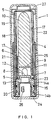
- Fig. 1 is a sectional elevation view showing one preferred embodiment of the invention and Fig. 2 is a sectional elevation view showing a cartridge taken out from a capped rotary operating cylinder.
- the reference numeral 1 designates a cartridge type cosmetic bar container according to the invention, which comprises a cartridge 2 and a capped rotary operating cylinder 3 for removably accommodating said cartridge container.
- said cartridge 2 comprises a bottomed plastic inner cylinder 5, a bottomed plastic payout cylinder 6 accommodated in said inner cylinder in vertically movable relation, a metal outer cylinder 19 in which said inner cylinder 5 is rotatably accommodated, and a metal cylindrical element 18 integrally connected to said outer cylinder.
- said inner cylinder 5 is formed with a step 16 in an intermediate part thereof, the wall of which is formed with an axially extending elongated slot 4.
- the bottom of the inner cylinder 5 is situated at a slightly elevated level with respect to the bottom edge of the peripheral wall of the inner cylinder 5 and is centrally formed with a cylindrical elevation 12.
- the payout cylinder 6 has a bottom plate 9 at a slight elevation from the bottom edge of its peripheral wall and a lipstick is held in position by this bottom plate 9 and the surrounding part of the peripheral wall.
- the lower part of the payout cylinder 6 is formed with two arch-shaped cutouts 8, with the remaining part constituting a semicircular portion 11.
- This semicircular portion 11 is resiliently inwardly deformable and, when the payout cylinder descends, enters into the gap between the outer peripheral surface of the elevation 12 and the inner circumferential surface of the inner cylinder 5.
- the outer peripheral surface of this semicircular portion 11 is formed with a projection 7 engageable with the elongated slot 4 of the inner cylinder 5.
- said payout cylinder 6 is inserted into the inner cylinder 5 in vertically movable relation and its projection 7 is engaged with the elongated slot 4 of the inner cylinder 5.
- the free end of the projection 7 extends beyond the elongated slot 4.
- the forward end of the projection 7 extends through the elongated slot 4.
- the outer cylinder 19 is slightly larger in diameter than the inner cylinder 5 and is fitted over the outer periphery of the inner cylinder 5. In this condition, the inner cylinder 5 is rotatable with respect to the outer cylinder 19.
- the reference numeral 20 indicates a ridge formed circumferentially in the lower part of the outer cylinder 19 and is rotatably engaged by the groove 14b formed in the outer peripheral surface of the inner cylinder 5 at its lower part so as to join the two cylinders 5 and 19 together.
- the reference numeral 18 indicates a cylindrical element set in position within the clearance between the step of inner cylinder 5 and the outer cylinder 19 and, as shown in Fig. 5, its peripheral wall is formed with a spiral elongated slot 17.
- the cylindrical element 18 appears as if a band-shaped material were spirally wound up to form a cylinder. It is substantially equal to the outer cylinder 19 in diameter and as positioned in said gap, it is in intimate contact with the inner circumferential surface of the outer cylinder 19 to provide an integral unit.
- the spiral elongated slot 17 of the cylindrical element 18 constitutes a spiral groove 17, the bottom of which is the inner circumferential surface of the outer cylinder 19. The free end of said projection 7 of the outer periphery of the payout cylinder 6 is engaged with said spiral groove 17 after passing through the elongated slot 4 of the inner cylinder 5.
- the capped rotary operating cylinder 3 illustrated in Fig. 2 (B) comprises a metal rotary operating cylinder 21 and a metal cap body 22.
- a flat-bottomed dish-shaped metal element 24 with a central cylindrical elevation 23 is securely pressed into the inner bottom of said metal rotary operating cylinder 21 and an intermediate metal cylinder 25 is securely fitted on top thereof.
- the top of the intermediate cylinder 25 has means for removably accepting said cap body 22.
- the outer peripheral surface of said cylindrical elevation 23 is circumferentially provided with three spring members 26 formed by making incisions into the outside wall thereof and raising the parts of incision outwards. As illustrated in Fig.
- the rotary operating cylinder 3 when the container is not used, the rotary operating cylinder 3 is manipulated to lower the payout cylinder 6 and the projection 7 is set in the horizontal slot 4b (Fig. 4) at the bottom end of the elongated slot 4 so that the payout cylinder 6 will not be paid out unintentionally.
- the cap body 22 of the capped rotary operating cylinder 3 is first released from the condition shown in Fig. 1 and the metal rotary operating cylinder 21 is rotated in one direction. This torque is transmitted to the inner cylinder 5 through the cylindrical elevation 23 at the inner bottom of the rotary operating cylinder 21 and the recess 13 of the inner cylinder 5 so that the inner cylinder 5 is rotated in one direction relative to the outer cylinder 19.
- the payout cylinder 6 ascends along the elongated slot 4 and the lipstick 10 projects out from the top openings of the inner cylinder 5 and outer cylinder 19 for ready use. Since, in this condition, the projection 7 of the payout cylinder 6 is located in the horizontal slot 4a at the top end of the elongated slot 4, even pressing the lipstick 10 hard against the lip does not cause the lipstick 10 to descend along with the payout cylinder 6.
- the recess 13 at the bottom of the inner cylinder 5 is slipped out from the cylindrical elevation 23 of the rotary operating cylinder 21, thus permitting removal of the cartridge 2.
- a fresh cartridge 2 is installed in the rotary operating cylinder 21 and the bottom recess of the inner cylinder 5 of the fresh cartridge 2 is fitted to the cylindrical elevation 23, whereupon the fresh cartridge 2 is firmly set in position.
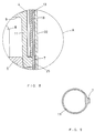
- the part of the payout cylinder 6 where the projection 7 is formed is thicker than the remaining part for added strength as illustrated in Figs. 8 and 9, it is less liable to crack and, hence, contributes to an extended useful life of the cartridge type cosmetic bar container. Furthermore, when the inner circumferential surface of the metal cylinder 18 is clad with a resin film, the burs formed at the end and spiral slot 17 of the cylinder 18 are covered up with the resin film to improve the slidability between the cylinder 18 and the plastic inner cylinder 5 contacting its inner circumferential surface in turning the rotary operating cylinder 3, whereby the foreign sensation due to abnormal friction due to the burs is eliminated.
- Such a metal cylinder 18 clad with a resin film can be obtained by coating one side of a thin metal sheet with a synthetic resin coating composition or laminating one side of a thin metal sheet with a synthetic resin sheet, then punching the coated metal sheet or metal-resin laminate and rolling the punched-out sheet.
- the above-mentioned resin film may be provided not only on the inner circumferential surface but also on the outer peripheral surface of the cylinder 18. By so doing, the intimacy of contact between the cylinder 18 and outer cylinder 19 can be further increased.
Landscapes
- Containers And Packaging Bodies Having A Special Means To Remove Contents (AREA)
Claims (3)
- Hülsenartiger Kosmetikstiftbehälter (1), der umfaßt: eine Hülse (2) umfassend einen inneren Zylinder (5), der eine Bodenwand und eine Umfangswand mit einem sich axial erstreckenden Längsschlitz (4) aufweist, einen äußeren Zylinder (19) mit einer inneren Umfangswand, die eine Schraubennut aufweist und um den äußeren Umfang des inneren Zylinders drehbar angebracht ist, und einen Ausgabezylinder (6), der einen Umfangsvorsprung (7) aufweist und drehbar in dem inneren Zylinder montiert ist, wobei der Vorsprung sich durch den Längsschlitz des inneren Zylinders erstreckt und in die Schraubennut des äußeren Zylinders eingreift, und einen Dreh-Betätigungszylinder (3), der eine Bodenwand hat und dazu geeignet ist die Hülse herausnehmbar unterzubringen, dadurch gekennzeichnet daß
der Dreh-Betätigungshylinder an seiner
inneren Bodenwand eine zylindrische Erhebung (23) und der innere Zylinder an seiner Bodenwand eine komplementäre Vertiefung für deren Eingriff aufweist, wobei die zylindrische Erhebung an ihrem äußeren Umfang eine Mehrzahl von in Umfangsrichtung in Abstand angeordneten, vorstehenden Teilen zum Druckkontakt mit der inneren Umfangsoberfläche der Vertiefung im inneren Zylinder, aufweist, und daß der innere Zylinder an seinem äußeren Umfang mit umfangslinearen (sich in Umfangsrichtung erstreckenden) elastischen Gliedern (15) zum Kontakt mit der inneren Umfangsoberfläche des äußeren Zylinders versehen ist. - Hülsenartiger Kosmetikstiftbehälter (1) nach Auspruch 1, bei dem die umfangslinearen Glieder (15) an der äußeren Umfangsoberfläche des unteren Teiles, des inneren Zylinders (5), angeordnet sind.
- Hülsenartiger Kosmetikstiftebehälter nach Anspruch 1 oder 2, bei dem ein unterer Teil des Ausgabezylinders (6) in vorbestimmten Abständen in Umfangsrichtung ausgeschnitten ist und sein zum Eingriff in die Schraubennut des äußeren Zylinders (19) vorgesehener Vorsprung (7) an dem verbleibenden Teil, des unteren Teiles, des Ausgabezylinders angeordnet ist.
Priority Applications (1)
| Application Number | Priority Date | Filing Date | Title |
|---|---|---|---|
| DE1989616431 DE68916431T2 (de) | 1989-11-16 | 1989-11-16 | Ersatzstiftbehälter für kosmetische Stifte. |
Applications Claiming Priority (1)
| Application Number | Priority Date | Filing Date | Title |
|---|---|---|---|
| US07/434,753 US4961663A (en) | 1989-11-13 | 1989-11-13 | Cartridge type cosmetic bar container |
Publications (2)
| Publication Number | Publication Date |
|---|---|
| EP0428794A1 EP0428794A1 (de) | 1991-05-29 |
| EP0428794B1 true EP0428794B1 (de) | 1994-06-22 |
Family
ID=23725533
Family Applications (1)
| Application Number | Title | Priority Date | Filing Date |
|---|---|---|---|
| EP89311891A Expired - Lifetime EP0428794B1 (de) | 1989-11-13 | 1989-11-16 | Ersatzstiftbehälter für kosmetische Stifte |
Country Status (3)
| Country | Link |
|---|---|
| US (1) | US4961663A (de) |
| EP (1) | EP0428794B1 (de) |
| ES (1) | ES2055102T3 (de) |
Families Citing this family (24)
| Publication number | Priority date | Publication date | Assignee | Title |
|---|---|---|---|---|
| EP0554497A1 (de) * | 1992-02-07 | 1993-08-11 | Wilco Consultants Limited | Kosmetikstifthalter |
| EP0554496B1 (de) * | 1992-02-12 | 1996-05-08 | Wilco Consultants Limited | Kosmetikstifthalter |
| DE4206299C2 (de) * | 1992-02-28 | 1996-01-25 | Hevco Ag | Stiftträger mit auswechselbarer Stifteinheit |
| US5399040A (en) * | 1993-07-06 | 1995-03-21 | Risdon Corporation | Dispenser with replaceable cosmetic holder |
| KR100238356B1 (ko) * | 1993-09-08 | 2000-01-15 | 호소에이사오 | 고상물공급용 카트리지형 공급케이스 |
| FR2713455B1 (fr) * | 1993-12-14 | 1996-02-02 | Oreal | Dispositif pour appliquer un produit pâteux, en particulier un produit cosmétique tel que du rouge à lèvres. |
| FR2715037B1 (fr) * | 1994-01-20 | 1996-03-01 | Cosmoplast Sa | Mécanisme d'étui tournant de rouge à lèvres. |
| JP2736039B2 (ja) * | 1994-08-25 | 1998-04-02 | 株式会社トキワ | 化粧料繰り出し容器 |
| US5649777A (en) * | 1994-11-08 | 1997-07-22 | Risdon Corporation | Cosmetic dispenser with locking cup replaceable cartridge |
| ES2096526B1 (es) * | 1995-02-04 | 1997-11-01 | Castello Ind Met | Envase para lapiz de labios con mecanismo de barra recargable. |
| US5533823A (en) * | 1995-03-29 | 1996-07-09 | Rexam Cosmetic Packaging Inc. | Sealed cosmetic dispenser |
| GB2307226B (en) * | 1995-11-16 | 1999-03-03 | Cheng Yuan Su | Lipstick tube with a replaceable lipstick seat |
| US5851079A (en) * | 1996-10-25 | 1998-12-22 | The Procter & Gamble Company | Simplified undirectional twist-up dispensing device with incremental dosing |
| FR2762763B1 (fr) * | 1997-05-05 | 1999-07-09 | Oreal | Dispositif de conditionnement et d'application d'un produit delitable |
| JP3675176B2 (ja) * | 1998-06-19 | 2005-07-27 | 株式会社カツシカ | 棒状化粧料繰り出し容器 |
| US6035866A (en) * | 1998-09-03 | 2000-03-14 | Eyelematic Manufacturing Co., Inc. | Pomade stick applicator with resilient sealing features |
| USD416356S (en) | 1998-09-28 | 1999-11-09 | The Procter & Gamble Company | Container |
| JP3921366B2 (ja) * | 2001-09-18 | 2007-05-30 | 株式会社ヒダン | 棒状物品の繰り出し容器 |
| CN102740728B (zh) | 2010-01-12 | 2015-03-04 | 欧莱雅公司 | 用于展开化妆品棒的机构、相关的设备和方法 |
| US9179755B2 (en) * | 2013-05-07 | 2015-11-10 | MoreStick, LLC | Assembly for dispensing a cosmetic stick |
| CN106108548B (zh) * | 2016-08-23 | 2017-09-22 | 泉州市嘉鑫信息服务有限公司 | 茶杯 |
| FR3048346B1 (fr) * | 2016-09-21 | 2018-04-20 | Reboul S.A.S. | Moyens de blocage d’etui cosmetique |
| FR3084248B1 (fr) * | 2018-07-30 | 2021-06-18 | Metapack | Systeme de support pour un crayon cosmetique |
| US11639256B2 (en) * | 2020-08-25 | 2023-05-02 | Raymond G. Anderson | Non-roll stick product containers |
Family Cites Families (10)
| Publication number | Priority date | Publication date | Assignee | Title |
|---|---|---|---|---|
| US2529673A (en) * | 1946-11-16 | 1950-11-14 | Blake Lucille | Lipstick holder |
| FR1052053A (fr) * | 1952-03-04 | 1954-01-21 | Coty Sa | Dispositif de rechange pour rouge à lèvres et matières analogues en étui |
| BE518825A (de) * | 1953-01-30 | |||
| US3146881A (en) * | 1962-05-21 | 1964-09-01 | Int Silver Co | Cartridge type refillable lipstick container |
| DE1891095U (de) * | 1963-12-05 | 1964-04-16 | Niedersaechsische Kunststoff G | Lippenstifthuelse mit kunststoff-drehmechanik. |
| US3335854A (en) * | 1965-05-19 | 1967-08-15 | Int Silver Co | Cartridge-type lipstick container or the like |
| US3991775A (en) * | 1975-02-24 | 1976-11-16 | Spatz Corporation | Cosmetic applicator |
| JPS5825941Y2 (ja) * | 1981-03-25 | 1983-06-04 | 吉田工業株式会社 | 繰出し式化粧料容器 |
| FR2571231B3 (fr) * | 1984-10-10 | 1986-11-21 | Reboul Smt | Etui tubulaire stabilise en position verticale |
| FR2588167B1 (fr) * | 1985-10-03 | 1988-01-08 | Oreal | Dispositif pour appliquer un produit pateux, notamment un produit cosmetique tel que du rouge a levres, presente sous forme de baton |
-
1989
- 1989-11-13 US US07/434,753 patent/US4961663A/en not_active Expired - Fee Related
- 1989-11-16 ES ES89311891T patent/ES2055102T3/es not_active Expired - Lifetime
- 1989-11-16 EP EP89311891A patent/EP0428794B1/de not_active Expired - Lifetime
Also Published As
| Publication number | Publication date |
|---|---|
| EP0428794A1 (de) | 1991-05-29 |
| ES2055102T3 (es) | 1994-08-16 |
| US4961663A (en) | 1990-10-09 |
Similar Documents
| Publication | Publication Date | Title |
|---|---|---|
| US4961663A (en) | Cartridge type cosmetic bar container | |
| CA2085080C (en) | Device for identifying an ink ribbon cartridge used in a printer | |
| US5492282A (en) | Refillable tape cassettes of varying thicknesses with unique spool mounting structures | |
| US6500259B1 (en) | Coat film transfer tape cartridge and coat film transfer tool | |
| EP0770572B1 (de) | Mechanismus zum Zuführen und Aufwickeln eines Übertragungsbands in einer Auftragvorrichtung | |
| US6830089B1 (en) | Coat film transfer head device and coat film transfer tool | |
| EP0638434A2 (de) | Farbbandkassette | |
| WO1992012909A1 (en) | Indicator cap | |
| EP0288932A1 (de) | Einheitliche Kassette mit Aufzeichnungs- und Farbband für ein Drucksystem | |
| CN1651104A (zh) | 用于喷雾剂容器的显示装置 | |
| CN102905979A (zh) | 药片盒 | |
| CA1192831A (en) | Roller shade return mechanism | |
| US11812840B2 (en) | Container for a cosmetic product and refill for such a container | |
| EP0767128B1 (de) | Kupplungsmechanismus eines Übertragungswerkzeuges für Beschichtungsfilme und Übertragungswerkzeug für Beschichtungsfilme | |
| KR960041693A (ko) | 리코일 시동기 | |
| US20130248315A1 (en) | Rotating part for image forming apparatus, cartridge for forming image, and image forming apparatus | |
| US6623193B1 (en) | One piece clutch mechanism with drive gear | |
| EP1101421B1 (de) | Kosmetikbehälter mit zugehöriger patrone | |
| JP3870986B2 (ja) | 塗布具の供給リール | |
| JPH0723268Y2 (ja) | 転写フイルムカセットの回転止め機構 | |
| US6905268B1 (en) | Clutch mechanism with one piece plastic spool | |
| US6095448A (en) | Microfilm cartridge assembly | |
| JP4454327B2 (ja) | 二液吐出容器 | |
| KR200174210Y1 (ko) | 드래그 력 조정시에 클릭 음을 발생시킬 수 있는 낚시용 릴 | |
| JPH08275823A (ja) | 棒状化粧料容器 |
Legal Events
| Date | Code | Title | Description |
|---|---|---|---|
| PUAI | Public reference made under article 153(3) epc to a published international application that has entered the european phase |
Free format text: ORIGINAL CODE: 0009012 |
|
| 17P | Request for examination filed |
Effective date: 19910109 |
|
| AK | Designated contracting states |
Kind code of ref document: A1 Designated state(s): CH DE ES FR GB IT LI NL |
|
| 17Q | First examination report despatched |
Effective date: 19930201 |
|
| GRAA | (expected) grant |
Free format text: ORIGINAL CODE: 0009210 |
|
| AK | Designated contracting states |
Kind code of ref document: B1 Designated state(s): CH DE ES FR GB IT LI NL |
|
| REF | Corresponds to: |
Ref document number: 68916431 Country of ref document: DE Date of ref document: 19940728 |
|
| REG | Reference to a national code |
Ref country code: ES Ref legal event code: FG2A Ref document number: 2055102 Country of ref document: ES Kind code of ref document: T3 |
|
| ITF | It: translation for a ep patent filed | ||
| ET | Fr: translation filed | ||
| PLBE | No opposition filed within time limit |
Free format text: ORIGINAL CODE: 0009261 |
|
| STAA | Information on the status of an ep patent application or granted ep patent |
Free format text: STATUS: NO OPPOSITION FILED WITHIN TIME LIMIT |
|
| 26N | No opposition filed | ||
| PGFP | Annual fee paid to national office [announced via postgrant information from national office to epo] |
Ref country code: FR Payment date: 19951013 Year of fee payment: 7 |
|
| PGFP | Annual fee paid to national office [announced via postgrant information from national office to epo] |
Ref country code: ES Payment date: 19951024 Year of fee payment: 7 Ref country code: DE Payment date: 19951024 Year of fee payment: 7 |
|
| PGFP | Annual fee paid to national office [announced via postgrant information from national office to epo] |
Ref country code: GB Payment date: 19951108 Year of fee payment: 7 |
|
| PGFP | Annual fee paid to national office [announced via postgrant information from national office to epo] |
Ref country code: CH Payment date: 19951117 Year of fee payment: 7 |
|
| PGFP | Annual fee paid to national office [announced via postgrant information from national office to epo] |
Ref country code: NL Payment date: 19951130 Year of fee payment: 7 |
|
| PG25 | Lapsed in a contracting state [announced via postgrant information from national office to epo] |
Ref country code: GB Effective date: 19961116 |
|
| PG25 | Lapsed in a contracting state [announced via postgrant information from national office to epo] |
Ref country code: ES Free format text: LAPSE BECAUSE OF EXPIRATION OF PROTECTION Effective date: 19961118 |
|
| PG25 | Lapsed in a contracting state [announced via postgrant information from national office to epo] |
Ref country code: LI Effective date: 19961130 Ref country code: CH Effective date: 19961130 |
|
| PG25 | Lapsed in a contracting state [announced via postgrant information from national office to epo] |
Ref country code: NL Effective date: 19970601 |
|
| GBPC | Gb: european patent ceased through non-payment of renewal fee |
Effective date: 19961116 |
|
| REG | Reference to a national code |
Ref country code: CH Ref legal event code: PL |
|
| PG25 | Lapsed in a contracting state [announced via postgrant information from national office to epo] |
Ref country code: FR Effective date: 19970731 |
|
| NLV4 | Nl: lapsed or anulled due to non-payment of the annual fee |
Effective date: 19970601 |
|
| PG25 | Lapsed in a contracting state [announced via postgrant information from national office to epo] |
Ref country code: DE Effective date: 19970801 |
|
| REG | Reference to a national code |
Ref country code: FR Ref legal event code: ST |
|
| REG | Reference to a national code |
Ref country code: ES Ref legal event code: FD2A Effective date: 20010301 |
|
| PG25 | Lapsed in a contracting state [announced via postgrant information from national office to epo] |
Ref country code: IT Free format text: LAPSE BECAUSE OF NON-PAYMENT OF DUE FEES Effective date: 20051116 |