EP0428840A2 - Radaufhängung - Google Patents
Radaufhängung Download PDFInfo
- Publication number
- EP0428840A2 EP0428840A2 EP90116955A EP90116955A EP0428840A2 EP 0428840 A2 EP0428840 A2 EP 0428840A2 EP 90116955 A EP90116955 A EP 90116955A EP 90116955 A EP90116955 A EP 90116955A EP 0428840 A2 EP0428840 A2 EP 0428840A2
- Authority
- EP
- European Patent Office
- Prior art keywords
- wheel
- joint
- guide member
- joints
- bearing element
- Prior art date
- Legal status (The legal status is an assumption and is not a legal conclusion. Google has not performed a legal analysis and makes no representation as to the accuracy of the status listed.)
- Granted
Links
Images

Classifications
-
- B—PERFORMING OPERATIONS; TRANSPORTING
- B60—VEHICLES IN GENERAL
- B60G—VEHICLE SUSPENSION ARRANGEMENTS
- B60G15/00—Resilient suspensions characterised by arrangement, location or type of combined spring and vibration damper, e.g. telescopic type
- B60G15/08—Resilient suspensions characterised by arrangement, location or type of combined spring and vibration damper, e.g. telescopic type having fluid spring
- B60G15/12—Resilient suspensions characterised by arrangement, location or type of combined spring and vibration damper, e.g. telescopic type having fluid spring and fluid damper
-
- B—PERFORMING OPERATIONS; TRANSPORTING
- B60—VEHICLES IN GENERAL
- B60G—VEHICLE SUSPENSION ARRANGEMENTS
- B60G13/00—Resilient suspensions characterised by arrangement, location or type of vibration dampers
- B60G13/001—Arrangements for attachment of dampers
-
- B—PERFORMING OPERATIONS; TRANSPORTING
- B60—VEHICLES IN GENERAL
- B60G—VEHICLE SUSPENSION ARRANGEMENTS
- B60G3/00—Resilient suspensions for a single wheel
- B60G3/18—Resilient suspensions for a single wheel with two or more pivoted arms, e.g. parallelogram
- B60G3/20—Resilient suspensions for a single wheel with two or more pivoted arms, e.g. parallelogram all arms being rigid
-
- B—PERFORMING OPERATIONS; TRANSPORTING
- B60—VEHICLES IN GENERAL
- B60G—VEHICLE SUSPENSION ARRANGEMENTS
- B60G7/00—Pivoted suspension arms; Accessories thereof
- B60G7/005—Ball joints
-
- B—PERFORMING OPERATIONS; TRANSPORTING
- B60—VEHICLES IN GENERAL
- B60G—VEHICLE SUSPENSION ARRANGEMENTS
- B60G2202/00—Indexing codes relating to the type of spring, damper or actuator
- B60G2202/30—Spring/Damper and/or actuator Units
- B60G2202/31—Spring/Damper and/or actuator Units with the spring arranged around the damper, e.g. MacPherson strut
- B60G2202/314—The spring being a pneumatic spring
-
- B—PERFORMING OPERATIONS; TRANSPORTING
- B60—VEHICLES IN GENERAL
- B60G—VEHICLE SUSPENSION ARRANGEMENTS
- B60G2204/00—Indexing codes related to suspensions per se or to auxiliary parts
- B60G2204/10—Mounting of suspension elements
- B60G2204/12—Mounting of springs or dampers
- B60G2204/128—Damper mount on vehicle body or chassis
-
- B—PERFORMING OPERATIONS; TRANSPORTING
- B60—VEHICLES IN GENERAL
- B60G—VEHICLE SUSPENSION ARRANGEMENTS
- B60G2204/00—Indexing codes related to suspensions per se or to auxiliary parts
- B60G2204/40—Auxiliary suspension parts; Adjustment of suspensions
- B60G2204/41—Elastic mounts, e.g. bushings
-
- B—PERFORMING OPERATIONS; TRANSPORTING
- B60—VEHICLES IN GENERAL
- B60G—VEHICLE SUSPENSION ARRANGEMENTS
- B60G2204/00—Indexing codes related to suspensions per se or to auxiliary parts
- B60G2204/40—Auxiliary suspension parts; Adjustment of suspensions
- B60G2204/416—Ball or spherical joints
-
- Y—GENERAL TAGGING OF NEW TECHNOLOGICAL DEVELOPMENTS; GENERAL TAGGING OF CROSS-SECTIONAL TECHNOLOGIES SPANNING OVER SEVERAL SECTIONS OF THE IPC; TECHNICAL SUBJECTS COVERED BY FORMER USPC CROSS-REFERENCE ART COLLECTIONS [XRACs] AND DIGESTS
- Y10—TECHNICAL SUBJECTS COVERED BY FORMER USPC
- Y10T—TECHNICAL SUBJECTS COVERED BY FORMER US CLASSIFICATION
- Y10T403/00—Joints and connections
- Y10T403/32—Articulated members
- Y10T403/32008—Plural distinct articulation axes
- Y10T403/32032—Plural ball and socket
-
- Y—GENERAL TAGGING OF NEW TECHNOLOGICAL DEVELOPMENTS; GENERAL TAGGING OF CROSS-SECTIONAL TECHNOLOGIES SPANNING OVER SEVERAL SECTIONS OF THE IPC; TECHNICAL SUBJECTS COVERED BY FORMER USPC CROSS-REFERENCE ART COLLECTIONS [XRACs] AND DIGESTS
- Y10—TECHNICAL SUBJECTS COVERED BY FORMER USPC
- Y10T—TECHNICAL SUBJECTS COVERED BY FORMER US CLASSIFICATION
- Y10T403/00—Joints and connections
- Y10T403/32—Articulated members
- Y10T403/32606—Pivoted
- Y10T403/32631—Universal ball and socket
- Y10T403/32681—Composite ball
- Y10T403/32704—Stud extends into ball
Definitions
- the invention relates to a wheel suspension according to the preamble of claim 1.
- the object of the invention is to provide a wheel suspension which has a small interference lever arm with an optimal damper ratio, in which the forces from the shock absorber and the lower wheel control arm are divided.
- the main advantages achieved with the invention are that a large support base and thus an optimal damper ratio is achieved by the position of the handlebar articulation points in the rim of the vehicle wheel.
- the position of the joints near the vertical longitudinal plane of the wheel center result in a low interference arm, which is contributed by the joints arranged jointly in the bearing element of the wheel carrier for the lower link and the shock absorber.
- These joints are arranged one above the other in the wheel carrier and lie in a wheel pivot axis extending through the joint of the upper wheel guide member.
- the joint of the lower link is designed as a hanging joint and is provided separately from the standing joint of the shock absorber.
- the hanging joint for the lower handlebar is free of spring forces and thus more definable and safer.
- the lower handlebar can be made lighter because it is free of spring forces and only acts as a tension and compression strut.
- the wheel suspension 1 comprises an upper link 4 connected to the wheel carrier 2 via a joint 3 - with respect to the wheel axis of rotation R - and a lower link 6 held in a bearing element 5, in which a spring strut 7 is supported with its lower end.
- the bearing element 5 comprises a first standing bearing 8 for the shock absorber 7 and a second hanging bearing 9 for the lower link 6.
- bearings 8 and 9 consist of ball joints and are supported in a ring 10 of the wheel carrier 2.
- the ball joints 8 and 9 have necks 11 and 12, which are tapered and are fitted into corresponding receptacles of the ring 10.
- the ball joints are fastened in the ring 10 by means of a bolt 13, which can be screwed into the standing ball joint 8 with a thread 14 and is supported with its head in the ball joint 9.
- the ball joints 8 and 9 of the bearing element 5 are arranged such that the pivot axis 14 of the wheel 15 through the center axis M of the joint 3 of the upper link 4 and through the center axis of the joints 8 and 9 of the bearing element 5 and the strut runs.
- the pivot axis 14 can only form a small interference lever arm with the distance a due to the joints 3, 8 and 9 which are moved close to the vertical longitudinal plane XX of the wheel center.
- the position of the joints 3, 8 and 9 in the bowl 17 of the rim 16 provides a relatively large support base with the distance b, which results in an optimal damper ratio b / c which is ⁇ 0.9.
- the joint 9 for the lower link 6 is separated in terms of strength from the joint 8 for the spring strut, so that the lower joint is kept free of supporting forces of the spring strut 7 and can therefore be dimensioned more easily and security against failure is ensured.
Landscapes
- Engineering & Computer Science (AREA)
- Mechanical Engineering (AREA)
- Vehicle Body Suspensions (AREA)
- Pivots And Pivotal Connections (AREA)
- Steering-Linkage Mechanisms And Four-Wheel Steering (AREA)
Abstract
Description
- Die Erfindung bezieht sich auf eine Radaufhängung nach dem Oberbegriff des Anspruchs 1.
- Es ist aus der GB-PS 2 176 158 eine Radaufhängung mit einem - in bezug auf die Raddrehachse - oberen und unteren Lenker bekannt, die am Radträger in Lagern angelenkt sind. Eine weitere Lagerung ist für den unteren Abstützpunkt des federbeines am Radträger vorgesehen, der nach innen zur Fahrzeuglängsmittenachse hin verlagert ist. Eine Radschwenkung erfolgt über ein durch die Gelenke der beiden Radlenker verlaufende Schwenkachse, wobei der untere Abstützpunkt für das Federbein im Abstand zum unteren Lenkerpunkt angeordnet ist, was zu einer nachteiligen Momentenbildung bei einer Verschwenkung des Rades beiträgt.
- Aufgabe der Erfindung ist es, eine Radaufhängung zu schaffen, die einen kleinen Störkrafthebelarm bei einer optimalen Dämpferübersetzung aufweist, bei der eine Aufteilung der Kräfte vom Federbein und vom unteren Radführungslenker erfolgt.
- Diese Aufgabe wird erfindungsgemäß durch die kennzeichnenden Merkmale des Anspruchs 1 gelöst. Weitere vorteilhafte Merkmale beinhalten die Unteransprüche.
- Die mit der Erfindung hauptsächlich erzielten Vorteile bestehen darin, daß durch die Lage der lenkerseitigen Gelenkpunkte in der Felge des Fahrzeugrades eine große Stützbasis und somit ein optimales Dämpferverhältnis erzielt wird. Die Lage der Gelenke nahe der senkrechten Radmittenlängsebene ergeben einen geringen Störkrafthebelarm, wozu die gemeinsam im Lagerelement des Radträgers angeordneten Gelenke für den unteren Lenker und das Federbein beitragen.
- Diese Gelenke sind übereinander angeordnet im Radträger gehalten und liegen in einer durch das Gelenk des oberen Radführungsgliedes verlaufenden Radschwenkachse.
- Das Gelenk des unteren Lenkers ist als hängendes Gelenk ausgeführt und getrennt vom stehenden Gelenk des Federbeines vorgesehen. Hierdurch ist das hängende Gelenk für den unteren Lenker frei von Federkräften und damit definierter auslegbar und sicherer. Außerdem kann der untere Lenker leichter gebaut werden, da er frei von Federkräften ist und nur als Zug- und Druckstrebe wirkt.
- Ein Ausführungsbeispiel der Erfindung ist in der Zeichnung dargestellt und wird im folgenden näher beschrieben.
- Es zeigen
- Fig. 1 eine Vorderansicht einer Radaufhängung mit zwei Querlenkern und einem Federbein und
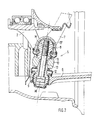
- Fig. 2 eine vergrößerte Darstellung eines Lagerelements zur gelenkigen Abstützung eines - in bezug auf die Raddrehachse - unteren Lenkers und eines Federbeines.
- Die Radaufhängung 1 umfaßt einen mit dem Radträger 2 über ein Gelenk 3 verbundenen - in bezug auf die Raddrehachse R - oberen Querlenker 4 sowie einen in einem Lagerelement 5 gehaltenen unteren Lenker 6, in dem gleichzeitig ein Federbein 7 mit seinem unteren Ende abgestützt ist.
- Das Lagerelement 5 umfaßt ein erstes stehendes Lager 8 für das Federbein 7 und ein zweites hängendes Lager 9 für den unteren Lenker 6.
- Diese Lager 8 und 9 bestehen aus Kugelgelenken und stützen sich in einem Ring 10 des Radträgers 2 ab. Hierzu weisen die Kugelgelenke 8 und 9 Hälse 11 und 12 auf, welche konisch zulaufend ausgeführt sind und in entsprechende Aufnahmen des Ringes 10 eingepaßt werden. Eine Befestigung der Kugelgelenke im Ring 10 erfolgt über einen Bolzen 13, der mit einem Gewinde 14 in das stehende Kugelgelenk 8 einschraubbar ist und sich im Kugelgelenk 9 mit seinem Kopf abstützt.
- Die Kugelgelenke 8 und 9 des Lagerelements 5 sind so angeordnet, daß die Schwenkachse 14 des Rades 15 durch die Mittenachse M des Gelenks 3 des oberen Lenkers 4 und durch die Mittenachse der Gelenke 8 und 9 des Lagerelements 5 sowie des Federbeines verläuft. Die Schwenkachse 14 kann durch die nah an die senkrechte Radmittenlängsebene X-X herangerückten Gelenke 3, 8 und 9 nur einen kleinen Störkrafthebelarm mit dem Abstand a bilden. Desweiteren wird durch die Lage der Gelenke 3, 8 und 9 in der Schüssel 17 der Felge 16 eine relativ große Stützbasis mit dem Abstand b erzielt, wodurch sich eine optimale Dämpferübersetzung b/c ergibt, welche < 0,9 beträgt.
- Das Gelenk 9 für den unteren Lenker 6 ist kräftemäßig getrennt vom Gelenk 8 für das Federbein, so daß das untere Gelenk frei von Stützkräften des Federbeines 7 gehalten ist und somit leichter dimensioniert werden kann und eine Sicherheit gegen Ausfall gewährleistet ist.
Claims (6)
Applications Claiming Priority (2)
| Application Number | Priority Date | Filing Date | Title |
|---|---|---|---|
| DE3938475 | 1989-11-20 | ||
| DE3938475A DE3938475A1 (de) | 1989-11-20 | 1989-11-20 | Radaufhaengung |
Publications (3)
| Publication Number | Publication Date |
|---|---|
| EP0428840A2 true EP0428840A2 (de) | 1991-05-29 |
| EP0428840A3 EP0428840A3 (en) | 1991-12-04 |
| EP0428840B1 EP0428840B1 (de) | 1993-11-03 |
Family
ID=6393855
Family Applications (1)
| Application Number | Title | Priority Date | Filing Date |
|---|---|---|---|
| EP90116955A Expired - Lifetime EP0428840B1 (de) | 1989-11-20 | 1990-09-04 | Radaufhängung |
Country Status (5)
| Country | Link |
|---|---|
| US (1) | US5062655A (de) |
| EP (1) | EP0428840B1 (de) |
| JP (1) | JPH03176214A (de) |
| DE (2) | DE3938475A1 (de) |
| ES (1) | ES2045697T3 (de) |
Cited By (1)
| Publication number | Priority date | Publication date | Assignee | Title |
|---|---|---|---|---|
| DE4212696A1 (de) * | 1992-04-16 | 1993-10-21 | Teves Gmbh Alfred | Radaufhängung für Kraftfahrzeuge |
Families Citing this family (20)
| Publication number | Priority date | Publication date | Assignee | Title |
|---|---|---|---|---|
| DE4238577A1 (de) * | 1992-11-16 | 1994-05-19 | Kloeckner Humboldt Deutz Ag | Dichtheitsprüfverfahren und Dichtheitsprüfvorrichtung |
| DE9306932U1 (de) * | 1993-05-07 | 1993-07-08 | Dr.Ing.H.C. F. Porsche Ag, 7000 Stuttgart | Befestigungsvorrichtung |
| CA2140174C (en) * | 1994-02-07 | 2000-08-22 | Eric G. Parker | Pivotal ball-end link |
| US5473955A (en) * | 1994-04-04 | 1995-12-12 | Ford Motor Company | Wiper system double ball joint |
| US6338589B1 (en) * | 1998-07-14 | 2002-01-15 | American Axle & Manufacturing, Inc. | Hybrid ball stud |
| DE10038267B4 (de) * | 2000-08-04 | 2009-01-02 | Audi Ag | Vorrichtung zur karosserieseitigen Lagerung eines Federbeines |
| JP4031917B2 (ja) * | 2001-06-20 | 2008-01-09 | 本田技研工業株式会社 | サスペンション構造 |
| US6752410B2 (en) * | 2001-12-28 | 2004-06-22 | Meritor Heavy Vehicle Technology, Llc | Independent suspension for low profile vehicles |
| US20030133744A1 (en) * | 2002-01-15 | 2003-07-17 | Trw Inc. | Ball joint with dual tapered connection |
| US6719312B2 (en) * | 2002-01-22 | 2004-04-13 | Trw Inc. | Steering linkage and ball joint |
| DE10257592A1 (de) * | 2002-12-09 | 2004-07-15 | Valeo Wischersysteme Gmbh | Kugelbolzen und Kugelgelenk mit einem solchen Kugelbolzen |
| DE20313665U1 (de) * | 2003-09-03 | 2004-01-29 | Trw Fahrwerksysteme Gmbh & Co Kg | System zur Wankwinkelverringerung bei Kraftfahrzeugen |
| EP1764042A3 (de) * | 2005-09-12 | 2009-08-26 | Arthrex, Inc. | Druckklammer |
| US7320555B2 (en) * | 2005-10-14 | 2008-01-22 | Sercomm Corporation | Cardan shaft structure with tightness adjustable functions |
| US8240687B2 (en) * | 2007-07-04 | 2012-08-14 | Honda Motor Co., Ltd. | Wheel suspension system for a steerable wheel |
| US8136824B2 (en) * | 2008-08-20 | 2012-03-20 | Agco Corporation | Suspension assemblies with bump steer control |
| DE102012223609A1 (de) * | 2012-12-18 | 2014-06-18 | Zf Friedrichshafen Ag | Gelenkeinrichtung für ein Kraftfahrzeug |
| US11098752B2 (en) * | 2019-06-24 | 2021-08-24 | Federal-Mogul Motorparts Llc | Ball joint with a multi-piece ball stud |
| DE102022200672B4 (de) * | 2022-01-21 | 2025-07-24 | Volkswagen Aktiengesellschaft | Radaufhängung eines Kraftfahrzeugs sowie Kraftfahrzeug mit einer solchen |
| DE102023107011A1 (de) * | 2023-03-21 | 2024-09-26 | Audi Aktiengesellschaft | Radaufhängung für ein Rad einer Achse eines Kraftfahrzeugs sowie Kraftfahrzeug |
Family Cites Families (7)
| Publication number | Priority date | Publication date | Assignee | Title |
|---|---|---|---|---|
| US2123087A (en) * | 1935-07-18 | 1938-07-05 | John W Leighton | Individual wheel suspension |
| GB870789A (en) * | 1959-01-13 | 1961-06-21 | Ustav Pro Vyzkum Motorovych Vo | A motor vehicle front axle assembly |
| DE1405372A1 (de) * | 1959-04-08 | 1968-10-03 | Opel Adam Ag | Radaufhaengung an Kraftfahrzeugen |
| US3061329A (en) * | 1960-06-30 | 1962-10-30 | Ford Motor Co | Vehicle suspension |
| GB921908A (en) * | 1960-12-10 | 1963-03-27 | Tom Edgerton Clarke Hirst | Mechanical linkage joint |
| JPS61278408A (ja) * | 1985-06-03 | 1986-12-09 | Honda Motor Co Ltd | 独立懸架式リヤサスペンシヨン |
| US4810002A (en) * | 1986-07-15 | 1989-03-07 | Nissan Motor Co., Ltd. | Double link type suspension system |
-
1989
- 1989-11-20 DE DE3938475A patent/DE3938475A1/de not_active Withdrawn
-
1990
- 1990-09-04 DE DE90116955T patent/DE59003341D1/de not_active Expired - Fee Related
- 1990-09-04 EP EP90116955A patent/EP0428840B1/de not_active Expired - Lifetime
- 1990-09-04 ES ES90116955T patent/ES2045697T3/es not_active Expired - Lifetime
- 1990-11-06 US US07/609,635 patent/US5062655A/en not_active Expired - Fee Related
- 1990-11-20 JP JP2313023A patent/JPH03176214A/ja active Pending
Cited By (1)
| Publication number | Priority date | Publication date | Assignee | Title |
|---|---|---|---|---|
| DE4212696A1 (de) * | 1992-04-16 | 1993-10-21 | Teves Gmbh Alfred | Radaufhängung für Kraftfahrzeuge |
Also Published As
| Publication number | Publication date |
|---|---|
| EP0428840B1 (de) | 1993-11-03 |
| DE3938475A1 (de) | 1991-05-23 |
| US5062655A (en) | 1991-11-05 |
| JPH03176214A (ja) | 1991-07-31 |
| EP0428840A3 (en) | 1991-12-04 |
| ES2045697T3 (es) | 1994-01-16 |
| DE59003341D1 (de) | 1993-12-09 |
Similar Documents
| Publication | Publication Date | Title |
|---|---|---|
| EP0428840A2 (de) | Radaufhängung | |
| EP0290587B1 (de) | Einzelradaufhängung für ein Kraftfahrzeug, insbesondere einen Omnibus | |
| DE60008460T2 (de) | Mit einem System zur Steuerung des Radsturzwinkels des Fahrzeugs in Kurven ausgestattetes Kraftfahrzeug | |
| EP0312711B1 (de) | Radaufhängung für ein Kraftfahrzeug | |
| DE19521875C2 (de) | Achsaufhängung für Starrachsen in Fahrzeugen | |
| DE19903562B4 (de) | Radaufhängung für ein Fahrzeug | |
| EP0291794B1 (de) | Unabhängige Radaufhängung für lenkbare Räder von Kraftfahrzeugen | |
| EP1076783B1 (de) | Lagerung für ein dämpferbein oder eine luftfeder einer radaufhängung | |
| DE2747561A1 (de) | Einzelradaufhaengung fuer kraftfahrzeuge | |
| EP0389685A1 (de) | Radaufhängung für die Vorderräder eines Kraftfahrzeuges | |
| EP0494394B1 (de) | Unabhängige Radaufhängung für Kraftfahrzeuge | |
| DE1430850B1 (de) | Lagerung eines zur Fuehrung eines Kraftfahrzeugrades dienenden Querlenkers | |
| DE3782569T2 (de) | Radaufhaengung. | |
| EP0365516B1 (de) | Radführung für lenkbare und antriebsfähige Räder von Kraftfahrzeugen | |
| DE4342809A1 (de) | Verfahren und Anordnung zur Befestigung eines federnd auf einem Fahrzeugrahmen gelagerten Fahrerhauses | |
| DE2820585A1 (de) | Unabhaengige aufhaengung der gelenkten vorderraeder von kraftfahrzeugen | |
| DE202017100164U1 (de) | Hinterradaufhängung für Kraftfahrzeuge | |
| DE1864224U (de) | Oelpneumatische aufhaengung fuer kraftfahrzeuge. | |
| DE19615207C1 (de) | Hilfsrahmen | |
| DE69713696T2 (de) | Aufhängungsvorrichtung, insbesondere für Kraftfahrzeuge | |
| DE2507071B2 (de) | Obere lagerung eines einen radachsschenkel tragenden teleskopstossdaempfers fuer kraftfahrzeuge | |
| DE69325134T2 (de) | Hinterradaufhängung für Kraftfahrzeug mit unabhängigen Rädern | |
| DE4426881C2 (de) | Lenkbare Radaufhängung | |
| DE19960457A1 (de) | Lagerung für ein Dämpferbein oder eine Luftfeder einer Radaufhängung | |
| DE4125300C2 (de) | Lenkeinrichtung |
Legal Events
| Date | Code | Title | Description |
|---|---|---|---|
| PUAI | Public reference made under article 153(3) epc to a published international application that has entered the european phase |
Free format text: ORIGINAL CODE: 0009012 |
|
| AK | Designated contracting states |
Kind code of ref document: A2 Designated state(s): DE ES FR GB IT |
|
| PUAL | Search report despatched |
Free format text: ORIGINAL CODE: 0009013 |
|
| AK | Designated contracting states |
Kind code of ref document: A3 Designated state(s): DE ES FR GB IT |
|
| 17P | Request for examination filed |
Effective date: 19920414 |
|
| 17Q | First examination report despatched |
Effective date: 19930322 |
|
| ITF | It: translation for a ep patent filed | ||
| GRAA | (expected) grant |
Free format text: ORIGINAL CODE: 0009210 |
|
| AK | Designated contracting states |
Kind code of ref document: B1 Designated state(s): DE ES FR GB IT |
|
| REF | Corresponds to: |
Ref document number: 59003341 Country of ref document: DE Date of ref document: 19931209 |
|
| ET | Fr: translation filed | ||
| GBT | Gb: translation of ep patent filed (gb section 77(6)(a)/1977) |
Effective date: 19931208 |
|
| REG | Reference to a national code |
Ref country code: ES Ref legal event code: FG2A Ref document number: 2045697 Country of ref document: ES Kind code of ref document: T3 |
|
| PLBE | No opposition filed within time limit |
Free format text: ORIGINAL CODE: 0009261 |
|
| STAA | Information on the status of an ep patent application or granted ep patent |
Free format text: STATUS: NO OPPOSITION FILED WITHIN TIME LIMIT |
|
| PG25 | Lapsed in a contracting state [announced via postgrant information from national office to epo] |
Ref country code: ES Free format text: LAPSE BECAUSE OF EXPIRATION OF PROTECTION Effective date: 19940905 |
|
| 26N | No opposition filed | ||
| PGFP | Annual fee paid to national office [announced via postgrant information from national office to epo] |
Ref country code: FR Payment date: 19950927 Year of fee payment: 6 |
|
| PGFP | Annual fee paid to national office [announced via postgrant information from national office to epo] |
Ref country code: GB Payment date: 19960918 Year of fee payment: 7 |
|
| PGFP | Annual fee paid to national office [announced via postgrant information from national office to epo] |
Ref country code: DE Payment date: 19960926 Year of fee payment: 7 |
|
| PG25 | Lapsed in a contracting state [announced via postgrant information from national office to epo] |
Ref country code: FR Effective date: 19960930 |
|
| REG | Reference to a national code |
Ref country code: FR Ref legal event code: ST |
|
| REG | Reference to a national code |
Ref country code: FR Ref legal event code: ST |
|
| PG25 | Lapsed in a contracting state [announced via postgrant information from national office to epo] |
Ref country code: GB Free format text: LAPSE BECAUSE OF NON-PAYMENT OF DUE FEES Effective date: 19970904 |
|
| GBPC | Gb: european patent ceased through non-payment of renewal fee |
Effective date: 19970904 |
|
| PG25 | Lapsed in a contracting state [announced via postgrant information from national office to epo] |
Ref country code: DE Free format text: LAPSE BECAUSE OF NON-PAYMENT OF DUE FEES Effective date: 19980603 |
|
| REG | Reference to a national code |
Ref country code: ES Ref legal event code: FD2A Effective date: 19990601 |
|
| PG25 | Lapsed in a contracting state [announced via postgrant information from national office to epo] |
Ref country code: IT Free format text: LAPSE BECAUSE OF NON-PAYMENT OF DUE FEES;WARNING: LAPSES OF ITALIAN PATENTS WITH EFFECTIVE DATE BEFORE 2007 MAY HAVE OCCURRED AT ANY TIME BEFORE 2007. THE CORRECT EFFECTIVE DATE MAY BE DIFFERENT FROM THE ONE RECORDED. Effective date: 20050904 |