EP0428840A2 - Suspension de roue - Google Patents
Suspension de roue Download PDFInfo
- Publication number
- EP0428840A2 EP0428840A2 EP90116955A EP90116955A EP0428840A2 EP 0428840 A2 EP0428840 A2 EP 0428840A2 EP 90116955 A EP90116955 A EP 90116955A EP 90116955 A EP90116955 A EP 90116955A EP 0428840 A2 EP0428840 A2 EP 0428840A2
- Authority
- EP
- European Patent Office
- Prior art keywords
- wheel
- joint
- guide member
- joints
- bearing element
- Prior art date
- Legal status (The legal status is an assumption and is not a legal conclusion. Google has not performed a legal analysis and makes no representation as to the accuracy of the status listed.)
- Granted
Links
Images

Classifications
-
- B—PERFORMING OPERATIONS; TRANSPORTING
- B60—VEHICLES IN GENERAL
- B60G—VEHICLE SUSPENSION ARRANGEMENTS
- B60G15/00—Resilient suspensions characterised by arrangement, location or type of combined spring and vibration damper, e.g. telescopic type
- B60G15/08—Resilient suspensions characterised by arrangement, location or type of combined spring and vibration damper, e.g. telescopic type having fluid spring
- B60G15/12—Resilient suspensions characterised by arrangement, location or type of combined spring and vibration damper, e.g. telescopic type having fluid spring and fluid damper
-
- B—PERFORMING OPERATIONS; TRANSPORTING
- B60—VEHICLES IN GENERAL
- B60G—VEHICLE SUSPENSION ARRANGEMENTS
- B60G13/00—Resilient suspensions characterised by arrangement, location or type of vibration dampers
- B60G13/001—Arrangements for attachment of dampers
-
- B—PERFORMING OPERATIONS; TRANSPORTING
- B60—VEHICLES IN GENERAL
- B60G—VEHICLE SUSPENSION ARRANGEMENTS
- B60G3/00—Resilient suspensions for a single wheel
- B60G3/18—Resilient suspensions for a single wheel with two or more pivoted arms, e.g. parallelogram
- B60G3/20—Resilient suspensions for a single wheel with two or more pivoted arms, e.g. parallelogram all arms being rigid
-
- B—PERFORMING OPERATIONS; TRANSPORTING
- B60—VEHICLES IN GENERAL
- B60G—VEHICLE SUSPENSION ARRANGEMENTS
- B60G7/00—Pivoted suspension arms; Accessories thereof
- B60G7/005—Ball joints
-
- B—PERFORMING OPERATIONS; TRANSPORTING
- B60—VEHICLES IN GENERAL
- B60G—VEHICLE SUSPENSION ARRANGEMENTS
- B60G2202/00—Indexing codes relating to the type of spring, damper or actuator
- B60G2202/30—Spring/Damper and/or actuator Units
- B60G2202/31—Spring/Damper and/or actuator Units with the spring arranged around the damper, e.g. MacPherson strut
- B60G2202/314—The spring being a pneumatic spring
-
- B—PERFORMING OPERATIONS; TRANSPORTING
- B60—VEHICLES IN GENERAL
- B60G—VEHICLE SUSPENSION ARRANGEMENTS
- B60G2204/00—Indexing codes related to suspensions per se or to auxiliary parts
- B60G2204/10—Mounting of suspension elements
- B60G2204/12—Mounting of springs or dampers
- B60G2204/128—Damper mount on vehicle body or chassis
-
- B—PERFORMING OPERATIONS; TRANSPORTING
- B60—VEHICLES IN GENERAL
- B60G—VEHICLE SUSPENSION ARRANGEMENTS
- B60G2204/00—Indexing codes related to suspensions per se or to auxiliary parts
- B60G2204/40—Auxiliary suspension parts; Adjustment of suspensions
- B60G2204/41—Elastic mounts, e.g. bushings
-
- B—PERFORMING OPERATIONS; TRANSPORTING
- B60—VEHICLES IN GENERAL
- B60G—VEHICLE SUSPENSION ARRANGEMENTS
- B60G2204/00—Indexing codes related to suspensions per se or to auxiliary parts
- B60G2204/40—Auxiliary suspension parts; Adjustment of suspensions
- B60G2204/416—Ball or spherical joints
-
- Y—GENERAL TAGGING OF NEW TECHNOLOGICAL DEVELOPMENTS; GENERAL TAGGING OF CROSS-SECTIONAL TECHNOLOGIES SPANNING OVER SEVERAL SECTIONS OF THE IPC; TECHNICAL SUBJECTS COVERED BY FORMER USPC CROSS-REFERENCE ART COLLECTIONS [XRACs] AND DIGESTS
- Y10—TECHNICAL SUBJECTS COVERED BY FORMER USPC
- Y10T—TECHNICAL SUBJECTS COVERED BY FORMER US CLASSIFICATION
- Y10T403/00—Joints and connections
- Y10T403/32—Articulated members
- Y10T403/32008—Plural distinct articulation axes
- Y10T403/32032—Plural ball and socket
-
- Y—GENERAL TAGGING OF NEW TECHNOLOGICAL DEVELOPMENTS; GENERAL TAGGING OF CROSS-SECTIONAL TECHNOLOGIES SPANNING OVER SEVERAL SECTIONS OF THE IPC; TECHNICAL SUBJECTS COVERED BY FORMER USPC CROSS-REFERENCE ART COLLECTIONS [XRACs] AND DIGESTS
- Y10—TECHNICAL SUBJECTS COVERED BY FORMER USPC
- Y10T—TECHNICAL SUBJECTS COVERED BY FORMER US CLASSIFICATION
- Y10T403/00—Joints and connections
- Y10T403/32—Articulated members
- Y10T403/32606—Pivoted
- Y10T403/32631—Universal ball and socket
- Y10T403/32681—Composite ball
- Y10T403/32704—Stud extends into ball
Definitions
- the invention relates to a wheel suspension according to the preamble of claim 1.
- the object of the invention is to provide a wheel suspension which has a small interference lever arm with an optimal damper ratio, in which the forces from the shock absorber and the lower wheel control arm are divided.
- the main advantages achieved with the invention are that a large support base and thus an optimal damper ratio is achieved by the position of the handlebar articulation points in the rim of the vehicle wheel.
- the position of the joints near the vertical longitudinal plane of the wheel center result in a low interference arm, which is contributed by the joints arranged jointly in the bearing element of the wheel carrier for the lower link and the shock absorber.
- These joints are arranged one above the other in the wheel carrier and lie in a wheel pivot axis extending through the joint of the upper wheel guide member.
- the joint of the lower link is designed as a hanging joint and is provided separately from the standing joint of the shock absorber.
- the hanging joint for the lower handlebar is free of spring forces and thus more definable and safer.
- the lower handlebar can be made lighter because it is free of spring forces and only acts as a tension and compression strut.
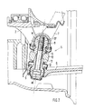
- the wheel suspension 1 comprises an upper link 4 connected to the wheel carrier 2 via a joint 3 - with respect to the wheel axis of rotation R - and a lower link 6 held in a bearing element 5, in which a spring strut 7 is supported with its lower end.
- the bearing element 5 comprises a first standing bearing 8 for the shock absorber 7 and a second hanging bearing 9 for the lower link 6.
- bearings 8 and 9 consist of ball joints and are supported in a ring 10 of the wheel carrier 2.
- the ball joints 8 and 9 have necks 11 and 12, which are tapered and are fitted into corresponding receptacles of the ring 10.
- the ball joints are fastened in the ring 10 by means of a bolt 13, which can be screwed into the standing ball joint 8 with a thread 14 and is supported with its head in the ball joint 9.
- the ball joints 8 and 9 of the bearing element 5 are arranged such that the pivot axis 14 of the wheel 15 through the center axis M of the joint 3 of the upper link 4 and through the center axis of the joints 8 and 9 of the bearing element 5 and the strut runs.
- the pivot axis 14 can only form a small interference lever arm with the distance a due to the joints 3, 8 and 9 which are moved close to the vertical longitudinal plane XX of the wheel center.
- the position of the joints 3, 8 and 9 in the bowl 17 of the rim 16 provides a relatively large support base with the distance b, which results in an optimal damper ratio b / c which is ⁇ 0.9.
- the joint 9 for the lower link 6 is separated in terms of strength from the joint 8 for the spring strut, so that the lower joint is kept free of supporting forces of the spring strut 7 and can therefore be dimensioned more easily and security against failure is ensured.
Landscapes
- Engineering & Computer Science (AREA)
- Mechanical Engineering (AREA)
- Vehicle Body Suspensions (AREA)
- Pivots And Pivotal Connections (AREA)
- Steering-Linkage Mechanisms And Four-Wheel Steering (AREA)
Applications Claiming Priority (2)
| Application Number | Priority Date | Filing Date | Title |
|---|---|---|---|
| DE3938475 | 1989-11-20 | ||
| DE3938475A DE3938475A1 (de) | 1989-11-20 | 1989-11-20 | Radaufhaengung |
Publications (3)
| Publication Number | Publication Date |
|---|---|
| EP0428840A2 true EP0428840A2 (fr) | 1991-05-29 |
| EP0428840A3 EP0428840A3 (en) | 1991-12-04 |
| EP0428840B1 EP0428840B1 (fr) | 1993-11-03 |
Family
ID=6393855
Family Applications (1)
| Application Number | Title | Priority Date | Filing Date |
|---|---|---|---|
| EP90116955A Expired - Lifetime EP0428840B1 (fr) | 1989-11-20 | 1990-09-04 | Suspension de roue |
Country Status (5)
| Country | Link |
|---|---|
| US (1) | US5062655A (fr) |
| EP (1) | EP0428840B1 (fr) |
| JP (1) | JPH03176214A (fr) |
| DE (2) | DE3938475A1 (fr) |
| ES (1) | ES2045697T3 (fr) |
Cited By (1)
| Publication number | Priority date | Publication date | Assignee | Title |
|---|---|---|---|---|
| DE4212696A1 (de) * | 1992-04-16 | 1993-10-21 | Teves Gmbh Alfred | Radaufhängung für Kraftfahrzeuge |
Families Citing this family (20)
| Publication number | Priority date | Publication date | Assignee | Title |
|---|---|---|---|---|
| DE4238577A1 (de) * | 1992-11-16 | 1994-05-19 | Kloeckner Humboldt Deutz Ag | Dichtheitsprüfverfahren und Dichtheitsprüfvorrichtung |
| DE9306932U1 (de) * | 1993-05-07 | 1993-07-08 | Dr.Ing.H.C. F. Porsche Ag, 7000 Stuttgart | Befestigungsvorrichtung |
| CA2140174C (fr) * | 1994-02-07 | 2000-08-22 | Eric G. Parker | Organe de raccord pivotant a embout spherique |
| US5473955A (en) * | 1994-04-04 | 1995-12-12 | Ford Motor Company | Wiper system double ball joint |
| US6338589B1 (en) * | 1998-07-14 | 2002-01-15 | American Axle & Manufacturing, Inc. | Hybrid ball stud |
| DE10038267B4 (de) * | 2000-08-04 | 2009-01-02 | Audi Ag | Vorrichtung zur karosserieseitigen Lagerung eines Federbeines |
| JP4031917B2 (ja) * | 2001-06-20 | 2008-01-09 | 本田技研工業株式会社 | サスペンション構造 |
| US6752410B2 (en) * | 2001-12-28 | 2004-06-22 | Meritor Heavy Vehicle Technology, Llc | Independent suspension for low profile vehicles |
| US20030133744A1 (en) * | 2002-01-15 | 2003-07-17 | Trw Inc. | Ball joint with dual tapered connection |
| US6719312B2 (en) * | 2002-01-22 | 2004-04-13 | Trw Inc. | Steering linkage and ball joint |
| DE10257592A1 (de) * | 2002-12-09 | 2004-07-15 | Valeo Wischersysteme Gmbh | Kugelbolzen und Kugelgelenk mit einem solchen Kugelbolzen |
| DE20313665U1 (de) * | 2003-09-03 | 2004-01-29 | Trw Fahrwerksysteme Gmbh & Co Kg | System zur Wankwinkelverringerung bei Kraftfahrzeugen |
| EP1764042A3 (fr) * | 2005-09-12 | 2009-08-26 | Arthrex, Inc. | Agrafe à compression |
| US7320555B2 (en) * | 2005-10-14 | 2008-01-22 | Sercomm Corporation | Cardan shaft structure with tightness adjustable functions |
| US8240687B2 (en) * | 2007-07-04 | 2012-08-14 | Honda Motor Co., Ltd. | Wheel suspension system for a steerable wheel |
| US8136824B2 (en) * | 2008-08-20 | 2012-03-20 | Agco Corporation | Suspension assemblies with bump steer control |
| DE102012223609A1 (de) * | 2012-12-18 | 2014-06-18 | Zf Friedrichshafen Ag | Gelenkeinrichtung für ein Kraftfahrzeug |
| US11098752B2 (en) * | 2019-06-24 | 2021-08-24 | Federal-Mogul Motorparts Llc | Ball joint with a multi-piece ball stud |
| DE102022200672B4 (de) * | 2022-01-21 | 2025-07-24 | Volkswagen Aktiengesellschaft | Radaufhängung eines Kraftfahrzeugs sowie Kraftfahrzeug mit einer solchen |
| DE102023107011A1 (de) * | 2023-03-21 | 2024-09-26 | Audi Aktiengesellschaft | Radaufhängung für ein Rad einer Achse eines Kraftfahrzeugs sowie Kraftfahrzeug |
Family Cites Families (7)
| Publication number | Priority date | Publication date | Assignee | Title |
|---|---|---|---|---|
| US2123087A (en) * | 1935-07-18 | 1938-07-05 | John W Leighton | Individual wheel suspension |
| GB870789A (en) * | 1959-01-13 | 1961-06-21 | Ustav Pro Vyzkum Motorovych Vo | A motor vehicle front axle assembly |
| DE1405372A1 (de) * | 1959-04-08 | 1968-10-03 | Opel Adam Ag | Radaufhaengung an Kraftfahrzeugen |
| US3061329A (en) * | 1960-06-30 | 1962-10-30 | Ford Motor Co | Vehicle suspension |
| GB921908A (en) * | 1960-12-10 | 1963-03-27 | Tom Edgerton Clarke Hirst | Mechanical linkage joint |
| JPS61278408A (ja) * | 1985-06-03 | 1986-12-09 | Honda Motor Co Ltd | 独立懸架式リヤサスペンシヨン |
| US4810002A (en) * | 1986-07-15 | 1989-03-07 | Nissan Motor Co., Ltd. | Double link type suspension system |
-
1989
- 1989-11-20 DE DE3938475A patent/DE3938475A1/de not_active Withdrawn
-
1990
- 1990-09-04 DE DE90116955T patent/DE59003341D1/de not_active Expired - Fee Related
- 1990-09-04 EP EP90116955A patent/EP0428840B1/fr not_active Expired - Lifetime
- 1990-09-04 ES ES90116955T patent/ES2045697T3/es not_active Expired - Lifetime
- 1990-11-06 US US07/609,635 patent/US5062655A/en not_active Expired - Fee Related
- 1990-11-20 JP JP2313023A patent/JPH03176214A/ja active Pending
Cited By (1)
| Publication number | Priority date | Publication date | Assignee | Title |
|---|---|---|---|---|
| DE4212696A1 (de) * | 1992-04-16 | 1993-10-21 | Teves Gmbh Alfred | Radaufhängung für Kraftfahrzeuge |
Also Published As
| Publication number | Publication date |
|---|---|
| EP0428840B1 (fr) | 1993-11-03 |
| DE3938475A1 (de) | 1991-05-23 |
| US5062655A (en) | 1991-11-05 |
| JPH03176214A (ja) | 1991-07-31 |
| EP0428840A3 (en) | 1991-12-04 |
| ES2045697T3 (es) | 1994-01-16 |
| DE59003341D1 (de) | 1993-12-09 |
Similar Documents
| Publication | Publication Date | Title |
|---|---|---|
| EP0428840A2 (fr) | Suspension de roue | |
| EP0290587B1 (fr) | Suspension indépendante pour un véhicule, particulièrement pour un autobus | |
| DE60008460T2 (de) | Mit einem System zur Steuerung des Radsturzwinkels des Fahrzeugs in Kurven ausgestattetes Kraftfahrzeug | |
| EP0312711B1 (fr) | Suspension de roue pour un véhicule automobile | |
| DE19521875C2 (de) | Achsaufhängung für Starrachsen in Fahrzeugen | |
| DE19903562B4 (de) | Radaufhängung für ein Fahrzeug | |
| EP0291794B1 (fr) | Suspension indépendante des roues directrices pour des véhicules automobiles | |
| EP1076783B1 (fr) | Fixation pour un montant de suspension ou un amortisseur pneumatique d'une suspension de roue | |
| DE2747561A1 (de) | Einzelradaufhaengung fuer kraftfahrzeuge | |
| EP0389685A1 (fr) | Suspension de roue pour les roues avant d'une voiture automobile | |
| EP0494394B1 (fr) | Suspension de roue indépendante pour véhicules automobiles | |
| DE1430850B1 (de) | Lagerung eines zur Fuehrung eines Kraftfahrzeugrades dienenden Querlenkers | |
| DE3782569T2 (de) | Radaufhaengung. | |
| EP0365516B1 (fr) | Guidage des roues pour roues directives pouvant entraîner un véhicule automobile | |
| DE4342809A1 (de) | Verfahren und Anordnung zur Befestigung eines federnd auf einem Fahrzeugrahmen gelagerten Fahrerhauses | |
| DE2820585A1 (de) | Unabhaengige aufhaengung der gelenkten vorderraeder von kraftfahrzeugen | |
| DE202017100164U1 (de) | Hinterradaufhängung für Kraftfahrzeuge | |
| DE1864224U (de) | Oelpneumatische aufhaengung fuer kraftfahrzeuge. | |
| DE19615207C1 (de) | Hilfsrahmen | |
| DE69713696T2 (de) | Aufhängungsvorrichtung, insbesondere für Kraftfahrzeuge | |
| DE2507071B2 (de) | Obere lagerung eines einen radachsschenkel tragenden teleskopstossdaempfers fuer kraftfahrzeuge | |
| DE69325134T2 (de) | Hinterradaufhängung für Kraftfahrzeug mit unabhängigen Rädern | |
| DE4426881C2 (de) | Lenkbare Radaufhängung | |
| DE19960457A1 (de) | Lagerung für ein Dämpferbein oder eine Luftfeder einer Radaufhängung | |
| DE4125300C2 (de) | Lenkeinrichtung |
Legal Events
| Date | Code | Title | Description |
|---|---|---|---|
| PUAI | Public reference made under article 153(3) epc to a published international application that has entered the european phase |
Free format text: ORIGINAL CODE: 0009012 |
|
| AK | Designated contracting states |
Kind code of ref document: A2 Designated state(s): DE ES FR GB IT |
|
| PUAL | Search report despatched |
Free format text: ORIGINAL CODE: 0009013 |
|
| AK | Designated contracting states |
Kind code of ref document: A3 Designated state(s): DE ES FR GB IT |
|
| 17P | Request for examination filed |
Effective date: 19920414 |
|
| 17Q | First examination report despatched |
Effective date: 19930322 |
|
| ITF | It: translation for a ep patent filed | ||
| GRAA | (expected) grant |
Free format text: ORIGINAL CODE: 0009210 |
|
| AK | Designated contracting states |
Kind code of ref document: B1 Designated state(s): DE ES FR GB IT |
|
| REF | Corresponds to: |
Ref document number: 59003341 Country of ref document: DE Date of ref document: 19931209 |
|
| ET | Fr: translation filed | ||
| GBT | Gb: translation of ep patent filed (gb section 77(6)(a)/1977) |
Effective date: 19931208 |
|
| REG | Reference to a national code |
Ref country code: ES Ref legal event code: FG2A Ref document number: 2045697 Country of ref document: ES Kind code of ref document: T3 |
|
| PLBE | No opposition filed within time limit |
Free format text: ORIGINAL CODE: 0009261 |
|
| STAA | Information on the status of an ep patent application or granted ep patent |
Free format text: STATUS: NO OPPOSITION FILED WITHIN TIME LIMIT |
|
| PG25 | Lapsed in a contracting state [announced via postgrant information from national office to epo] |
Ref country code: ES Free format text: LAPSE BECAUSE OF EXPIRATION OF PROTECTION Effective date: 19940905 |
|
| 26N | No opposition filed | ||
| PGFP | Annual fee paid to national office [announced via postgrant information from national office to epo] |
Ref country code: FR Payment date: 19950927 Year of fee payment: 6 |
|
| PGFP | Annual fee paid to national office [announced via postgrant information from national office to epo] |
Ref country code: GB Payment date: 19960918 Year of fee payment: 7 |
|
| PGFP | Annual fee paid to national office [announced via postgrant information from national office to epo] |
Ref country code: DE Payment date: 19960926 Year of fee payment: 7 |
|
| PG25 | Lapsed in a contracting state [announced via postgrant information from national office to epo] |
Ref country code: FR Effective date: 19960930 |
|
| REG | Reference to a national code |
Ref country code: FR Ref legal event code: ST |
|
| REG | Reference to a national code |
Ref country code: FR Ref legal event code: ST |
|
| PG25 | Lapsed in a contracting state [announced via postgrant information from national office to epo] |
Ref country code: GB Free format text: LAPSE BECAUSE OF NON-PAYMENT OF DUE FEES Effective date: 19970904 |
|
| GBPC | Gb: european patent ceased through non-payment of renewal fee |
Effective date: 19970904 |
|
| PG25 | Lapsed in a contracting state [announced via postgrant information from national office to epo] |
Ref country code: DE Free format text: LAPSE BECAUSE OF NON-PAYMENT OF DUE FEES Effective date: 19980603 |
|
| REG | Reference to a national code |
Ref country code: ES Ref legal event code: FD2A Effective date: 19990601 |
|
| PG25 | Lapsed in a contracting state [announced via postgrant information from national office to epo] |
Ref country code: IT Free format text: LAPSE BECAUSE OF NON-PAYMENT OF DUE FEES;WARNING: LAPSES OF ITALIAN PATENTS WITH EFFECTIVE DATE BEFORE 2007 MAY HAVE OCCURRED AT ANY TIME BEFORE 2007. THE CORRECT EFFECTIVE DATE MAY BE DIFFERENT FROM THE ONE RECORDED. Effective date: 20050904 |