EP0428873A2 - Verfahren und Apparat zum Regulieren des Gasgehaltes in einem Schaummaterial - Google Patents
Verfahren und Apparat zum Regulieren des Gasgehaltes in einem Schaummaterial Download PDFInfo
- Publication number
- EP0428873A2 EP0428873A2 EP90120168A EP90120168A EP0428873A2 EP 0428873 A2 EP0428873 A2 EP 0428873A2 EP 90120168 A EP90120168 A EP 90120168A EP 90120168 A EP90120168 A EP 90120168A EP 0428873 A2 EP0428873 A2 EP 0428873A2
- Authority
- EP
- European Patent Office
- Prior art keywords
- gas
- amount
- liquid material
- flow
- mixer
- Prior art date
- Legal status (The legal status is an assumption and is not a legal conclusion. Google has not performed a legal analysis and makes no representation as to the accuracy of the status listed.)
- Granted
Links
Images
Classifications
-
- G—PHYSICS
- G05—CONTROLLING; REGULATING
- G05D—SYSTEMS FOR CONTROLLING OR REGULATING NON-ELECTRIC VARIABLES
- G05D11/00—Control of flow ratio
- G05D11/02—Controlling ratio of two or more flows of fluid or fluent material
- G05D11/13—Controlling ratio of two or more flows of fluid or fluent material characterised by the use of electric means
-
- B—PERFORMING OPERATIONS; TRANSPORTING
- B29—WORKING OF PLASTICS; WORKING OF SUBSTANCES IN A PLASTIC STATE IN GENERAL
- B29B—PREPARATION OR PRETREATMENT OF THE MATERIAL TO BE SHAPED; MAKING GRANULES OR PREFORMS; RECOVERY OF PLASTICS OR OTHER CONSTITUENTS OF WASTE MATERIAL CONTAINING PLASTICS
- B29B7/00—Mixing; Kneading
- B29B7/30—Mixing; Kneading continuous, with mechanical mixing or kneading devices
- B29B7/58—Component parts, details or accessories; Auxiliary operations
- B29B7/72—Measuring, controlling or regulating
-
- G—PHYSICS
- G05—CONTROLLING; REGULATING
- G05D—SYSTEMS FOR CONTROLLING OR REGULATING NON-ELECTRIC VARIABLES
- G05D11/00—Control of flow ratio
- G05D11/02—Controlling ratio of two or more flows of fluid or fluent material
- G05D11/13—Controlling ratio of two or more flows of fluid or fluent material characterised by the use of electric means
- G05D11/131—Controlling ratio of two or more flows of fluid or fluent material characterised by the use of electric means by measuring the values related to the quantity of the individual components
- G05D11/132—Controlling ratio of two or more flows of fluid or fluent material characterised by the use of electric means by measuring the values related to the quantity of the individual components by controlling the flow of the individual components
-
- Y—GENERAL TAGGING OF NEW TECHNOLOGICAL DEVELOPMENTS; GENERAL TAGGING OF CROSS-SECTIONAL TECHNOLOGIES SPANNING OVER SEVERAL SECTIONS OF THE IPC; TECHNICAL SUBJECTS COVERED BY FORMER USPC CROSS-REFERENCE ART COLLECTIONS [XRACs] AND DIGESTS
- Y10—TECHNICAL SUBJECTS COVERED BY FORMER USPC
- Y10S—TECHNICAL SUBJECTS COVERED BY FORMER USPC CROSS-REFERENCE ART COLLECTIONS [XRACs] AND DIGESTS
- Y10S261/00—Gas and liquid contact apparatus
- Y10S261/26—Foam
Definitions
- the present invention relates to foam material dispensing systems and, more particularly, to systems for mixing gas and high viscosity liquid materials under pressure and dispensing the mixed material to form a foam, and to methods and apparatus for controlling the gas-to-material ratio of the dispensed foam.
- Foam materials are used in a variety of applications where their bonding strength, resiliency, property retention and other characteristics are desired.
- a number of liquid materials such as liquid adhesives, sealants, and other such high viscosity materials attain enhanced properties when employed in the form of a foam.
- Foam adhesives for example, have extensive use in the packaging fields and for the assembly of certain products. They are particularly suitable for use on packaging or production lines. Foam adhesive systems and devices for such systems are shown in detail in U.S. Pat. Nos.
- Foam sealants or caulks may, for example, be provided by injecting air, or preferably an oxygen-free gas such as nitrogen, into the material prior to delivery to the dispensing device.
- the materials used for foam sealants or caulks are typically substances having medium to high viscosity, often formed from bulk material which is supplied to the material is sometimes moderately such a system, the material is sometimes moderately heated to enhance its flow and setting properties, and is sometimes heated to higher temperatures to produce a hot-melt flowable material from a solid thermoplastic material supplied in bulk to the system.
- the foam material is formulated in a foam material dispensing system by mixing the liquid material with compressed gas before it is dispensed in foamable form, as, for example, before dispensing an adhesive onto a part.
- the gas and the material are maintained under pressure so that the gas, which may be approximately 1/10th of one percent by weight of the adhesive mixture, is dissolved or otherwise contained in the mixture such that there is no more than a negligible change in volume from that of the material alone.
- the gas in the mixture expands producing a foamed material of a density which has been reduced by the increased volume of the added expanded gas.
- the foaming of the material such that it will have a desired density when expanded at standard temperature and pressure requires a precise concentration of foaming agent in the mix.
- a gas-to-sealant ratio is desired which will produce a volume of gas which is approximately of the same order of magnitude as the volume of sealant in the foam sealant mix.
- the mass ratio of the gas to the sealant would be of the order of one thousand to one. Accordingly, monitoring and controlling the amount of gas in the mixed material is difficult in that very small deviations in the mass of the solution can produce large errors in the desired density of the material when it foams at atmospheric pressure.
- the gas-to-material ratio of such foamed materials may be attained by adding the density reducing gas at a controlled mass flow rate into a mixer in which there is injected a measured volume flow of the material.
- ratios have been maintained by controls which measure parameters of the mixed foam adhesive to generate a feedback signal with which to vary the settings of flow control devices to adjust the relative amounts of gas and hot-melt fed to the mixer, as for example, are shown in the commonly assigned U.S. Pat. No. 4,779,762 to Klein et al., hereby expressly incorporated herein by reference. Because the mixed adhesive in hot-melt systems is usually of only moderate viscosity, recirculation of a major portion of the mixed adhesive from a discharge gun back to the mixer enhances the ability of a hot-melt system to maintain the gas concentration of the mix uniform where the corrective gas flow may not immediately follow that of the sealant into the mixer.
- the flow of the blowing-agent or gas in such systems is, on the other hand, more suitably achieved by a mas flow meter which, since the gas is highly compressible, produces a more accurate means of determining the volume at standard temperature and pressure than do devices which measure gas volume directly.
- These mass flow meters typically generate analog signals representing mass flow of the gas through the meter per unit time. Integration of such an analog signal over time provides a measurement of the total mass of injected gas. This mass measurement is convertible to a volume equivalent at a given temperature and pressure by simple computation.
- one transducer Since one transducer generates a digital signal representing an amount measured in discrete quanta and the other generates an analog signal proportional to a flow of gas per unit time, a direct comparison is not possible.
- this problem has been solved by converting the square wave signal to an analog signal with the use of a tachometer or frequency-to-voltage converter.
- the resulting analog signal then represents a liquid material flow per unit time which can be directly compared with the analog signal from the gas flow meter to determine the ratio at which the liquid material and the gas are being injected to the mixer to produce the ratio that is desired.
- Conversion of the digital signal by using a tachometer type device may be acceptable in some cases where the process is continuous, or, where the material flow on-time is large compared with the dwell time or off-time of the liquid material flow meter.
- errors will, however, develop at the times immediately following flow startups, flow stops, or rapid flow rate changes.
- Such errors are a result of time constants necessary to convert a digital signal to an analog signal and other time delays inherent in the components of the system.
- the time constants are necessary to covert a pulse rate signal to an analog signal which is suitable for use in controlling the flow of the injected gas in a stable manner.
- Such time constants or damping factors are necessary to minimize output ripple during normal operation. Reducing such ripple, however, ultimately increases response time.
- the tachometer will integrate and average the digital signal over time and generate an output signal which will increase continuously from zero to a constant output value.
- This signal when scaled by conversion factors including one representing a setting of the ratio of the gas to the liquid material, will represent the current desired flow rate of the gas.
- the scaled signal is used to control a gas flow control valve which controls the flow rate of the gas into the mix.
- the output of the tachometer When liquid flow to the mixer terminates, the output of the tachometer will similarly not immediately decline to zero, but will decay in a continuous manner to a zero output value. Delays in the output signal response thus occur at the beginning and end of the liquid flow. These delays result in errors in the flow of gas to the mixer. The errors which occur at the startup of the flow do not necessarily cancel the errors which occur at the termination of the flow. For these reasons, the prior art systems fail to accurately control the flow rate of the gas.
- a signal proportional to the flow of high viscosity liquid material in a foam dispensing system is generated and information representing the cumulative amount of gas needed to maintain the gas concentration of the dispensed foamed is collected.
- the collected information is reduced only by the flow of gas actually mixed with the liquid material to be foamed. The difference remaining is used to generate a control signal, according to the desired gas-to-liquid ratio of the mix, to control the flow of gas into the mix.
- a foamed adhesive and sealant material is produced by mixing pressurized gas with a high viscosity liquid material in a predetermined gas-to-liquid ratio.
- the flow of liquid is precisely measured and the measured liquid flow value is accumulated. From the accumulated value, the total gas needed to maintain the ratio derived.
- the amount of gas injected into the mix is also measured and that measurement substracted from the total amount needed to maintain the correct gas-to-liquid ratio.
- the difference becomes an error signal which is stored.
- the error signal represents the cumulative difference between the computed amount of gas required to produce the desired ratio given the measured amount of liquid and measured amount of gas actually injected into the mixer.
- Injection of the gas is controlled in response to the cumulative error signal so that any delay in the response of the view of the gas to the control signal will continue to influence the control signal so as to call for additional gas flow to the mixer until the error is eliminated and the desired ratio is attained.
- the gain or sensitivity of the control signal to the error signal is such that the system responds quickly, yet in a stable manner, to inject the gas needed to reduce or eliminate the stored error.
- control signal to the gas flow control valve is an analog signal having a magnitude which varies in relation to both the current flow rate of liquid material and the magnitude of the cumulative error term.
- the amount of the liquid material which flows into a mixer during each interval of time is directly measured using a digital flow meter which generates a square-wave output signal, each pulse of which represents the same fixed amount of the liquid material, as for example liquid sealant, to a mixer.
- These pulses are counted and the count multiplied by the desired ratio to produce a value proportional to the amount of gas to be injected into the mixer to maintain the desired gas-to-liquid ratio for the measured incremental amount of sealant flow measured during the interval.
- the actual amount of gas to flow into the mixer during the corresponding time interval is also measured and subtracted from the computed desired amount of gas which should be injected.
- the difference is then added to an error term so as to accumulate, or integrate, the difference so that it represents the total gas which is still to be injected into the mixer to properly dilute the injected liquid material.
- the error term is, accordingly, the stored value representing the total amount of gas required to produce a foamed adhesive sealant from the measured total amount of liquid material which has been delivered to the mixer.
- the error term is only reduced by an amount equal to the actual amount of gas delivered to the mixer.
- pulses from the flow meter are counted and stored so that each pulse can be thereafter acted upon.
- the controller will ultimately inject the appropriate mass of gas, which, when at standard temperature and pressure, will match the volume of the unit of liquid material represented by the digital puse. Any difference between the amount of gas required to be injected and the amount of gas actually injected is accumulated as an error term which continually influences the control signal to the gas injector control valve until all of the gas required to reduce the error has been injected. By this method, regardless of the rate of delivery, the eventual error will thus be zero.
- a single pulse from the flow meter represents a fixed volume of liquid.
- a corresponding fixed volume of gas at standard temperature and pressure
- the controller supplies the full amount of gas required before the next pulse is generated representing the injection of another increment of liquid into the mixer, the new solution in the mixer will have the same density reduction as the material that just left the mixer.
- the gas is injected at a rate which will tend to quickly reduce errors which occur, the back mixing will cause a substantially uniform density adhesive to be maintained.
- Small, intermittently applied flows which plagued the prior art systems do not pose a problem with the controller of the present invention.
- the present invention provides the advantage of a uniform gas-to-liquid material ratio, or uniform gas concentration, in a foam material dispensing operation in which the flow rate varies or switches on and off rapidly.
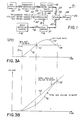
- a foam adhesive mixing and dispensing system 10 is illustrated.
- This illustrated embodiment presents a typical system in which a high viscosity liquid sealant and adhesive material is mixed at high pressure with a gas at a predetermined ratio to produce and dispense upon a part a foamed adhesive sealant of a desired gas concentration or material density.
- the system 10 for which the present invention is most beneficial is the high viscosity polymer adhesive material dispensing system of the type disclosed in Cobbs U.S. Pat. No. 4,778,631 incorporated by reference above.
- the invention also may be used with advantage in heated or hot-melt foam material dispensing systems and in systems with external recirculating loops for the foamable mixed pressurized material such as disclosed in Klein U.S. Pat. No.
- the system 10 includes a supply of bulk adhesive sealant material 12 from which the material is provided in highly viscous form to an output hose or pipe 14 which directs the liquid sealant material through a digital flow meter 16.
- the meter 16 produces output pulses on a signal line 18 to a controller 20.
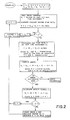
- the controller 20 is a microprocessor based device programmed to function in accordance with the flow chart of Fig. 2 and corresponding description set forth below.
- the output pulses each represent a fixed incremental volume of sealant flowing through the meter 16, and from there through line 21 to a mixer 24.
- the sealant is mixed with a gas, preferably nitrogen.
- the gas is injected through a gas line 25 into the mixer 24 where it is mixed with the sealant to produce a pressurized foamable sealant adhesive material.
- the foam adhesive so mixed is delivered to a dispensing gun 26 to which it is connected through a hose 28.
- the gas, or blowing agent is supplied from a pressurized gas source or supply 40 through the line 41 and pressure regulator 42 through the line 43 to the input of a mass flow meter 45.
- the gas within the system 10 from the supply 40 to the gun 26 is maintained under sufficient pressure to essentially dissolve the gas in the sealant from the mixer 24 to the gun 26. As such, the gas will only contribute to approximately 1/1000th of the mass of the mix prior to release from the gun 26.
- the flowmeter 45 measures the mass of gas flowing into the mixer 24 and also controls the flow of the gas therethrough.
- the flowmeter 45 has an outlet connected to the gas inlet line 25 to the mixer 24.
- the flow meter 45 produces an analog output signal proportional to the gas flow rate through the flow meter 45 on a signal line 47 which is connected to an analog signal input of the controller 20.
- the controller 20 produces an analog output signal on an output line 48 to the flow meter 45.
- the flow meter contains a servo-valve which is responsive to the analog input signal on line 48 from the controller 20 to vary the gas injected on line 25 to the mixer 24 in accordance with the logic of the controller 20, described below.
- the controller 20 has a set of inputs 50 which accept settings from the operator which include a setting for the programmed ratio of gas to sealant, preferably in volume percentage of the gas to the total mixture corrected to standard temperature and pressure.
- the controller 20 also has a sealant meter range setting and a gas meter range setting.
- the operation of the system 10 proceeds with a piston pump (not shown) in the bulk sealant source 12 supplying sealant at constant pressure on the line 14 to the flow meter 16.
- nitrogen or other suitable gas from the supply 40 is supplied at constant pressure at the outlet 43 of the regulator 42 to the gas flow meter 45.
- the sealant is supplied further at constant pressure to through the inlet line 21 of the mixer 24.
- the sealant flow is affected by the demand for sealant at the mixer 24 which results when adhesive is dispensed from the gun 26 in response to a programmed robot controller (not shown) of the dispensing system.
- the amount of gas, however, which is delivered at the inlet 25 of the mixer 24 is controlled by the operation of the servo-valve of the gas meter 45 in response to the control signal on the line 48 from the controller 20.
- the operation of the system 10 proceeds with the system demanding the adhesive from the gun 26 by a control signal which opens the gun 26 to dispense mixed adhesive foam.
- the dispensing of the adhesive causes additional make-up sealant to flow through the meter 16 and into the mixer 24 by way of the line 21.
- the flow of sealant through the meter 16 causes a series of pulses to be output by the flow meter 16 on the line 18 to the controller 20, each pulse representing a fixed incremental volume of sealant flow through the meter 16.
- the controller responds by reading the analog signal on the analog input line 47 from the gas flow meter 45 to determine the amount, if any, of gas which has flowed through the meter 45.
- the controller then generates, in response to the accumulated signals on lines 18 and 47, a control signal on the controller output line 48 to the valve of the meter 45.
- the valve of the meter 45 operates in response to the signal on line 48 to cause a flow of gas to occur, at a rate responsive to the control signal, on the line 25 to the mixer 24.
- the gas is mixed with the sealant flowing into the mixer from the line 21. This mixture is recirculated within the mixer 24 so that it achieves a uniform density at the ratio which has been programmed.
- the operation of the controller 20 is represented by the flowchart of Fig. 2.
- the controller stores values for certain constants for use by the control logic. These values include the timer interval T (preferably equal to 1/2 second) which determines the frequency of the flow measurements taken by the meters 16 and 45, the gas ratio setting R of the adhesive (for example 50%), the flow rate conversion constant C (representing the sealant flow in cubic centimeters per pulse from the sealant flow meter 16), and the gain A of the control signal equation discussed below.
- H I represents the current flow rate signalled on the line 47 from the flow meter 45
- H I-1 represents the flow rate measured on the line 47 at the previous measurement made a time increment T in the past.
- E I and F I represent the computed error and control signals at the end of the interval I while E I-1 and F I-1 represent the respective values of E and F computed at a time increment T in the past.
- the variable S has 60 values each representing a measurement of sealant flow S I-59 through S I at the sixty time intervals ending with the current time interval I.
- the flow G is in cc./min., and of the same scale as the signal W which represents sealant flow rate.
- E I E I-1 + (R ⁇ S I C) - (G ⁇ T), where T equals the time duration of the interval I, or preferably 1/120th minute, and C equals the sealant volume per pulse from the sealant flow meter 16. If the error is unacceptable, then the program will enter an error processing mode. Otherwise, it will proceed to calculate the value of the control signal to be output from the controller 20 to the valve of the gas meter 45.
- the calculation of the control signal is made by multiplying the sealant flow rate W by the ratio setting R and adding to it the error term E I multiplied by a gain factor A which, in the preferred embodiment using the values set forth above, preferably equals 6.
- control signal calculated according to the formula is less than zero, it is set to zero. Otherwise, the value of the control signal F I is checked against a predetermined limit imposed on the rate of change of the signal F for stability of the control operation. The limit is selected in accordance with the response time of the valve of the gas flow meter 45. If the change (F I - F I-1 ) is greater than the rate of change which the servo valve of the meter 45 can track, then F I is increased or decreased only in the maximum amount which the valve can flow.
- the minimum value of F I which is output to the gas valve will always be set to at least 2% of the full scale signal to which the valve of meter 45 will respond, unless a zero value of F I is required, in which case a zero value is sent to the value of the meter 45.
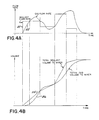
- Figs. 3A and 3B and Figs. 4A and 4B The performance of the system according to the preferred embodiment of the invention is illustrated by the calculated examples of Figs. 3A and 3B and Figs. 4A and 4B.
- the density reduction ratio is taken as 50%, or an equal volume of sealant and gas (at standard temperature and pressure), in order to best illustrate the operation of the control. It will be appreciated, however, from the description below that in the general case, the curves representing sealant on Figs. 3A, 3B, 4A and 4B will be scaled differently than those representing gas.
- Figs. 4A and 4B represent the case of constant sealant flow following a startup form a zero flow rate of sealant.
- the sealant flow is shown to step instantaneously from zero to a value represented by the line 71.
- Such a sealant flow will cause the sealant flow meter 16 to generate a continuous stream of regularly spaced pulses on the line 18 to the controller 20.
- the error term E I accumulates a value equal to the amount of sealant which passed through the meter 16 to be reduced only by the amount of gas (G ⁇ T) to be measured by the gas flow meter 45.
- a control signal F I will be sent to the valve of gas meter 45. This signal will cause an increasing flow of gas at a rate G to flow through the meter 45 as represented by the line 72 on the graph of Fig. 3A.
- the area between the curves 71 and 72 represents the accumulated difference between the sealant flow and gas flow to the mixer 24.
- the ratio will be sealant rich. This condition is represented by the inequality of the values of the curves 75 and 76 in Fig. 3B which represent the cumulative sealant flow and cumulative gas flow, respectively.
- FIGs. 4A and 4B show the approach of the gas flow to that of the sealant flow to the mixer 24 in response to a plurality of changes in the sealant flow rate.
Landscapes
- Engineering & Computer Science (AREA)
- Physics & Mathematics (AREA)
- General Physics & Mathematics (AREA)
- Automation & Control Theory (AREA)
- Mechanical Engineering (AREA)
- Accessories For Mixers (AREA)
- Processing And Handling Of Plastics And Other Materials For Molding In General (AREA)
- Nozzles (AREA)
- Coating Apparatus (AREA)
- Manufacture Of Porous Articles, And Recovery And Treatment Of Waste Products (AREA)
Applications Claiming Priority (2)
| Application Number | Priority Date | Filing Date | Title |
|---|---|---|---|
| US07/439,251 US5056034A (en) | 1989-11-20 | 1989-11-20 | Method and apparatus for controlling the gas content of foam materials |
| US439251 | 1989-11-20 |
Publications (3)
| Publication Number | Publication Date |
|---|---|
| EP0428873A2 true EP0428873A2 (de) | 1991-05-29 |
| EP0428873A3 EP0428873A3 (en) | 1992-10-07 |
| EP0428873B1 EP0428873B1 (de) | 1996-04-24 |
Family
ID=23743948
Family Applications (1)
| Application Number | Title | Priority Date | Filing Date |
|---|---|---|---|
| EP90120168A Expired - Lifetime EP0428873B1 (de) | 1989-11-20 | 1990-10-20 | Verfahren und Apparat zum Regulieren des Gasgehaltes in einem Schaummaterial |
Country Status (9)
| Country | Link |
|---|---|
| US (1) | US5056034A (de) |
| EP (1) | EP0428873B1 (de) |
| JP (1) | JP3133320B2 (de) |
| KR (1) | KR0169310B1 (de) |
| BR (1) | BR9005842A (de) |
| CA (1) | CA2027384C (de) |
| DE (1) | DE69026683T2 (de) |
| DK (1) | DK0428873T3 (de) |
| ES (1) | ES2087878T3 (de) |
Cited By (3)
| Publication number | Priority date | Publication date | Assignee | Title |
|---|---|---|---|---|
| EP0605138A1 (de) * | 1992-12-30 | 1994-07-06 | Nordson Corporation | Abgabesystem für Beschichtungsmaterial, welches einen Katalysator enthält |
| EP2272648A1 (de) * | 2007-02-16 | 2011-01-12 | Nordson Corporation | Vorrichtung und Verfahren zum Ausgeben einer Mischung aus Gas und Flüssigkeit |
| CN110944815A (zh) * | 2017-08-31 | 2020-03-31 | 三菱重工机械系统株式会社 | 监视装置、监视方法及程序 |
Families Citing this family (25)
| Publication number | Priority date | Publication date | Assignee | Title |
|---|---|---|---|---|
| US5426593A (en) * | 1991-02-19 | 1995-06-20 | Seiden; Louis W. | Gas content measurement |
| US5389168A (en) * | 1993-06-30 | 1995-02-14 | The Procter & Gamble Company | Method of making an elastomeric adhesive foam and of elasticizing garments |
| US5342858A (en) * | 1993-06-30 | 1994-08-30 | The Procter & Gamble Company | Elastomeric adhesive foam |
| US5480589A (en) | 1994-09-27 | 1996-01-02 | Nordson Corporation | Method and apparatus for producing closed cell foam |
| US5472990A (en) * | 1994-11-10 | 1995-12-05 | Dennis Chemical Co., Inc. | Method and apparatus for nucleation of polyurethane foam which results in self-adhering microcellular foam |
| US6280692B1 (en) * | 1996-08-02 | 2001-08-28 | Blentek Systems, Inc. | Open-loop apparatus for producing a controlled blend of polyol and blowing agent for use in the manufacture of polyurethane foam |
| US6819783B2 (en) | 1996-09-04 | 2004-11-16 | Centerframe, Llc | Obtaining person-specific images in a public venue |
| SE9901336L (sv) * | 1999-04-15 | 2000-06-12 | Haegglund Konsult Ab | Reglersystem och förfarande för kvotstyrning jämte användning av ett reglersystem |
| US6729695B2 (en) | 2001-06-12 | 2004-05-04 | Lacks Industries, Inc. | Vehicle wheel assembly and related method therefor cross-references to related applications |
| US6708573B1 (en) * | 2002-09-12 | 2004-03-23 | Air Products And Chemicals, Inc. | Process for filling compressed gas fuel dispensers which utilizes volume and density calculations |
| US20040072450A1 (en) * | 2002-10-15 | 2004-04-15 | Collins Jimmy D. | Spin-coating methods and apparatuses for spin-coating, including pressure sensor |
| US6807849B1 (en) * | 2002-10-28 | 2004-10-26 | The University Of Tulsa | Foam generator and viscometer apparatus and process |
| US20050058016A1 (en) * | 2003-09-15 | 2005-03-17 | Smith Morris E. | Method to blend two or more fluids |
| US20050094482A1 (en) * | 2003-10-31 | 2005-05-05 | Nordson Corporation | Method and apparatus for producing closed cell foam |
| US7231805B2 (en) * | 2004-11-03 | 2007-06-19 | Nordson Corporation | Bubble detection with temperature compensation |
| WO2006091869A2 (en) | 2005-02-25 | 2006-08-31 | Youfinder Intellectual Property Licensing Limited Liability Company | Automated indexing for distributing event photography |
| DE102005042380A1 (de) * | 2005-09-06 | 2007-03-08 | Nordson Corporation, Westlake | Vorrichtung und Verfahren zum Erzeugen eines Schaummaterials |
| US20090236025A1 (en) * | 2008-03-24 | 2009-09-24 | Nordson Corporation | Apparatus and methods for producing foamed materials |
| US8332281B2 (en) | 2009-09-02 | 2012-12-11 | Image Holdings | Method of displaying, managing and selling images in an event photography environment |
| US8392268B2 (en) | 2009-09-02 | 2013-03-05 | Image Holdings | Method and system of displaying, managing and selling images in an event photography environment |
| DE102011117836A1 (de) * | 2011-11-08 | 2013-05-08 | Focke & Co. (Gmbh & Co. Kg) | Ventil, insbesondere Leimventil |
| DE102012003278A1 (de) * | 2012-02-20 | 2013-08-22 | Bürkert Werke GmbH | Gasmischer |
| US10058825B2 (en) * | 2014-12-12 | 2018-08-28 | Nordson Corporation | Foam mixing system and methods |
| US11305978B2 (en) | 2018-08-13 | 2022-04-19 | Carlisle Fluid Technologies, Inc. | Modular plural component platform |
| WO2021131054A1 (ja) * | 2019-12-27 | 2021-07-01 | サンスター技研株式会社 | ガス供給システム、機械発泡システム及びガスを供給する方法 |
Family Cites Families (12)
| Publication number | Priority date | Publication date | Assignee | Title |
|---|---|---|---|---|
| FR1346168A (fr) * | 1963-02-01 | 1963-12-13 | Dehavilland Aircraft | Perfectionnements à un procédé et à un appareil de mélange de fluides |
| US4038534A (en) * | 1975-02-27 | 1977-07-26 | Mohammad Kian Mirdadian | Methods and systems for use with pulse train circuitry |
| US4059714A (en) * | 1976-08-02 | 1977-11-22 | Nordson Corporation | Hot melt thermoplastic adhesive foam system |
| US4059466A (en) * | 1976-08-02 | 1977-11-22 | Nordson Corporation | Hot melt thermoplastic adhesive foam system |
| DE2724132C3 (de) * | 1977-05-27 | 1980-09-25 | Bayer Ag, 5090 Leverkusen | Verfahren und Vorrichtung zum Herstellen eines schaumstoffbildenden Reaktionsgemisches |
| US4200207A (en) * | 1978-02-01 | 1980-04-29 | Nordson Corporation | Hot melt adhesive foam pump system |
| DE2933327A1 (de) * | 1979-08-17 | 1981-03-26 | Bayer Ag, 51373 Leverkusen | Verfahren und einrichtung zum herstellen eines massiv- oder schaumstoff bildenden fliessfaehigen reaktionsgemisches |
| FR2548549B1 (fr) * | 1983-07-08 | 1988-09-23 | Asm Sud Europe | Melangeur de gaz a usage medical |
| US4779762A (en) * | 1984-05-30 | 1988-10-25 | Nordson Corporation | Method and apparatus for controlling the gas content of dispensed hot melt thermoplastic adhesive foam |
| US4778631A (en) * | 1985-10-02 | 1988-10-18 | Nordson Corporation | Method and apparatus for foaming high viscosity polymer materials |
| CH674096A5 (de) * | 1988-01-19 | 1990-04-30 | Lonza Ag | |
| US4924695A (en) * | 1988-12-08 | 1990-05-15 | Atlantic Richfield Company | Apparatus for compressing a fluid sample to determine gas content and the fraction of one liquid composition in another |
-
1989
- 1989-11-20 US US07/439,251 patent/US5056034A/en not_active Expired - Lifetime
-
1990
- 1990-10-11 CA CA002027384A patent/CA2027384C/en not_active Expired - Fee Related
- 1990-10-20 DE DE69026683T patent/DE69026683T2/de not_active Expired - Fee Related
- 1990-10-20 ES ES90120168T patent/ES2087878T3/es not_active Expired - Lifetime
- 1990-10-20 DK DK90120168.1T patent/DK0428873T3/da active
- 1990-10-20 EP EP90120168A patent/EP0428873B1/de not_active Expired - Lifetime
- 1990-11-19 BR BR909005842A patent/BR9005842A/pt not_active IP Right Cessation
- 1990-11-19 KR KR1019900018698A patent/KR0169310B1/ko not_active Expired - Fee Related
- 1990-11-20 JP JP02315263A patent/JP3133320B2/ja not_active Expired - Fee Related
Cited By (5)
| Publication number | Priority date | Publication date | Assignee | Title |
|---|---|---|---|---|
| EP0605138A1 (de) * | 1992-12-30 | 1994-07-06 | Nordson Corporation | Abgabesystem für Beschichtungsmaterial, welches einen Katalysator enthält |
| US5490726A (en) * | 1992-12-30 | 1996-02-13 | Nordson Corporation | Apparatus for proportioning two components to form a mixture |
| EP2272648A1 (de) * | 2007-02-16 | 2011-01-12 | Nordson Corporation | Vorrichtung und Verfahren zum Ausgeben einer Mischung aus Gas und Flüssigkeit |
| US9038921B2 (en) | 2007-02-16 | 2015-05-26 | Nordson Corporation | Apparatus and method for dispensing a mixture of a gas and a fluid material |
| CN110944815A (zh) * | 2017-08-31 | 2020-03-31 | 三菱重工机械系统株式会社 | 监视装置、监视方法及程序 |
Also Published As
| Publication number | Publication date |
|---|---|
| CA2027384C (en) | 1999-11-16 |
| DE69026683D1 (de) | 1996-05-30 |
| DE69026683T2 (de) | 1996-09-19 |
| KR0169310B1 (ko) | 1999-03-20 |
| JPH03181350A (ja) | 1991-08-07 |
| ES2087878T3 (es) | 1996-08-01 |
| BR9005842A (pt) | 1991-09-24 |
| CA2027384A1 (en) | 1991-05-21 |
| EP0428873A3 (en) | 1992-10-07 |
| DK0428873T3 (da) | 1996-06-17 |
| EP0428873B1 (de) | 1996-04-24 |
| JP3133320B2 (ja) | 2001-02-05 |
| US5056034A (en) | 1991-10-08 |
| KR910010115A (ko) | 1991-06-28 |
Similar Documents
| Publication | Publication Date | Title |
|---|---|---|
| EP0428873B1 (de) | Verfahren und Apparat zum Regulieren des Gasgehaltes in einem Schaummaterial | |
| EP0494453B1 (de) | Verfahren und Vorrichtung zur Messung des Materialflusses in einer Zweikomponenten-Abgabevorrichtung | |
| EP1658145B1 (de) | Steuerung und system zur abgabe von fluidmaterial | |
| JP3192286B2 (ja) | 流体計量方法 | |
| CA1235869A (en) | Method and apparatus for producing polymer articles | |
| US5490726A (en) | Apparatus for proportioning two components to form a mixture | |
| US5419930A (en) | Method and device for applying a paste | |
| US6010032A (en) | Continuous dispensing system for liquids | |
| EP0403280A2 (de) | Vorrichtung zur Regelung des Materialflusses bei einem Prozess mit Abgabe eines fliessfähigen Mediums | |
| US5473947A (en) | Fluidized powder flowrate measurement method and device | |
| US20150165403A1 (en) | Method and device for mixing at least two liquid components | |
| JPH06226152A (ja) | 多重成分を含むコーティング材料の形成および分与の方法と装置 | |
| US6334471B1 (en) | Method of filling a receptacle | |
| KR20020003228A (ko) | 압력 탱크로부터 유체를 배분하기 위한 방법 및 장치 | |
| US6942736B2 (en) | Automatically controlled flow applicator | |
| US6458417B2 (en) | Method of gluing | |
| US6824012B2 (en) | Plural component dispensing apparatus | |
| JP2001162148A (ja) | 多液混合制御方法 | |
| JP4182457B2 (ja) | 塗料供給装置 | |
| EP0885659A1 (de) | System zur kontinuierlichen Abgabe von Flüsssigkeiten | |
| CN115053976B (zh) | 烟用加香加料装置和方法 | |
| EP0764896B1 (de) | Abgabevorrichtung mit System zur druckgeregelten Mengeregelung und Volumenausgleich | |
| JPH08266878A (ja) | 液体連続混合装置 | |
| JPH02199281A (ja) | 定量吐出装置の圧力変更型吐出量安定ディスペンス制御装置 | |
| JPH0357834B2 (de) |
Legal Events
| Date | Code | Title | Description |
|---|---|---|---|
| PUAI | Public reference made under article 153(3) epc to a published international application that has entered the european phase |
Free format text: ORIGINAL CODE: 0009012 |
|
| AK | Designated contracting states |
Kind code of ref document: A2 Designated state(s): BE CH DE DK ES FR GB IT LI NL SE |
|
| PUAL | Search report despatched |
Free format text: ORIGINAL CODE: 0009013 |
|
| AK | Designated contracting states |
Kind code of ref document: A3 Designated state(s): BE CH DE DK ES FR GB IT LI NL SE |
|
| 17P | Request for examination filed |
Effective date: 19921016 |
|
| 17Q | First examination report despatched |
Effective date: 19940808 |
|
| GRAH | Despatch of communication of intention to grant a patent |
Free format text: ORIGINAL CODE: EPIDOS IGRA |
|
| GRAA | (expected) grant |
Free format text: ORIGINAL CODE: 0009210 |
|
| AK | Designated contracting states |
Kind code of ref document: B1 Designated state(s): BE CH DE DK ES FR GB IT LI NL SE |
|
| ET | Fr: translation filed | ||
| REF | Corresponds to: |
Ref document number: 69026683 Country of ref document: DE Date of ref document: 19960530 |
|
| REG | Reference to a national code |
Ref country code: DK Ref legal event code: T3 |
|
| REG | Reference to a national code |
Ref country code: ES Ref legal event code: BA2A Ref document number: 2087878 Country of ref document: ES Kind code of ref document: T3 |
|
| REG | Reference to a national code |
Ref country code: CH Ref legal event code: NV Representative=s name: SCHAAD, BALASS & PARTNER AG |
|
| ITF | It: translation for a ep patent filed | ||
| REG | Reference to a national code |
Ref country code: ES Ref legal event code: FG2A Ref document number: 2087878 Country of ref document: ES Kind code of ref document: T3 |
|
| PLBE | No opposition filed within time limit |
Free format text: ORIGINAL CODE: 0009261 |
|
| STAA | Information on the status of an ep patent application or granted ep patent |
Free format text: STATUS: NO OPPOSITION FILED WITHIN TIME LIMIT |
|
| 26N | No opposition filed | ||
| PGFP | Annual fee paid to national office [announced via postgrant information from national office to epo] |
Ref country code: DK Payment date: 19970915 Year of fee payment: 8 |
|
| PGFP | Annual fee paid to national office [announced via postgrant information from national office to epo] |
Ref country code: BE Payment date: 19970916 Year of fee payment: 8 |
|
| PGFP | Annual fee paid to national office [announced via postgrant information from national office to epo] |
Ref country code: SE Payment date: 19970918 Year of fee payment: 8 |
|
| PGFP | Annual fee paid to national office [announced via postgrant information from national office to epo] |
Ref country code: NL Payment date: 19970923 Year of fee payment: 8 |
|
| PGFP | Annual fee paid to national office [announced via postgrant information from national office to epo] |
Ref country code: CH Payment date: 19971002 Year of fee payment: 8 |
|
| PG25 | Lapsed in a contracting state [announced via postgrant information from national office to epo] |
Ref country code: DK Free format text: LAPSE BECAUSE OF NON-PAYMENT OF DUE FEES Effective date: 19981020 |
|
| PG25 | Lapsed in a contracting state [announced via postgrant information from national office to epo] |
Ref country code: SE Free format text: LAPSE BECAUSE OF NON-PAYMENT OF DUE FEES Effective date: 19981021 |
|
| PG25 | Lapsed in a contracting state [announced via postgrant information from national office to epo] |
Ref country code: CH Free format text: LAPSE BECAUSE OF NON-PAYMENT OF DUE FEES Effective date: 19981031 Ref country code: BE Free format text: LAPSE BECAUSE OF NON-PAYMENT OF DUE FEES Effective date: 19981031 Ref country code: LI Free format text: LAPSE BECAUSE OF NON-PAYMENT OF DUE FEES Effective date: 19981031 |
|
| BERE | Be: lapsed |
Owner name: NORDSON CORP. Effective date: 19981031 |
|
| PG25 | Lapsed in a contracting state [announced via postgrant information from national office to epo] |
Ref country code: NL Free format text: LAPSE BECAUSE OF NON-PAYMENT OF DUE FEES Effective date: 19990501 |
|
| REG | Reference to a national code |
Ref country code: CH Ref legal event code: PL |
|
| EUG | Se: european patent has lapsed |
Ref document number: 90120168.1 |
|
| NLV4 | Nl: lapsed or anulled due to non-payment of the annual fee |
Effective date: 19990501 |
|
| REG | Reference to a national code |
Ref country code: DK Ref legal event code: EBP |
|
| REG | Reference to a national code |
Ref country code: GB Ref legal event code: IF02 |
|
| PGFP | Annual fee paid to national office [announced via postgrant information from national office to epo] |
Ref country code: GB Payment date: 20041020 Year of fee payment: 15 |
|
| PGFP | Annual fee paid to national office [announced via postgrant information from national office to epo] |
Ref country code: ES Payment date: 20041118 Year of fee payment: 15 |
|
| PG25 | Lapsed in a contracting state [announced via postgrant information from national office to epo] |
Ref country code: GB Free format text: LAPSE BECAUSE OF NON-PAYMENT OF DUE FEES Effective date: 20051020 |
|
| PG25 | Lapsed in a contracting state [announced via postgrant information from national office to epo] |
Ref country code: ES Free format text: LAPSE BECAUSE OF NON-PAYMENT OF DUE FEES Effective date: 20051021 |
|
| GBPC | Gb: european patent ceased through non-payment of renewal fee |
Effective date: 20051020 |
|
| PGFP | Annual fee paid to national office [announced via postgrant information from national office to epo] |
Ref country code: DE Payment date: 20061023 Year of fee payment: 17 |
|
| PGFP | Annual fee paid to national office [announced via postgrant information from national office to epo] |
Ref country code: IT Payment date: 20061031 Year of fee payment: 17 |
|
| REG | Reference to a national code |
Ref country code: ES Ref legal event code: FD2A Effective date: 20051021 |
|
| PG25 | Lapsed in a contracting state [announced via postgrant information from national office to epo] |
Ref country code: DE Free format text: LAPSE BECAUSE OF NON-PAYMENT OF DUE FEES Effective date: 20080501 |
|
| REG | Reference to a national code |
Ref country code: FR Ref legal event code: ST Effective date: 20080630 |
|
| PGFP | Annual fee paid to national office [announced via postgrant information from national office to epo] |
Ref country code: FR Payment date: 20061016 Year of fee payment: 17 |
|
| PG25 | Lapsed in a contracting state [announced via postgrant information from national office to epo] |
Ref country code: FR Free format text: LAPSE BECAUSE OF NON-PAYMENT OF DUE FEES Effective date: 20071031 |
|
| PG25 | Lapsed in a contracting state [announced via postgrant information from national office to epo] |
Ref country code: IT Free format text: LAPSE BECAUSE OF NON-PAYMENT OF DUE FEES Effective date: 20071020 |