EP0428996A1 - Fliehkraftbetätigte Schnellspannvorrichtung für Hobelmesser - Google Patents
Fliehkraftbetätigte Schnellspannvorrichtung für Hobelmesser Download PDFInfo
- Publication number
- EP0428996A1 EP0428996A1 EP90121830A EP90121830A EP0428996A1 EP 0428996 A1 EP0428996 A1 EP 0428996A1 EP 90121830 A EP90121830 A EP 90121830A EP 90121830 A EP90121830 A EP 90121830A EP 0428996 A1 EP0428996 A1 EP 0428996A1
- Authority
- EP
- European Patent Office
- Prior art keywords
- groove
- centrifugal
- wedge
- knife
- quick
- Prior art date
- Legal status (The legal status is an assumption and is not a legal conclusion. Google has not performed a legal analysis and makes no representation as to the accuracy of the status listed.)
- Granted
Links
- 230000002441 reversible effect Effects 0.000 claims abstract description 10
- 230000001154 acute effect Effects 0.000 claims description 2
- 230000001419 dependent effect Effects 0.000 description 1
- 230000000994 depressogenic effect Effects 0.000 description 1
- 238000000605 extraction Methods 0.000 description 1
Images

Classifications
-
- B—PERFORMING OPERATIONS; TRANSPORTING
- B27—WORKING OR PRESERVING WOOD OR SIMILAR MATERIAL; NAILING OR STAPLING MACHINES IN GENERAL
- B27G—ACCESSORY MACHINES OR APPARATUS FOR WORKING WOOD OR SIMILAR MATERIALS; TOOLS FOR WORKING WOOD OR SIMILAR MATERIALS; SAFETY DEVICES FOR WOOD WORKING MACHINES OR TOOLS
- B27G13/00—Cutter blocks; Other rotary cutting tools
- B27G13/02—Cutter blocks; Other rotary cutting tools in the shape of long arbors, i.e. cylinder cutting blocks
- B27G13/04—Securing the cutters by mechanical clamping means
-
- Y—GENERAL TAGGING OF NEW TECHNOLOGICAL DEVELOPMENTS; GENERAL TAGGING OF CROSS-SECTIONAL TECHNOLOGIES SPANNING OVER SEVERAL SECTIONS OF THE IPC; TECHNICAL SUBJECTS COVERED BY FORMER USPC CROSS-REFERENCE ART COLLECTIONS [XRACs] AND DIGESTS
- Y10—TECHNICAL SUBJECTS COVERED BY FORMER USPC
- Y10T—TECHNICAL SUBJECTS COVERED BY FORMER US CLASSIFICATION
- Y10T407/00—Cutters, for shaping
- Y10T407/19—Rotary cutting tool
- Y10T407/1906—Rotary cutting tool including holder [i.e., head] having seat for inserted tool
- Y10T407/1934—Rotary cutting tool including holder [i.e., head] having seat for inserted tool with separate means to fasten tool to holder
- Y10T407/1938—Wedge clamp element
- Y10T407/194—Resilient clamp jaw
-
- Y—GENERAL TAGGING OF NEW TECHNOLOGICAL DEVELOPMENTS; GENERAL TAGGING OF CROSS-SECTIONAL TECHNOLOGIES SPANNING OVER SEVERAL SECTIONS OF THE IPC; TECHNICAL SUBJECTS COVERED BY FORMER USPC CROSS-REFERENCE ART COLLECTIONS [XRACs] AND DIGESTS
- Y10—TECHNICAL SUBJECTS COVERED BY FORMER USPC
- Y10T—TECHNICAL SUBJECTS COVERED BY FORMER US CLASSIFICATION
- Y10T407/00—Cutters, for shaping
- Y10T407/22—Cutters, for shaping including holder having seat for inserted tool
- Y10T407/2222—Tool adjustable relative to holder
- Y10T407/225—Resiliently biased tool clamping jaw
-
- Y—GENERAL TAGGING OF NEW TECHNOLOGICAL DEVELOPMENTS; GENERAL TAGGING OF CROSS-SECTIONAL TECHNOLOGIES SPANNING OVER SEVERAL SECTIONS OF THE IPC; TECHNICAL SUBJECTS COVERED BY FORMER USPC CROSS-REFERENCE ART COLLECTIONS [XRACs] AND DIGESTS
- Y10—TECHNICAL SUBJECTS COVERED BY FORMER USPC
- Y10T—TECHNICAL SUBJECTS COVERED BY FORMER US CLASSIFICATION
- Y10T407/00—Cutters, for shaping
- Y10T407/22—Cutters, for shaping including holder having seat for inserted tool
- Y10T407/2272—Cutters, for shaping including holder having seat for inserted tool with separate means to fasten tool to holder
- Y10T407/2282—Cutters, for shaping including holder having seat for inserted tool with separate means to fasten tool to holder including tool holding clamp and clamp actuator
- Y10T407/2284—Wedge clamp element
Definitions
- the invention relates to a quick-action clamping device with centrifugal force actuation for clamping a disposable reversible knife to the cutter head or the cutter shaft of a planing machine.
- an angle profile strip is also provided in addition to a centrifugal wedge for clamping a turning knife in the respective groove of a rotating knife shaft.
- the latter engages with its longitudinal rib in a groove on the front side face of the reversible knife, as seen in the direction of rotation of the knife shaft.
- a desired quick knife change can be achieved by first releasing the knife tension with a light blow on the centrifugal wedge. Pulling out the reversible knife from the groove of the knife shaft and reinserting it after it has been turned or inserting a new knife can be carried out in the axial direction of the knife shaft and then the entire system can be automatically tightened by the centrifugal force occurring in the rotation of the latter.
- a major disadvantage of the known system is that it does not provide any measures to prevent the centrifugal wedge and the angle profile strip from being thrown out of the respective groove of the knife shaft in the event that the planing machine is erroneously operated without the use of a reversing knife.
- the object of the present invention is therefore to provide a quick-action clamping device of the type described in the introduction, which enables a quick knife change with secure clamping of disposable reversible knives while avoiding the risk of an accident and / or damage to parts of the planing machine.
- the quick release device allows the disposable reversible knife to be immediately and securely tightened immediately after the planing machine has been started. According to the shape of the centrifugal tension wedge and the groove cross section in the tool body, the former cannot be thrown out of the respective groove of the cutter head or the cutter shaft.
- centrifugal tension wedge as will be described in detail below, also enables a surprisingly simple knife change.
- grooves 1.1 are incorporated into the rotatable tool base 1 of a planing machine.
- a centrifugal wedge 2 is arranged, with the help of which a disposable turning knife 3 can be clamped.
- Groove 1.1 and centrifugal clamping wedge 2 likewise have a cross-sectional shape which looks essentially similar to a letter T placed upside down.
- the centrifugal tension wedge 2 is supported against the groove base 1.2 by a number of elastic intermediate members, preferably by springs 4, the springs 4 being seen in the cross-sectional representation of the groove 1.1 (cf. FIGS.
- a pressure body in the form of a ball 5 is provided.
- the disposable turning knife 3 can be removed in the axial direction (cf. arrow B in FIG. 3).
- the centrifugal clamping wedge 2 is particularly advantageously shaped so that, in the clamped operating state thereof, its bottom surface assumes an oblique position with respect to the groove base 1.2.
- the axial lower edge of the centrifugal force wedge 2 is located closer to the groove base 1.2 on the side of the disposable turning knife 3.
- the side surfaces 2.1, 2.2 of the upstanding central part of the centrifugal force wedge 2, which extend in the axial direction of the tool base body 1, and the respective adjacent sliding surfaces 1.3, 1.4 of the groove 1.1 are each inclined at an acute angle ⁇ , ⁇ against the groove base 1.2.
- the pitch angle ⁇ of those adjacent side surfaces 1.3 or 2.1 of groove 1.1 or centrifugal clamping wedge 2, between which the one-way turning knife 3 is clamped, is smaller than the pitch angle ⁇ of the respective other side surfaces 1.4 or 2.2 of said parts.
- a rib 1.6 is also formed on the associated side face 1.3 of the groove 1.1, which cooperates with an axially extending curvature 3.1 on the back of the disposable reversible knife 3 (see FIG. 6).
Landscapes
- Life Sciences & Earth Sciences (AREA)
- Engineering & Computer Science (AREA)
- Mechanical Engineering (AREA)
- Wood Science & Technology (AREA)
- Forests & Forestry (AREA)
- Gripping On Spindles (AREA)
- Milling, Drilling, And Turning Of Wood (AREA)
- Automatic Tool Replacement In Machine Tools (AREA)
- Knives (AREA)
- Crushing And Pulverization Processes (AREA)
- Perforating, Stamping-Out Or Severing By Means Other Than Cutting (AREA)
Abstract
Description
- Die Erfindung betrifft eine Schnellspannvorrichtung mit Fliehkraftbetätigung zum Festspannen eines Einweg-Wendemessers an dem Messerkopf oder der Messerwelle einer Hobelmaschine.
- Bei einem bekannten Schnellspannsystem besagter Gattung ist zum Festklemmen eines Wendemessers in der jeweiligen Nut einer umlaufenden Messerwelle zusätzlich zu einem Fliehkeil auch eine Winkelprofilleiste vorgesehen. Die letztere greift mit ihrer Längsrippe in eine Rille an der, in Drehrichtung der Messerwelle gesehen, vorderen Seitenfläche des Wendemessers ein. Ein angestrebter schneller Messerwechsel lässt sich hierbei realisieren, indem man zunächst die Messerspannung mittels eines leichten Schlages auf den Fliehkeil löst. Das Herausziehen des Wendemessers aus der Nut der Messerwelle sowie dessen Wiedereinsetzen nach erfolgter Wendung desselben oder das Einsetzen eines neuen Messers können in Achsenrichtung der Messerwelle durchgeführt und anschliessend ein selbsttätiges Festspannen des ganzen Systems durch die im Umlauf des letzteren auftretende Fliehkraft bewirkt werden.
- Ein gewichtiger Nachteil des bekannten Systems ist, dass bei demselben keine Massnahme zur Verhinderung eines Verschleuderns von Fliehkeil und Winkelprofilleiste aus der jeweiligen Nut der Messerwelle im Falle einer irrtümlicherweise ohne eingesetzte Wendemesser getätigten Inbetriebnahme der Hobelmaschine vorgesehen sind.
- Aufgabe der vorliegenden Erfindung ist daher die Schaffung einer Schnellspannvorrichtung einleitend beschriebener Art, die ein schneller Messerwechsel mit sicherem Festspannen von Einweg-Wendemessern unter Vermeidung der Gefahr eines Unfalls und/oder einer Beschädigung von Teilen der Hobelmaschine ermöglicht.
- Zur Lösung der Aufgabe wird eine mit den Merkmalen gemäss dem Kennzeichen des Patentanspruches 1 ausgebildete Schnellspannvorrichtung vorgeschlagen.
- Die Schnellspannvorrichtung gemäss der Erfindung gestattet ein sofortiges, sicheres Festspannen des Einweg-Wendemessers unmittelbar nach dem Anlassen der Hobelmaschine. Der Formgebung des Fliehkraft-Spannkeils und des Nutenquerschnittes im Werkzeug-Grundkörper zufolge ist eine Verschleudern des ersteren aus der jeweiligen Nut des Messerkopfes oder der Messerwelle ausgeschlossen.
- Es wird ferner durch die Ausgestaltung des Fliehkraft-Spannkeils, wie weiter unten noch im einzelnen zu beschreiben sein wird, auch ein überraschend einfacher Messerwechsel ermöglicht.
- Merkmale einer besonders vorteilhaften Weiterausbildung der Erfindung sind den abhängigen Patentansprüchen 2 bis 7 entnehmbar.
- Die Erfindung wird beispielsweise anhand zweier bevorzugter Ausführungsformen gemäss der Zeichnung näher erläutert.
- Es zeigen:
- Fig. 1: einen Querschnitt durch eine erste Ausführungsform der Schnellspannvorrichtung mit Fliehkraftbetätigung zum Festspannen eines Einweg-Wendemessers an dem Messerkopf oder der Messerwelle einer Hobelmaschine gemäss der Erfindung mit festgespanntem Messer,
- Fig. 2: die Querschnittszeichnung nach der Fig. 1 jedoch mit aus der Verspannung gelöstem, in Axialrichtung des Werkzeug-Grundkörpers herauszierhbarem Messer,
- Fig. 3: Aufriss des Werkzeug-Grundkörpers gemäss den Fig. 1 und 2 mit axial teilweise herausgezogenem Messer,
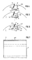
- Fig. 4: einen Querschnitt durch eine zweite Ausführungsform der erfindungsgemässen Schnellspannvorrichtung wiederum mit festgespanntem Messer,
- Fig. 5: die Querschnittzeichnung nach der Fig. 4 jedoch mit aus der Verspannung gelöstem Messer,
- Fig. 6: ebenfalls die Querschnittszeichnung gemäss der Fig. 4 jedoch mit zum Herausziehen in Radialrichtung freigegebenem Messer und
- Fig. 7: Aufriss der Werkzeug-Grundkörpers gemäss den Fig. 4 bis 6 mit radial teilweise herausgezogenem Messer.
- Wie aus Fig. 1, 2 und 4 bis 6 hervorgeht, sind in den drehbaren Werkzeug-Grundkörper 1 einer Hobelmaschine axial verlaufenden Nuten 1.1 eingearbeitet. In einer jeden Nut 1.1 ist ein Fliehkraft-Spannkeil 2 angeordnet, mit dessen Hilfe jeweils eine Einweg-Wendemesser 3 festgeklemmt werden kann. Nut 1.1 und Fliehkraft-Spannkeil 2 weisen gleichermassen eine Querschnittsform auf, die im wesentlichen ähnlich wie ein auf den Kopf gestellter Buchstabe T aussieht. Der Fliehkraft-Spannkeil 2 ist über eine Anzahl elastischer Zwischenglieder, vorzugsweise von Federn 4, gegen den Nutengrund 1.2 abgestützt, wobei die Federn 4, in der Querschnittsdarstellung der Nut 1.1 gesehen (vgl. Fig. 1,2 und 4 bis 6), in bezug auf die Mitte des Nutengrundes 1.2 unsymmetrisch angebracht sind. In einer ersten Ausführungs for der erfindungsgemässen Schnellspannvorrichtung gemäss den Fig. 1 bis 3 ist zur Gewährleistung einer genauen Führung des Fliehkraft-Spannkeils 2 bei dessen Niederdrücken in Richtung des Pfeils A zur Lösung des Einweg-Wendemessers 3 aus der Verspannung oder zum Einsetzen desselben zweckmässig jeweils zwischen Feder 4 und Nutengrund 1.2 je ein Druckkörper in der Gestalt einer Kugel 5 vorgesehen. Nach erfolgter Lösung wird das Entfernen des Einweg-Wendemessers 3 in Axialrichtung möglich (vgl. Pfeil B in Fig. 3).
- Bei einer zweiten Ausführungsförm der Erfindung nach den Fig. 4 bis 7 weist der Fliehkraft-Spannkeil 2 besonders vorteilhaft eine Formgebung auf, so dass im festgespannten Betriebszustand desselben dessen Bodenfläche eine in bezug auf den Nutengrund 1.2 schiefe Lage einnimmt. Dabei befindet sich auf Seite des Einweg-Wendemessers 3 die axiale Unterkante des Fliehkraft-Spannkeils 2 näher am Nutengrund 1.2. Wenn der Fliehkraft-Spannkeil 2 zwecks Loslösung des Einweg-Wendemessers 3 aus der Verspannung oder zum Einsetzen desselben in Richtung des Pfeils C in Fig. 5 niedergedrückt wird, kippt er um die besagte Unterkante als eine Schwenkachse in Richtung des Pfeils D in Fig. 6, bis seine Bodenfläche am Nutengrund 1.2 satt aufliegt, und gibt gleichzeitig das Einweg=Wendemesser 3 zum Herausziehen in der Radialrichtung frei (vgl. Pfeil E in Fig. 7).
- Die sich in Achsenrichtung des Werkzeug-Grundkörpers 1 erstreckenden Seitenflächen 2.1, 2.2 des aufragenden Mittelteils des Fliehkraft-Spannkeils 2 sowie die jeweils diesen benachbarten Geitenflächen 1.3, 1.4 der Nut 1.1 sind je um einen spitzen Steigungswinkel α, β gegen den Nutengrund 1.2 geneigt. Der Steigungswinkel α derjenigen einander benachbarten Seitenflächen 1.3 bzw. 2.1 von Nut 1.1 bzw. Fliehkraft-Spannkeil 2, zwischen denen jeweils das Einweg-Wendemesser 3 festgeklemmt wird, ist kleiner als der Steigungswinkel β der jeweiligen anderen Seitenflächen 1.4 bzw. 2.2 besagter Teile.
- Es ist in die letztgenannte Seitenfläche 1.4 der Nut 1.1 und die damit zusammenwirkende Seitenfläche 2.2 des Fliehkraft-Spannkeils 2 je eine in Axialrichtung verlaufende Aussparung 1.5 und 2.3 eingearbeitet. Eine hierdurch über der Aussparung 2.3 entstandene Keilnase 1.7 kann beim Niederdrücken des Fliehkraft-Spannkeils 2 in die Aussparung 1.5 der Seitenfläche 1.4 der Nut 1.1 kippen und damit das Herausnehmen des Einweg-Wendemessers 3 aus der letzteren in Radialrichtung ermöglichen (vgl. Fig. 4 bis 6).
- Zur zentrierten Aufnahme des Einweg-Wendemessers 3 ist ferner an der zugeordneten Seitenfläche 1.3 der Nut 1.1 eine Rippe 1.6 ausgebildet, die mit einer in Axialrichtung verlaufenden Wölbung 3.1 auf der Rückseite des Einweg-Wendemessers 3 zusammenwirkt (vgl. Fig. 6).
Claims (7)
Applications Claiming Priority (2)
| Application Number | Priority Date | Filing Date | Title |
|---|---|---|---|
| EP89121318 | 1989-11-17 | ||
| EP89121318 | 1989-11-17 |
Publications (2)
| Publication Number | Publication Date |
|---|---|
| EP0428996A1 true EP0428996A1 (de) | 1991-05-29 |
| EP0428996B1 EP0428996B1 (de) | 1996-07-17 |
Family
ID=8202135
Family Applications (1)
| Application Number | Title | Priority Date | Filing Date |
|---|---|---|---|
| EP90121830A Expired - Lifetime EP0428996B1 (de) | 1989-11-17 | 1990-11-14 | Fliehkraftbetätigte Schnellspannvorrichtung für Hobelmesser |
Country Status (10)
| Country | Link |
|---|---|
| US (1) | US5076334A (de) |
| EP (1) | EP0428996B1 (de) |
| JP (1) | JPH03208601A (de) |
| KR (1) | KR100216144B1 (de) |
| AT (1) | ATE140419T1 (de) |
| CA (1) | CA2030044C (de) |
| DE (1) | DE59010420D1 (de) |
| DK (1) | DK0428996T3 (de) |
| ES (1) | ES2090076T3 (de) |
| PT (1) | PT95905B (de) |
Cited By (6)
| Publication number | Priority date | Publication date | Assignee | Title |
|---|---|---|---|---|
| WO1997012734A1 (de) * | 1995-10-02 | 1997-04-10 | Robert Bosch Gmbh | Hobelmaschine, insbesondere handhobelmaschine |
| DE29711416U1 (de) * | 1997-06-30 | 1998-10-29 | Schrammel, Helmut, Dipl.-Ing. (FH), 89520 Heidenheim | Messerkopf |
| DE29711417U1 (de) * | 1997-06-30 | 1998-10-29 | Schrammel, Helmut, Dipl.-Ing. (FH), 89520 Heidenheim | Messerkopf |
| DE19813084C1 (de) * | 1998-03-25 | 1998-12-24 | Leitz Geb Gmbh & Co | Schneidwerkzeug, insbesondere Hobelmesserkopf oder Hobelmesserwelle |
| AT407132B (de) * | 1997-07-30 | 2000-12-27 | Key Knife Inc | Messerträgeranordnung |
| CH709488A1 (de) * | 2014-04-14 | 2015-10-15 | Oertli Werkzeuge Ag | Werkzeugkopf und Verfahren zum Einsetzen und Spannen einer Schneidplatte, sowie Schneidplatte. |
Families Citing this family (8)
| Publication number | Priority date | Publication date | Assignee | Title |
|---|---|---|---|---|
| DE29506458U1 (de) * | 1995-04-15 | 1995-07-06 | Gebr. Leitz GmbH & Co, 73447 Oberkochen | Messerkopf, insbesondere Hobelmesserkopf |
| JPH0924502A (ja) * | 1995-07-11 | 1997-01-28 | Shogo Tsujimoto | 電動カンナのカンナ刃及び回転ヘッド |
| US5868530A (en) * | 1995-10-12 | 1999-02-09 | Shouse; Virgil | Cutting tool |
| DE19835725B4 (de) * | 1998-08-07 | 2016-08-04 | Robert Bosch Gmbh | Hobelkopf |
| CA2686670C (en) * | 2002-01-17 | 2012-09-25 | Iggesund Tools Ab | Multi-application wood working knife and clamping assembly |
| US7517178B2 (en) * | 2005-04-01 | 2009-04-14 | Great Lakes Custom Tool Mfg., Inc. | Rotary cutter head |
| JP2007275853A (ja) * | 2006-04-12 | 2007-10-25 | Tahei Tomioka | 塗布ヘッド |
| KR102262303B1 (ko) * | 2019-10-08 | 2021-06-09 | 금호석유화학 주식회사 | 우회 흐름이 저감된 연속식 중합반응기 |
Citations (8)
| Publication number | Priority date | Publication date | Assignee | Title |
|---|---|---|---|---|
| US1405614A (en) * | 1921-04-22 | 1922-02-07 | Pb Yates Machine Co | Cutter head |
| FR610027A (fr) * | 1925-06-06 | 1926-08-28 | Const Mecaniques De Vendeuvre | Dispositif de serrage des lames de machines-outils rotatives à grande vitesse |
| FR766802A (fr) * | 1933-12-08 | 1934-07-04 | Louis Arduino & Co Soc | Perfectionnements apportés aux porte-outils à lame réglable |
| US3017912A (en) * | 1958-10-01 | 1962-01-23 | Hombak Maschinenfab Kg | Blade structure and mounting means for a cylinder type cutter |
| DE1222645B (de) * | 1961-12-19 | 1966-08-11 | Hombak Maschinenfab Kg | Messerwelle fuer Holzhobelmaschinen, insbesondere fuer Holzzerspanungsmaschinen |
| DE3437018A1 (de) * | 1984-10-09 | 1986-04-10 | Robert Bosch Gmbh, 7000 Stuttgart | Messerwalze fuer eine motorisch betriebene handhobelmaschine |
| DE8628693U1 (de) * | 1986-10-28 | 1987-08-13 | Babcock-BSH AG vormals Büttner-Schilde-Haas AG, 47829 Krefeld | Messerwelle |
| DE3642137A1 (de) * | 1986-12-10 | 1988-06-16 | Guhdo Werkzeugdienst Gmbh | Hochleistungsfraeswerkzeug fuer auswechselbare schneidplatten mit fliehkraftunterstuetztem sicherheitsspannsystem |
Family Cites Families (6)
| Publication number | Priority date | Publication date | Assignee | Title |
|---|---|---|---|---|
| DE2208687B1 (de) * | 1972-02-24 | 1973-06-14 | Hombak Maschinenfab Kg | Messerwelle für Holzbearbeitungsmaschinen |
| DE2559406A1 (de) * | 1972-03-24 | 1977-03-31 | Schaefer Karl A R | Einwegmesser fuer holzzerspanungsmaschinen |
| NL7205104A (de) * | 1972-04-14 | 1973-10-16 | ||
| DE3120249C2 (de) * | 1981-05-21 | 1983-03-17 | Hombak Maschinenfabrik Gmbh & Co Kg, 6550 Bad Kreuznach | "Messerhalterung für die Messerwelle einer Holzzerspanungsmaschine" |
| DE3239152A1 (de) * | 1982-10-22 | 1984-04-26 | Robert Bosch Gmbh, 7000 Stuttgart | Messerwalze fuer eine motorbetriebene handhobelmaschine |
| CH650431A5 (fr) * | 1983-02-09 | 1985-07-31 | Samvaz Sa | Outil de coupe a couteaux amovibles. |
-
1990
- 1990-11-14 EP EP90121830A patent/EP0428996B1/de not_active Expired - Lifetime
- 1990-11-14 US US07/613,220 patent/US5076334A/en not_active Expired - Lifetime
- 1990-11-14 DK DK90121830.5T patent/DK0428996T3/da active
- 1990-11-14 AT AT90121830T patent/ATE140419T1/de not_active IP Right Cessation
- 1990-11-14 ES ES90121830T patent/ES2090076T3/es not_active Expired - Lifetime
- 1990-11-14 DE DE59010420T patent/DE59010420D1/de not_active Expired - Fee Related
- 1990-11-15 CA CA002030044A patent/CA2030044C/en not_active Expired - Fee Related
- 1990-11-15 PT PT95905A patent/PT95905B/pt active IP Right Grant
- 1990-11-16 JP JP2312591A patent/JPH03208601A/ja active Pending
- 1990-11-16 KR KR1019900018578A patent/KR100216144B1/ko not_active Expired - Fee Related
Patent Citations (8)
| Publication number | Priority date | Publication date | Assignee | Title |
|---|---|---|---|---|
| US1405614A (en) * | 1921-04-22 | 1922-02-07 | Pb Yates Machine Co | Cutter head |
| FR610027A (fr) * | 1925-06-06 | 1926-08-28 | Const Mecaniques De Vendeuvre | Dispositif de serrage des lames de machines-outils rotatives à grande vitesse |
| FR766802A (fr) * | 1933-12-08 | 1934-07-04 | Louis Arduino & Co Soc | Perfectionnements apportés aux porte-outils à lame réglable |
| US3017912A (en) * | 1958-10-01 | 1962-01-23 | Hombak Maschinenfab Kg | Blade structure and mounting means for a cylinder type cutter |
| DE1222645B (de) * | 1961-12-19 | 1966-08-11 | Hombak Maschinenfab Kg | Messerwelle fuer Holzhobelmaschinen, insbesondere fuer Holzzerspanungsmaschinen |
| DE3437018A1 (de) * | 1984-10-09 | 1986-04-10 | Robert Bosch Gmbh, 7000 Stuttgart | Messerwalze fuer eine motorisch betriebene handhobelmaschine |
| DE8628693U1 (de) * | 1986-10-28 | 1987-08-13 | Babcock-BSH AG vormals Büttner-Schilde-Haas AG, 47829 Krefeld | Messerwelle |
| DE3642137A1 (de) * | 1986-12-10 | 1988-06-16 | Guhdo Werkzeugdienst Gmbh | Hochleistungsfraeswerkzeug fuer auswechselbare schneidplatten mit fliehkraftunterstuetztem sicherheitsspannsystem |
Cited By (10)
| Publication number | Priority date | Publication date | Assignee | Title |
|---|---|---|---|---|
| WO1997012734A1 (de) * | 1995-10-02 | 1997-04-10 | Robert Bosch Gmbh | Hobelmaschine, insbesondere handhobelmaschine |
| DE29711416U1 (de) * | 1997-06-30 | 1998-10-29 | Schrammel, Helmut, Dipl.-Ing. (FH), 89520 Heidenheim | Messerkopf |
| DE29711417U1 (de) * | 1997-06-30 | 1998-10-29 | Schrammel, Helmut, Dipl.-Ing. (FH), 89520 Heidenheim | Messerkopf |
| AT407132B (de) * | 1997-07-30 | 2000-12-27 | Key Knife Inc | Messerträgeranordnung |
| DE19813084C1 (de) * | 1998-03-25 | 1998-12-24 | Leitz Geb Gmbh & Co | Schneidwerkzeug, insbesondere Hobelmesserkopf oder Hobelmesserwelle |
| WO1999048655A3 (de) * | 1998-03-25 | 1999-10-28 | Leitz Geb Gmbh & Co | Schneidwerkzeug, insbesondere hobelmesserkopf oder hobelmesserwelle |
| US6279444B1 (en) | 1998-03-25 | 2001-08-28 | Leitz Gmbh & Co. Kg | Cutting tool, especially plane blade head or plane blade shaft |
| CH709488A1 (de) * | 2014-04-14 | 2015-10-15 | Oertli Werkzeuge Ag | Werkzeugkopf und Verfahren zum Einsetzen und Spannen einer Schneidplatte, sowie Schneidplatte. |
| WO2015157871A3 (de) * | 2014-04-14 | 2015-12-03 | Oertli Werkzeuge Ag | Werkzeugkopf und verfahren zum einsetzen und spannen einer schneidplatte, sowie schneidplatte |
| US11298851B2 (en) | 2014-04-14 | 2022-04-12 | Oertli Werkzeuge Ag | Tool head and method for inserting and clamping a cutting insert, and cutting insert |
Also Published As
| Publication number | Publication date |
|---|---|
| KR910009373A (ko) | 1991-06-28 |
| CA2030044C (en) | 2002-04-16 |
| DE59010420D1 (de) | 1996-08-22 |
| ES2090076T3 (es) | 1996-10-16 |
| CA2030044A1 (en) | 1991-05-18 |
| ATE140419T1 (de) | 1996-08-15 |
| PT95905B (pt) | 1998-07-31 |
| PT95905A (pt) | 1992-08-31 |
| DK0428996T3 (da) | 1996-08-12 |
| US5076334A (en) | 1991-12-31 |
| JPH03208601A (ja) | 1991-09-11 |
| EP0428996B1 (de) | 1996-07-17 |
| KR100216144B1 (ko) | 1999-08-16 |
Similar Documents
| Publication | Publication Date | Title |
|---|---|---|
| DE69802998T2 (de) | Ein- und Abstechwerkzeug | |
| EP0428996A1 (de) | Fliehkraftbetätigte Schnellspannvorrichtung für Hobelmesser | |
| DE3211766A1 (de) | Schlitzschneider | |
| DE3044790A1 (de) | Scheibenfraeser | |
| DE3815295A1 (de) | Messer-messerhalter-anordnung | |
| EP0259847A1 (de) | Werkzeug zur spanabhebenden Metallbearbeitung wie Anfasen, Stechen, Plandrehen und Fräsen | |
| CH650187A5 (de) | Verfahren zur herstellung einer schleif- oder polierscheibe und ein nach diesem hergestelltes werkzeug. | |
| WO1996033056A1 (de) | Messerkopf, insbesondere hobelmesserkopf | |
| DE4445909A1 (de) | Sägeblatt | |
| DE69221887T2 (de) | Nutfräse mit schneideeinsätzen gespannt durch exzenter oder nocken | |
| DE2428426B2 (de) | Vorrichtung zum Stirnschleifen von versenkt arbeitenden Schneidwerkzeugen | |
| DE2714468C2 (de) | Metallstreifen mit voneinander beabstandeten Klingen zur Herstellung chirurgischer Klingen und Verfahren zur Aufbereitung | |
| DE1652773B2 (de) | Saegeblatt | |
| EP1341652B1 (de) | Trenneinrichtung für unterwassergranulatoren | |
| DE3420653A1 (de) | Schneid- oder abstechwerkzeug | |
| EP0145049B1 (de) | Abisoliervorrichtung, insbesondere für Leiter mit zäher Isolationsschicht | |
| DE3043146A1 (de) | Messerkopf | |
| DE2429145A1 (de) | Vorrichtung zum abscheiden von material von fahrzeugreifen fuer die runderneuerung | |
| CH682470A5 (de) | Fräswerkzeug. | |
| EP0717921B1 (de) | Kreiselmäher und Messerwechsel-Werkzeug | |
| DE69933354T2 (de) | Blockiervorrichtung für Schneideinsätze oder Messer an einem Fräskopf | |
| DE2608056C3 (de) | Holzzerspanungsmaschine | |
| DE1222763C2 (de) | Spanabhebendes werkzeug | |
| DE761450C (de) | Sicherheitsrasierapparat mit einem aus zwei Teilen bestehenden Kamm, wobei die Teile mit zwei biegsamen oder starren Flanschen eines hierzu angepassten Griffes verbundensind | |
| DE3638068C1 (de) | Fraesvorrichtung zum Bearbeiten,insbesondere Besaeumen,der Kanten von Blechbaendern,Blechplatten oder dgl. |
Legal Events
| Date | Code | Title | Description |
|---|---|---|---|
| PUAI | Public reference made under article 153(3) epc to a published international application that has entered the european phase |
Free format text: ORIGINAL CODE: 0009012 |
|
| AK | Designated contracting states |
Kind code of ref document: A1 Designated state(s): AT BE CH DE DK ES FR GB GR IT LI LU NL SE |
|
| 17P | Request for examination filed |
Effective date: 19911126 |
|
| 17Q | First examination report despatched |
Effective date: 19920708 |
|
| RAP1 | Party data changed (applicant data changed or rights of an application transferred) |
Owner name: PETER FREY CONSULTING |
|
| ITF | It: translation for a ep patent filed | ||
| GRAH | Despatch of communication of intention to grant a patent |
Free format text: ORIGINAL CODE: EPIDOS IGRA |
|
| GRAA | (expected) grant |
Free format text: ORIGINAL CODE: 0009210 |
|
| AK | Designated contracting states |
Kind code of ref document: B1 Designated state(s): AT BE CH DE DK ES FR GB GR IT LI LU NL SE |
|
| PG25 | Lapsed in a contracting state [announced via postgrant information from national office to epo] |
Ref country code: GR Free format text: LAPSE BECAUSE OF FAILURE TO SUBMIT A TRANSLATION OF THE DESCRIPTION OR TO PAY THE FEE WITHIN THE PRESCRIBED TIME-LIMIT Effective date: 19960717 |
|
| REF | Corresponds to: |
Ref document number: 140419 Country of ref document: AT Date of ref document: 19960815 Kind code of ref document: T |
|
| REG | Reference to a national code |
Ref country code: CH Ref legal event code: NV Representative=s name: BUECHEL, VON REVY & PARTNER |
|
| REG | Reference to a national code |
Ref country code: DK Ref legal event code: T3 |
|
| ET | Fr: translation filed | ||
| REF | Corresponds to: |
Ref document number: 59010420 Country of ref document: DE Date of ref document: 19960822 |
|
| GBT | Gb: translation of ep patent filed (gb section 77(6)(a)/1977) |
Effective date: 19960820 |
|
| REG | Reference to a national code |
Ref country code: ES Ref legal event code: FG2A Ref document number: 2090076 Country of ref document: ES Kind code of ref document: T3 |
|
| REG | Reference to a national code |
Ref country code: ES Ref legal event code: FG2A Ref document number: 2090076 Country of ref document: ES Kind code of ref document: T3 |
|
| PG25 | Lapsed in a contracting state [announced via postgrant information from national office to epo] |
Ref country code: LU Free format text: LAPSE BECAUSE OF NON-PAYMENT OF DUE FEES Effective date: 19961130 |
|
| PLBE | No opposition filed within time limit |
Free format text: ORIGINAL CODE: 0009261 |
|
| STAA | Information on the status of an ep patent application or granted ep patent |
Free format text: STATUS: NO OPPOSITION FILED WITHIN TIME LIMIT |
|
| 26N | No opposition filed | ||
| PGFP | Annual fee paid to national office [announced via postgrant information from national office to epo] |
Ref country code: DK Payment date: 20010927 Year of fee payment: 12 |
|
| PGFP | Annual fee paid to national office [announced via postgrant information from national office to epo] |
Ref country code: BE Payment date: 20011121 Year of fee payment: 12 |
|
| PGFP | Annual fee paid to national office [announced via postgrant information from national office to epo] |
Ref country code: NL Payment date: 20011130 Year of fee payment: 12 |
|
| REG | Reference to a national code |
Ref country code: GB Ref legal event code: IF02 |
|
| PG25 | Lapsed in a contracting state [announced via postgrant information from national office to epo] |
Ref country code: BE Free format text: LAPSE BECAUSE OF NON-PAYMENT OF DUE FEES Effective date: 20021130 |
|
| PG25 | Lapsed in a contracting state [announced via postgrant information from national office to epo] |
Ref country code: DK Free format text: LAPSE BECAUSE OF NON-PAYMENT OF DUE FEES Effective date: 20021231 |
|
| BERE | Be: lapsed |
Owner name: PETER *FREY CONSULTING Effective date: 20021130 |
|
| PG25 | Lapsed in a contracting state [announced via postgrant information from national office to epo] |
Ref country code: NL Free format text: LAPSE BECAUSE OF NON-PAYMENT OF DUE FEES Effective date: 20030601 |
|
| REG | Reference to a national code |
Ref country code: DK Ref legal event code: EBP |
|
| NLV4 | Nl: lapsed or anulled due to non-payment of the annual fee |
Effective date: 20030601 |
|
| PGFP | Annual fee paid to national office [announced via postgrant information from national office to epo] |
Ref country code: SE Payment date: 20031031 Year of fee payment: 14 |
|
| PGFP | Annual fee paid to national office [announced via postgrant information from national office to epo] |
Ref country code: GB Payment date: 20031104 Year of fee payment: 14 |
|
| PGFP | Annual fee paid to national office [announced via postgrant information from national office to epo] |
Ref country code: AT Payment date: 20031112 Year of fee payment: 14 |
|
| PGFP | Annual fee paid to national office [announced via postgrant information from national office to epo] |
Ref country code: FR Payment date: 20031128 Year of fee payment: 14 |
|
| PGFP | Annual fee paid to national office [announced via postgrant information from national office to epo] |
Ref country code: CH Payment date: 20031218 Year of fee payment: 14 |
|
| PGFP | Annual fee paid to national office [announced via postgrant information from national office to epo] |
Ref country code: ES Payment date: 20031230 Year of fee payment: 14 |
|
| PGFP | Annual fee paid to national office [announced via postgrant information from national office to epo] |
Ref country code: DE Payment date: 20040127 Year of fee payment: 14 |
|
| PG25 | Lapsed in a contracting state [announced via postgrant information from national office to epo] |
Ref country code: GB Free format text: LAPSE BECAUSE OF NON-PAYMENT OF DUE FEES Effective date: 20041114 Ref country code: AT Free format text: LAPSE BECAUSE OF NON-PAYMENT OF DUE FEES Effective date: 20041114 |
|
| PG25 | Lapsed in a contracting state [announced via postgrant information from national office to epo] |
Ref country code: SE Free format text: LAPSE BECAUSE OF NON-PAYMENT OF DUE FEES Effective date: 20041115 Ref country code: ES Free format text: LAPSE BECAUSE OF NON-PAYMENT OF DUE FEES Effective date: 20041115 |
|
| PG25 | Lapsed in a contracting state [announced via postgrant information from national office to epo] |
Ref country code: LI Free format text: LAPSE BECAUSE OF NON-PAYMENT OF DUE FEES Effective date: 20041130 Ref country code: CH Free format text: LAPSE BECAUSE OF NON-PAYMENT OF DUE FEES Effective date: 20041130 |
|
| PG25 | Lapsed in a contracting state [announced via postgrant information from national office to epo] |
Ref country code: DE Free format text: LAPSE BECAUSE OF NON-PAYMENT OF DUE FEES Effective date: 20050601 |
|
| EUG | Se: european patent has lapsed | ||
| GBPC | Gb: european patent ceased through non-payment of renewal fee |
Effective date: 20041114 |
|
| REG | Reference to a national code |
Ref country code: CH Ref legal event code: PL |
|
| PG25 | Lapsed in a contracting state [announced via postgrant information from national office to epo] |
Ref country code: FR Free format text: LAPSE BECAUSE OF NON-PAYMENT OF DUE FEES Effective date: 20050729 |
|
| REG | Reference to a national code |
Ref country code: FR Ref legal event code: ST |
|
| PG25 | Lapsed in a contracting state [announced via postgrant information from national office to epo] |
Ref country code: IT Free format text: LAPSE BECAUSE OF NON-PAYMENT OF DUE FEES Effective date: 20051114 |
|
| REG | Reference to a national code |
Ref country code: ES Ref legal event code: FD2A Effective date: 20041115 |