EP0429079A2 - Plattenvorrichtung mit Reinigungsvorrichtung und Reinigungsverfahren - Google Patents
Plattenvorrichtung mit Reinigungsvorrichtung und Reinigungsverfahren Download PDFInfo
- Publication number
- EP0429079A2 EP0429079A2 EP90122316A EP90122316A EP0429079A2 EP 0429079 A2 EP0429079 A2 EP 0429079A2 EP 90122316 A EP90122316 A EP 90122316A EP 90122316 A EP90122316 A EP 90122316A EP 0429079 A2 EP0429079 A2 EP 0429079A2
- Authority
- EP
- European Patent Office
- Prior art keywords
- disk
- cleaning
- slider
- seeking
- motor
- Prior art date
- Legal status (The legal status is an assumption and is not a legal conclusion. Google has not performed a legal analysis and makes no representation as to the accuracy of the status listed.)
- Granted
Links
Images




Classifications
-
- G—PHYSICS
- G11—INFORMATION STORAGE
- G11B—INFORMATION STORAGE BASED ON RELATIVE MOVEMENT BETWEEN RECORD CARRIER AND TRANSDUCER
- G11B5/00—Recording by magnetisation or demagnetisation of a record carrier; Reproducing by magnetic means; Record carriers therefor
- G11B5/48—Disposition or mounting of heads or head supports relative to record carriers ; arrangements of heads, e.g. for scanning the record carrier to increase the relative speed
- G11B5/58—Disposition or mounting of heads or head supports relative to record carriers ; arrangements of heads, e.g. for scanning the record carrier to increase the relative speed with provision for moving the head for the purpose of maintaining alignment of the head relative to the record carrier during transducing operation, e.g. to compensate for surface irregularities of the latter or for track following
- G11B5/60—Fluid-dynamic spacing of heads from record-carriers
- G11B5/6005—Specially adapted for spacing from a rotating disc using a fluid cushion
-
- G—PHYSICS
- G11—INFORMATION STORAGE
- G11B—INFORMATION STORAGE BASED ON RELATIVE MOVEMENT BETWEEN RECORD CARRIER AND TRANSDUCER
- G11B23/00—Record carriers not specific to the method of recording or reproducing; Accessories, e.g. containers, specially adapted for co-operation with the recording or reproducing apparatus ; Intermediate mediums; Apparatus or processes specially adapted for their manufacture
- G11B23/50—Reconditioning of record carriers; Cleaning of record carriers ; Carrying-off electrostatic charges
- G11B23/505—Reconditioning of record carriers; Cleaning of record carriers ; Carrying-off electrostatic charges of disk carriers
-
- G—PHYSICS
- G11—INFORMATION STORAGE
- G11B—INFORMATION STORAGE BASED ON RELATIVE MOVEMENT BETWEEN RECORD CARRIER AND TRANSDUCER
- G11B5/00—Recording by magnetisation or demagnetisation of a record carrier; Reproducing by magnetic means; Record carriers therefor
- G11B5/41—Cleaning of heads
Definitions
- the present invention relates to a disk device as one of external memory devices of a computer, and more specifically to disk cleaning.
- FIGs. 8 through 11 there are illustrated operations of a magnetic disk and a magnetic head in a magnetic disk device, respectively.
- a magnetic disk designated at 1 is a magnetic disk
- 2 is a slider for holding a transducer that is to record/regenerate information on/from the disk 1
- 3 is a support spring for forcing the slider 2 to follow up the disk 1
- 4 is a tapered portion provided on the slider 2
- 5 is an arrow indicating the direction of rotation of the disk 1 at recording and regeneration on the disk
- 6 is an arrow indicating the direction of seeking by the slider 2
- 7 is dust
- 8 is a non-recording region on the disk 1.
- the slider 2 is pushed against the disk 1 by the support spring 3 at a static state, and is allowed to make static contact with the disk 1.
- the slider 2 is allowed to float and stop generally in a non-recorded region 8 of the disk 1 as indicated by a dotted line in FIG. 9. As the disk 1 goes into steady rotation, the slider 2 moves to a position indicated by a solid line 2 in the figure, and selects a track arranged coaxially on the disk 1 while seeking those tracks in the direction indicated by the arrow 6, to record/regenerate information on/from the track.
- the slider 2 which is pushed up and lifted by wind pressure excerted on the tapered portion 4 as shown in FIG. 10, is lifted to a higher position on the leading edge side where the tapered portion 4 has been provided, while being lifted to a lowest position, a height h2, on the trailing edge side.
- any dust such as dirt (hereinafter referred to dust ) existent around the disk 1 is entrained by the air flow with the rotation of the disk 1 to strike the tapered portion 4 of the slider 2 together with the air flow, and allowed to adhere partly to the tapered portion 4. This causes such dust to be accumulated on the tapered portion 4 located on the back side of the slider 2 for a long period of time, as illustrated in FIG. 11.
- any dust is accumulated on the tapered portion with the elapse of time as described above.
- the slider is however difficult to be cleaned.
- a closed magnetic device capable of dealing with a recent trend of making the device high density, it is impossible to clean the interior of the device without decomposing the device, and accumulated dust interrupts the operation of the tapered portion to cause the unstable lifted attitude of the slider and hence head crushing.
- a magnetic disk device disclosed in the device of Japanese Utility Model Laid-Open No. 62-57999.
- any dust adhering to a disk surface is scattered by a slider by rotating the disk at a low rotational speed in the same direction as the direction of rotation of the disk during recording and regeneration, and bringing the slider near to the disk surface to repeatedly seek the disk several times.
- a disk device with a cleaning deive and a cleaning method comprises cleaning motor control means for rotating a disk oppositely to a direction of the same at recording and regeneration and seeking means for forcing said slider to seek the disk over a whole recording area on the same when said disk is being rotated oppositely for allowing any dust to be deposited on the slider, said cleaning motor control means stops (CSS. Contact-Start-Stop) the driving of a motor, after the slider is sought, to force the dust deposited on said slider to fall on a disk surface.
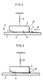
- FIGs. 1 through 5 there are illustrated an embodiment of a disk device including a cleaning device, and a cleaning method, respectively.
- the same symbols as those illustrated in FIGs. 8 through 11 indicate the same or corresponding portions.
- FIG. 1 is the block diagram of the embodiment of the disk device having the cleaning device according to the present invention
- a plurality of magnetic disks 1 are attached to a spindle 10 which is forwardly or backwardly rotated or stopped by a motor 11.
- the motor 11 is driven and stopped by a driver 13 connected to a power supply, and the driver 13 is controlled by motor control means 14.
- An arm 15, which supports a spring 3, is driven by an actuator 16.
- a slider 2 is shifted radially (in the direction of an arrow M) of the magnetic disk, and sought.
- the actuator 16 is controlled by positioning means 18 through a driver 17 connected to the power supply.
- Designated at 26 is writing means for writing any information on a magnetic head 21 by supplying power to a magnetic head 21 through a driver 20, and 27 is reading means for reading through the driver 20 any information read by the magnetic head 21. Additionally, designated at 23 is seeking means for seeking the slider 2 by driving the same according to an instruction from dust removal instructing means 24, 25 is cleaning motor control means for reversely rotating the motor 11 and repeatedly driving and stopping the same by driving the same according to an instruction from the dust removal instructing means 24, 28 is control means, 29 is a ROM, and 30 is a RAM.
- an arrow designated at 9 indicates the direction of rotation of the disk 1 at self-cleaning, that is an opposite direction to the direction of rotation 5 of the same at recording and regeneration
- a symbol h1 designates a floating height of the slider 2 when the disk 1 is rotated at a low rotational speed in the direction of the arrow 9.
- the height h1 is sufficiently smaller than a height h z shown in FIG. 10.
- the motor control means 14 is driven by the control means 28 to drive the motor 11 forwardly and hence rotate the disk 11 forwardly, say in the direction of the arrow 5.
- the slider 2 is driven to float by h z .
- the positioning means 18 is driven to position the slider 2 from the non-recording region 8 to a predetermined track in a recording region 8A for write/read operation of information by the writing means 26 or the reading means 27.
- a self-cleaning of the magnetic disk is performed prior to the start of the aforementioned write/read operation.
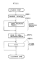
- the cleaning motor control means 25 is actuated by the dust removal instructing means 24 to rotate the disk 1 at a low rotational speed in the opposite direction to that indicated by the arrow 9, i.e., in the opposite direction to the ordinary read/write direction (Step 1).
- such a rotational speed of the disk 1 in the reverse direction indicated by the arrow 9 may be about 500 ⁇ 1,000 rpm although an ordinary one is 3,600 rpm.
- the reason to rotate the disk 1 at the low rotational speed is as follows: the floating height of the slider 2 is substantially determined by a relative speed between the disk 1 and the slider 2 if the shape of the slider remains unchanged, and the floating height of the slider 2 is higher as the relative speed is higher.
- any floating dust which is very small in size, simply passes through between the disk 1 and the slider 2 when the floating height is greater, and hence does not adhere to the slider 2 so much. Accordingly, the disk 1 is rotated at the low rotational speed to permit the slider 2 to float at a low height for allowing any dust to be liable to adhere to the slider 2.
- the disk 1 is rotated in the recording region 8A to permit any coming dust to positively adhere to the trailing edge side of the slider 2.
- the seeking means 23 is actuated to repeatedly seek the track surface of the disk 1 in the recording region 8A in the direction of the arrow 6 for cleaning of the recording region 8A on the disk 1 (Step 2).
- the seeking means 23 moves the slider 2 to the non-recording region 8 which is not used during the recording and regeneration (Step 3)
- the cleaning motor control means 25 repeatedly drives and stops the motor in the non-recording region 8 to repeatedly perform the CSS (Contact-Start-Stop) of the slider 2 to the magnetic disk 1.
- the disk 1 is rotated in the ordinary direction of rotation.
- Step 4 any dust adhering to the trailing edge is forced to positively fall on the disk surface for cleaning the slider 2, as illustrated in FIG. 3.
- the write/read operation of the information is interrupted during the actuation of the dust removal instructing means 24.
- the foregoing CSS means that the slider 2 makes contact with the disk surface during the stop of the disk and it floats as the speed of rotation of the disk increases.
- the cleaning of the slider 2 has been described as being done in the same direction as the ordinary direction of the rotation of the disk 1, this originates from a fact that exfoliating force to any dust is produced in the opposite direction to the adherence of the dust to ease the falling of the dust.
- the disk 1 may be reversed in its rotation at each CSS.
- the falling of any dust may be secured by making thick a lubricating layer in the non-recording region 8 or by properly varying the surface roughness of that region.
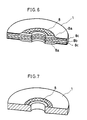
- the slider 2 is liable to attract any dust as the lubricating layer 8a is made thicker. Accordingly, the slider 2 can easily attract any dust in the non-recording region 8 with such construction as illustrated in FIG. 6. Hereby, any dust on the slider 2 is liable to fall with the repeated CSS.
- numeral 8b is a substrate and 8c is a magnetic layer, in FIG. 6.
- frictional force is made greater to ease the falling of the dust on the slider 2 provided that the surface of the non-recording region 8 is roughened.
- the roughened surface was illustrated as extending over the whole non-recording region 8, the surface may be existent on a track partially in the non-recording region 8, which track may be used as a track only for cleaning the slider. Further, a combination of FIG. 6 and 7 may be used.
- control means 28 steadily rotates the disk 1 in the direction indicated by the arrow 5 for recording and regeneration of information on the disk 1.
- the timing to perform the self-cleaning may be set such that it is performed each time the write/read operation is completed or every predetermined time, not limited to the time that the device is actuated for the write/read operation.
- the self-cleaning may be started when the write/read operation is performed a preset number of times which is counted by a write/read starting counter provided anew.
- the repeated actuation and interruption of the motor by the cleaning motor control means 25 after the completion of the cleaning may be performed at the recording region without shifting the slider 2 to the non-recording region 8 and may scatter any falling dust in the recording region 8A to the outside by making use of centrifugal force.
- the present invention has an advantage that the adhesion of the dust to the tapered portion can be prevented, since the cleaning is performed by rotating the disk in the direction opposite to the rotational direction at recording and regeneration, so that a highly reliable disk device having a cleaning device and a cleaning method can be provided.
Landscapes
- Supporting Of Heads In Record-Carrier Devices (AREA)
- Manufacturing Of Magnetic Record Carriers (AREA)
- Rotational Drive Of Disk (AREA)
Applications Claiming Priority (2)
| Application Number | Priority Date | Filing Date | Title |
|---|---|---|---|
| JP1304321A JPH03165386A (ja) | 1989-11-22 | 1989-11-22 | 磁気ディスク装置 |
| JP304321/89 | 1989-11-22 |
Publications (3)
| Publication Number | Publication Date |
|---|---|
| EP0429079A2 true EP0429079A2 (de) | 1991-05-29 |
| EP0429079A3 EP0429079A3 (en) | 1992-01-22 |
| EP0429079B1 EP0429079B1 (de) | 1995-08-16 |
Family
ID=17931620
Family Applications (1)
| Application Number | Title | Priority Date | Filing Date |
|---|---|---|---|
| EP90122316A Expired - Lifetime EP0429079B1 (de) | 1989-11-22 | 1990-11-22 | Plattenvorrichtung mit Reinigungsvorrichtung und Reinigungsverfahren |
Country Status (5)
| Country | Link |
|---|---|
| US (1) | US5424884A (de) |
| EP (1) | EP0429079B1 (de) |
| JP (1) | JPH03165386A (de) |
| CA (1) | CA2030341C (de) |
| DE (1) | DE69021690T2 (de) |
Cited By (3)
| Publication number | Priority date | Publication date | Assignee | Title |
|---|---|---|---|---|
| EP0470857A1 (de) * | 1990-08-10 | 1992-02-12 | Mitsubishi Denki Kabushiki Kaisha | Vorrichtung zur Reinigung von Platten und eine solche Vorrichtung enthaltendes Plattenabspielgerät |
| EP0562994A3 (en) * | 1992-03-25 | 1994-07-27 | Ibm | Method and apparatus for cleaning disks |
| EP0802526A3 (de) * | 1996-04-19 | 1998-05-20 | International Business Machines Corporation | Speichervorrichtung |
Families Citing this family (14)
| Publication number | Priority date | Publication date | Assignee | Title |
|---|---|---|---|---|
| JP2810824B2 (ja) * | 1992-07-03 | 1998-10-15 | 富士通株式会社 | 光ディスク装置 |
| AU708512B2 (en) * | 1995-03-14 | 1999-08-05 | Joseph Frederick Fritsch | A cleaning device and cleaning method |
| JPH09251728A (ja) * | 1996-03-15 | 1997-09-22 | Toshiba Corp | ディスク記録再生装置及びそのリードエラー処理方法 |
| US5850321A (en) | 1996-09-18 | 1998-12-15 | Maxtor Corporation | Self-cleaning proximity recording interface |
| US6687077B1 (en) * | 1996-09-18 | 2004-02-03 | Maxtor Corporation | Method for controlling a spin motor in a disk drive during cleaning and read/write operations |
| JP2933042B2 (ja) | 1996-12-20 | 1999-08-09 | 日本電気株式会社 | 磁気ディスク装置 |
| US5751517A (en) * | 1997-04-11 | 1998-05-12 | Western Digital Corporation | Air bearing slider having debris removing channels |
| US6088199A (en) * | 1997-05-15 | 2000-07-11 | Samsung Electronics Co., Ltd. | Magnetic disk for self-cleaning a disk drive recording head |
| KR100271617B1 (ko) * | 1997-06-03 | 2000-11-15 | 윤종용 | 드롭다운(DropDown)현상을최소화하기위한예비탐색방법 |
| JP3861387B2 (ja) * | 1997-07-02 | 2006-12-20 | 富士通株式会社 | ヘッドスライダとディスク装置 |
| US6307832B1 (en) * | 1999-05-04 | 2001-10-23 | Terastor Corporation | Optical storage system with head cleaning mechanism based on a position-controllable optical interfacing surface in an optical head |
| US7088532B1 (en) | 2001-04-19 | 2006-08-08 | Maxtor Corporation | Head-disk interface preconditioning using write current before servo track write |
| US7561367B2 (en) * | 2007-09-14 | 2009-07-14 | Seagate Technology Llc | Bi-directional debris sweeping profile |
| US20090216675A1 (en) * | 2008-02-21 | 2009-08-27 | The Coca-Cola Company | Commission Centric Network Operation Systems and Methods |
Family Cites Families (11)
| Publication number | Priority date | Publication date | Assignee | Title |
|---|---|---|---|---|
| US3609721A (en) * | 1969-03-03 | 1971-09-28 | Singer Co | Method of clearing dust from a magnetic record disc or the like |
| JPS56169226A (en) * | 1980-05-30 | 1981-12-25 | Fujitsu Ltd | Magnetic disk device |
| JPS57200971A (en) * | 1981-06-01 | 1982-12-09 | Hitachi Ltd | Magnetic disk storage device |
| US4384311A (en) * | 1981-10-13 | 1983-05-17 | Dma Systems Corporation | Method for cleaning the disc surface and the head support structure in a magnetic disc drive |
| US4490766A (en) * | 1982-03-22 | 1984-12-25 | International Business Machines Corporation | Magnetic recording disk cleaning using controlled actuator motion |
| US4594617A (en) * | 1982-08-11 | 1986-06-10 | Canon Kabushiki Kaisha | Method and apparatus for cleaning a recording and/or reproducing head |
| JPS6050614A (ja) * | 1983-08-27 | 1985-03-20 | Canon Inc | ヘツド清掃方法及びその装置 |
| JPS60136950A (ja) * | 1983-12-26 | 1985-07-20 | Nec Corp | 磁気デイスク装置の起動方式 |
| JPS61182685A (ja) * | 1985-02-08 | 1986-08-15 | Sanyo Electric Co Ltd | デイスクプレイヤ− |
| US4693015A (en) * | 1985-08-26 | 1987-09-15 | Hercules Incorporated | Direct fired cylinder dryer |
| JPH01189017A (ja) * | 1988-01-22 | 1989-07-28 | Tokyo Electric Co Ltd | フロツピーデイスクドライブ装置 |
-
1989
- 1989-11-22 JP JP1304321A patent/JPH03165386A/ja active Pending
-
1990
- 1990-11-20 CA CA002030341A patent/CA2030341C/en not_active Expired - Fee Related
- 1990-11-22 EP EP90122316A patent/EP0429079B1/de not_active Expired - Lifetime
- 1990-11-22 DE DE69021690T patent/DE69021690T2/de not_active Expired - Fee Related
-
1993
- 1993-09-30 US US08/129,801 patent/US5424884A/en not_active Expired - Fee Related
Cited By (4)
| Publication number | Priority date | Publication date | Assignee | Title |
|---|---|---|---|---|
| EP0470857A1 (de) * | 1990-08-10 | 1992-02-12 | Mitsubishi Denki Kabushiki Kaisha | Vorrichtung zur Reinigung von Platten und eine solche Vorrichtung enthaltendes Plattenabspielgerät |
| EP0562994A3 (en) * | 1992-03-25 | 1994-07-27 | Ibm | Method and apparatus for cleaning disks |
| US5612830A (en) * | 1992-03-25 | 1997-03-18 | International Business Machines Corporation | Method and apparatus for cleaning disks upon reaching a disk drive start-stop cycle threshold |
| EP0802526A3 (de) * | 1996-04-19 | 1998-05-20 | International Business Machines Corporation | Speichervorrichtung |
Also Published As
| Publication number | Publication date |
|---|---|
| CA2030341A1 (en) | 1991-05-23 |
| EP0429079B1 (de) | 1995-08-16 |
| CA2030341C (en) | 1996-12-03 |
| JPH03165386A (ja) | 1991-07-17 |
| US5424884A (en) | 1995-06-13 |
| DE69021690T2 (de) | 1996-02-15 |
| EP0429079A3 (en) | 1992-01-22 |
| DE69021690D1 (de) | 1995-09-21 |
Similar Documents
| Publication | Publication Date | Title |
|---|---|---|
| EP0429079B1 (de) | Plattenvorrichtung mit Reinigungsvorrichtung und Reinigungsverfahren | |
| US5612830A (en) | Method and apparatus for cleaning disks upon reaching a disk drive start-stop cycle threshold | |
| US4384311A (en) | Method for cleaning the disc surface and the head support structure in a magnetic disc drive | |
| JPH0355909B2 (de) | ||
| CN1115667C (zh) | 用于磁盘驱动器的浮动块清洁方法和装置 | |
| KR0175255B1 (ko) | 하드디스크 드라이브의 자기기록용 헤드 | |
| US6493168B1 (en) | Method for cleaning a slider in a disk drive | |
| US5798884A (en) | Multiple zone data storage system and method | |
| US4490766A (en) | Magnetic recording disk cleaning using controlled actuator motion | |
| US5793553A (en) | Method and assembly for increasing storage device reliability | |
| EP0604967B1 (de) | Magnetplattenantrieb | |
| JPH05166318A (ja) | ディスク装置 | |
| JP2000510635A (ja) | 低速度のもとでヘッドをローディングして行うヘッドクリーニング | |
| WO1997019449A9 (en) | Head cleaning by loading heads at low speed | |
| US6687077B1 (en) | Method for controlling a spin motor in a disk drive during cleaning and read/write operations | |
| US5870264A (en) | Method and arrangement for significantly increasing the lifetime of magnetic disk storage devices | |
| JPH01149211A (ja) | 磁気デイスク装置 | |
| JPS6226620A (ja) | 磁気デイスク装置 | |
| JPH11162139A (ja) | 磁気ヘッド装置 | |
| JPS6273424A (ja) | 磁気記録円板のバ−ニツシユ方法 | |
| JPH01165080A (ja) | 回転磁気シート装置 | |
| JPH01184681A (ja) | 磁気ディスク装置 | |
| JP2006228408A (ja) | ヘッドクリーニング装置 | |
| JPH02128381A (ja) | 磁気ディスク装置 | |
| JPH11126447A (ja) | 磁気ディスク装置 |
Legal Events
| Date | Code | Title | Description |
|---|---|---|---|
| PUAI | Public reference made under article 153(3) epc to a published international application that has entered the european phase |
Free format text: ORIGINAL CODE: 0009012 |
|
| 17P | Request for examination filed |
Effective date: 19901228 |
|
| AK | Designated contracting states |
Kind code of ref document: A2 Designated state(s): DE FR GB |
|
| PUAL | Search report despatched |
Free format text: ORIGINAL CODE: 0009013 |
|
| AK | Designated contracting states |
Kind code of ref document: A3 Designated state(s): DE FR GB |
|
| 17Q | First examination report despatched |
Effective date: 19940428 |
|
| GRAA | (expected) grant |
Free format text: ORIGINAL CODE: 0009210 |
|
| AK | Designated contracting states |
Kind code of ref document: B1 Designated state(s): DE FR GB |
|
| REF | Corresponds to: |
Ref document number: 69021690 Country of ref document: DE Date of ref document: 19950921 |
|
| ET | Fr: translation filed | ||
| PLBE | No opposition filed within time limit |
Free format text: ORIGINAL CODE: 0009261 |
|
| STAA | Information on the status of an ep patent application or granted ep patent |
Free format text: STATUS: NO OPPOSITION FILED WITHIN TIME LIMIT |
|
| 26N | No opposition filed | ||
| REG | Reference to a national code |
Ref country code: GB Ref legal event code: 746 Effective date: 20000126 |
|
| REG | Reference to a national code |
Ref country code: FR Ref legal event code: D6 |
|
| PGFP | Annual fee paid to national office [announced via postgrant information from national office to epo] |
Ref country code: DE Payment date: 20001113 Year of fee payment: 11 |
|
| PGFP | Annual fee paid to national office [announced via postgrant information from national office to epo] |
Ref country code: FR Payment date: 20011113 Year of fee payment: 12 |
|
| PGFP | Annual fee paid to national office [announced via postgrant information from national office to epo] |
Ref country code: GB Payment date: 20011121 Year of fee payment: 12 |
|
| REG | Reference to a national code |
Ref country code: GB Ref legal event code: IF02 |
|
| PG25 | Lapsed in a contracting state [announced via postgrant information from national office to epo] |
Ref country code: DE Free format text: LAPSE BECAUSE OF NON-PAYMENT OF DUE FEES Effective date: 20020702 |
|
| PG25 | Lapsed in a contracting state [announced via postgrant information from national office to epo] |
Ref country code: GB Free format text: LAPSE BECAUSE OF NON-PAYMENT OF DUE FEES Effective date: 20021122 |
|
| GBPC | Gb: european patent ceased through non-payment of renewal fee | ||
| PG25 | Lapsed in a contracting state [announced via postgrant information from national office to epo] |
Ref country code: FR Free format text: LAPSE BECAUSE OF NON-PAYMENT OF DUE FEES Effective date: 20030731 |
|
| REG | Reference to a national code |
Ref country code: FR Ref legal event code: ST |