EP0429143A1 - Méthode et dispositif pour prendre des échantillons gazeux de conduits de gaz - Google Patents
Méthode et dispositif pour prendre des échantillons gazeux de conduits de gaz Download PDFInfo
- Publication number
- EP0429143A1 EP0429143A1 EP90203081A EP90203081A EP0429143A1 EP 0429143 A1 EP0429143 A1 EP 0429143A1 EP 90203081 A EP90203081 A EP 90203081A EP 90203081 A EP90203081 A EP 90203081A EP 0429143 A1 EP0429143 A1 EP 0429143A1
- Authority
- EP
- European Patent Office
- Prior art keywords
- gas
- probe
- discharge line
- sample
- diluting
- Prior art date
- Legal status (The legal status is an assumption and is not a legal conclusion. Google has not performed a legal analysis and makes no representation as to the accuracy of the status listed.)
- Withdrawn
Links
- 238000000034 method Methods 0.000 title claims abstract description 13
- 239000000523 sample Substances 0.000 claims abstract description 143
- 238000007865 diluting Methods 0.000 claims abstract description 52
- 238000012384 transportation and delivery Methods 0.000 claims abstract description 46
- 238000004458 analytical method Methods 0.000 claims abstract description 14
- 238000005070 sampling Methods 0.000 claims description 49
- 239000012470 diluted sample Substances 0.000 claims description 5
- 230000006399 behavior Effects 0.000 claims description 4
- 238000013178 mathematical model Methods 0.000 claims description 4
- 230000003068 static effect Effects 0.000 claims description 4
- 238000005206 flow analysis Methods 0.000 claims description 2
- 238000010790 dilution Methods 0.000 description 12
- 239000012895 dilution Substances 0.000 description 12
- 238000001179 sorption measurement Methods 0.000 description 12
- 238000009833 condensation Methods 0.000 description 6
- 230000005494 condensation Effects 0.000 description 6
- 238000011109 contamination Methods 0.000 description 5
- 238000003795 desorption Methods 0.000 description 3
- 238000010586 diagram Methods 0.000 description 3
- 230000000694 effects Effects 0.000 description 3
- 239000000126 substance Substances 0.000 description 3
- 238000011161 development Methods 0.000 description 2
- 230000018109 developmental process Effects 0.000 description 2
- 238000002156 mixing Methods 0.000 description 2
- OKTJSMMVPCPJKN-UHFFFAOYSA-N Carbon Chemical compound [C] OKTJSMMVPCPJKN-UHFFFAOYSA-N 0.000 description 1
- 230000004323 axial length Effects 0.000 description 1
- 229910052799 carbon Inorganic materials 0.000 description 1
- 238000004140 cleaning Methods 0.000 description 1
- 238000004891 communication Methods 0.000 description 1
- 238000010276 construction Methods 0.000 description 1
- 230000007613 environmental effect Effects 0.000 description 1
- 238000010438 heat treatment Methods 0.000 description 1
- 238000011835 investigation Methods 0.000 description 1
- 238000007726 management method Methods 0.000 description 1
- 238000005259 measurement Methods 0.000 description 1
- 230000003446 memory effect Effects 0.000 description 1
- 239000000203 mixture Substances 0.000 description 1
- 239000002245 particle Substances 0.000 description 1
- 239000013026 undiluted sample Substances 0.000 description 1
Images

Classifications
-
- G—PHYSICS
- G01—MEASURING; TESTING
- G01N—INVESTIGATING OR ANALYSING MATERIALS BY DETERMINING THEIR CHEMICAL OR PHYSICAL PROPERTIES
- G01N1/00—Sampling; Preparing specimens for investigation
- G01N1/02—Devices for withdrawing samples
- G01N1/22—Devices for withdrawing samples in the gaseous state
- G01N1/2247—Sampling from a flowing stream of gas
- G01N1/2258—Sampling from a flowing stream of gas in a stack or chimney
-
- G—PHYSICS
- G01—MEASURING; TESTING
- G01N—INVESTIGATING OR ANALYSING MATERIALS BY DETERMINING THEIR CHEMICAL OR PHYSICAL PROPERTIES
- G01N1/00—Sampling; Preparing specimens for investigation
- G01N1/02—Devices for withdrawing samples
- G01N1/22—Devices for withdrawing samples in the gaseous state
- G01N1/24—Suction devices
Definitions
- the present invention relates to a method and apparatus for taking essentially gaseous samples from a gas conduit through which an essentially gaseous flow is conducted, wherein sample gas is withdrawn from the gas conduit be means of a probe connected to the gas conduit and is diluted by a diluting gas.
- the withdrawal of samples from gas flows is performed in many occassions to determine the contained concentrations of gaseous contaminations or particles.
- concentration of contaminations in a sample it is possible, when the total delivery flow and a possible dilution factor of the sample are known, to calculate an emission through a gas flow. This is a usual procedure for example in environmental management, which becomes more and more important in society.
- sample gas In sampling it can be desirable to dilute the withdrawn sample gas, for instance to prevent the sample gas to condensate or to make the sample gas suited for an analysis device having a limited measuring range.
- Mixing sample gas and diluting gas may take place both in the probe and outside the sampled conduit. In the latter case it is mostly necessary to heat the lines.
- Calibration of systems in which the dilution takes place within the probe may cause problems since the conditions during calibration often differ substantially from the conditions in the gas conduit to be sampled. These conditions may be extreme, for instance concerning temperature and pressure.
- Sorption phenomenon may disturb sampling because adsorption or desorption of components to the fixed parts of the apparatus lead to an underestimation or overestimation of the concentration of these components in the sample.
- These effects also called memory-effects, especially play a role if components in low concentrations are studied. This is for example a big problem in investigations to smell concentrations, wherein the smell is often caused by mixtures in which traces of substances in extremely low concentrations are responsible for the smell.
- Sorption often occurs with measuring or control means placed within the sample flow and having a large specific contact area as well as in long lines.
- a disadvantage of conventional apparatus is further that these are not directly suited for static or batch sampling, in which the sampling flow is conducted into a container having a finite volume, such as a sampling bag. In discontinuous use starting effects often play a disturbing roll in said apparatus, which prevent the determination of the eventual dilution factor.
- the invention proposes a method of taking essentially gaseous samples from a gas conduit through which an essentially gaseous flow is conducted, wherein sample gas is withdrawn from the gas conduit into a probe inserted into the gas conduit, while diluting gas is supplied to the sample gas in the probe through a supply line, whereafter the sample gas together with the diluting gas is withdrawn from the probe, the delivery of the diluting gas supplied to the probe being measured and/or controlled in the supply line and the delivery of the sample gas together with the diluting gas withdrawn from the probe being measured and/or controlled in a location within a discharge line and on the basis of these deliveries the delivery of the sample gas being calculated, and the sample gas diluted by the diluting gas is collected for analysis between the probe and the measure and/or control location in the discharge line.
- the invention proposes an apparatus for taking essentially gaseous samples from a gas conduit through which an essentially gaseous flow is conducted, by using the method described above, comprising a probe inserted into the gas conduit for withdrawing sample gas from the gas conduit; a supply line connected to the probe and adapted to supply a known diluting gas to the probe; measuring and/or control means in said supply line for measuring and/or controlling the delivery of the diluting gas supplied to the probe; a discharge line connected to the probe and adapted to withdraw the sample gas and the diluting gas from the probe; measuring and/or control means in the discharge line for measuring and/or controlling the delivery of the sampling gas and diluting gas withdrawn from the probe; calculating means connected to the measuring and control means for calculating the delivery of the sample gas withdrawn from the probe on the basis of said deliveries; collecting means for collecting the diluted sample gas for analysis, which collecting means is connected to the discharge line between the probe and the measuring and/or control means.
- the invention it is possible to accurately collect the sample gas together with any contained contaminations or the like for analysis without disturbances. Then, in the first place condensation of the sample gas is prevented because the dilution already takes place within the probe, preferably within the circumscription of the gas conduit, with which the dew point of the sample gas flow can be lowered to such an extent that also when samples are taken from warm humid exhaust gas flows, even without heating facilities, condensation does not occur when the sample gas is withdrawn from the gas conduit. Further, according to the invention adsorption and desorption are counter-acted to a maximum because the measuring and/or control means are displaced outside the sample flow from the probe to the collecting means so that it is also possible to quantitively sample components in extremely low concentrations.
- the measuring and/or control means are provided outside the gas conduit it is enabled to produce an adjustable dilution of the sample gas in a very well reproducible manner, without essential influence of disturbing parameters encountered in the practice of sampling, such as high temperatures, deviating or varying pressure etc., so that calibration can take place outside the scope of the sampling operation.
- the collecting means is preferably a through-flow analysis device for directly analysing the sample.
- the apparatus according to the invention can be adapted to provide for static or batch sampling, wherein the collecting means is preferably a sampling container such as an expandable and compressible sample bag, positioned within a vessel communicating with the part of the discharge line incorporating the measuring and control means, a memory of the calculating means including a mathematical model containing the dynamic behaviour of the sampling apparatus.
- the collecting means is preferably a sampling container such as an expandable and compressible sample bag, positioned within a vessel communicating with the part of the discharge line incorporating the measuring and control means, a memory of the calculating means including a mathematical model containing the dynamic behaviour of the sampling apparatus.
- the discharge line is divided into a plurality of discharge line branches each comprising a collecting means and a measuring and/or control means.
- the measuring and/or control means of one of the discharge line branches is a controlled suction means adjusted such that a delivery can be sucked which is negligible small with respect to the delivery through the other discharge line branch or branches.
- the probe is enabled to make the probe very simple without having restrictions, so that contamination of the probe, or even clogging, is reduced.
- the probe can be constructed such that the exchange and cleaning thereof can be performed easily and even when the probe is exchanged there are no measuring and/or control means involved.
- the probe may consist of a piece of tubing having an open end positioned within the gas conduit, for example.
- the supply line for the diluting gas extends at least partially axially within the tubing piece in the direction to the open end thereof and opens into the probe at a distance from this open end, but within the circumscription of the gas conduit, the discharge line being connected to the probe near the opposite closed end.
- the diluting gas is supplied to the probe within the circumscription of the gas conduit, and also a proper mixing of the sample gas with the diluting gas may take place within the probe.
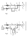
- Fig. 1 shows a first embodiment of an apparatus for continuously sampling a gas conduit 1, through which a gaseous flow possibly containing contaminations is conducted, of which the emission should be determined.
- the apparatus includes a probe 2 constructed as a straight tubing closed on one end and having an opposite open end 3 passed through the wall of the gas conduit 1 to be sampled and projecting a distance into the interior thereof.
- a tube-shaped supply line 4 supplies a flow V1 of clean dry medium controlled by a mass flow regulator 5 and serving as diluting gas.
- the supply line 4 passes through the closed end of the probe 2 and extends internally up to about 2/3 of the axial length of the probe and opens into the probe 2 in a location within the circumscription of the gas conduit 1.
- a tube-shaped discharge line 6 connects to the probe 2 near the closed end thereof and extends up to an analysis device 7 adapted to continuously analyse the diluted sample supplied by the discharge line 6.
- a further discharge line 8 such that the flow V2 of sample gas and the diluting gas from the probe 2 may flow from the discharge line 6 to the discharge line 8 through the analysis device 7.
- a mass flow regulator 9 Within the discharge line 8 is received a mass flow regulator 9, and to the end of the discharge line a vacuum pump 11 is connected effecting the withdrawal of sample gas and diluting gas from the probe.
- a flow of diluting gas having a delivery V1 and being accurately controlled by the mass flow regulator 5 is supplied to the probe 2 through the supply line 4. Simultaneously a flow of sample gas and diluting gas having a delivery V2 is withdrawn from the probe 2 by the vacuum pump 10 and is conducted through the discharge line 6 to the analysis device 7 and then to the mass flow regulator 9.
- This mass flow regulator 9 accurately controls the delivery V2 and is adjusted such that the delivery V2 of the gas flow withdrawn from the probe 2 is greater than the delivery V1 of the flow of diluting gas from the supply line 4, so that the flow of diluting gas in the probe 2 should be supplemented with a quantity of sample gas withdrawn from the gas conduit 1 through the probe 2.
- the delivery of the flow of sample gas withdrawn from the gas conduit 1, V3, is equal to the difference of the deliveries V2 and V1.
- the deliveries V1 and V2 are known in an accurate manner through the mass flow regulators 5 and 9 it is possible to calculate the delivery V3, for instance by means of a computer (not shown) connected to the mass flow regulators 5 and 9. With this information it is also possible to calculate the dilution factor of the sample, which is defined by:
- the values for the diluted sample measured by the analysis device 7 are converted to values of the undiluted sample with which the emission values of the gaseous flow through the gas conduit 1 are known.
- Fig. 2 shows a modified embodiment of the apparatus of fig. 1 which is adapted for batch sampling.
- the discharge line 6 communicates with a sampling bag 11 positioned within a vessel 12 in accordance with the so called “bag-in-bottle” principle.
- the discharge line 8 incorporating the mass flow regulator 9 and the vacuum pump 10.
- this apparatus is essentially similar to that of fig. 1 wherein, however, the vacuum pump 10 does not directly withdraw sample gas and diluting gas from the probe 2, but sucks gas from the vessel 12 with a delivery of V2, thereby expanding the bag and withdrawing sample gas and diluting gas with equal delivery V2 from the probe 2 through the discharge line 6 until the sample bag 11 is filled sufficiently. Due to the limited volume of the sampling bag 11 the sampling operation in this manner causes the development of start and stop phenomena at the beginning and end of the suction period of the vacuum pump 10. These phenomena are discounted in accordance with measured or calculated knowledge of the dynamic behaviour of the sampling apparatus by means of a mathematical model, for example stored in a computer which also has the values of the deliveries V1 and V2 during the suction period as input. In this manner the delivery V3 of the flow of sample gas from the gas conduit 1, and the eventually obtained dilution factor, respectively, can be determined in an accurate way.
- Fig. 3 shows an embodiment of a more complete apparatus for sampling the gas conduit 1 with which several samples can be taken simultaneously and which comprises control means to control the flows to the separate sampling means.
- the apparatus includes in the embodiment shown by way of example besides the sampling bag 7 an adsorption tube 13 adapted to adsorb substances from the sample gas for analysis purposes.
- the discharge line 6 is branched such that one branch leads to the sampling bag 7 and the other branch to the adsorption tube 13.
- the sampling bag 11 and the adsorption tube 13 are hence in parallel connection.
- a pump 14 connects to the supply line 4 for diluting gas, the pump 14 being adapted to suck diluting gas from a connection 15 through a filter 16. Between the pump 14 and the probe 2 are incorporated a mass flow regulator 17, an active carbon filter 18 and a connection 19. With these a clean, controlled flow of diluting gas can therefore flow to the probe 2.
- the discharge line 8 from the vessel 12 connects to a container 20, and in the line are incorporated another connection 21, a filter 22 and a mass flow regulator 23.
- a discharge line 24 comprising a connection 25, a filter 26 and a mass flow regulator 27 and thereafter communicating with the container 20.
- a vacuum pump 28 adapted to create a vacuum within the container 20 and to blow-off gas through a connection 29.
- the container 20 also includes an external vacuum connection 30 which is mostly closed by a small plug 31.
- the supply line 4 and the discharge line 8 are connected on a location between the mass flow regulator 17 or 23, respectively, and the probe 2, or the container 12, respectively, by means of a connection line having a valve 32.
- the pumps 14 and 28, the mass flow regulators 17, 23 and 27 and the valve 32 are connected with a micro-processor 33 containing a programme in which the steps of the sampling operation and the storage of all measuring values are registered.
- the computer further communicates with a display 34, a key board 35 and an external connection 36 for communication with any other computer.
- Diluting gas is sucked by the pump 14 from the connection 15 through the filter 16 and is supplied to the probe 2, wherein the mass flow regulator 17 accurately controls the delivery V1 of diluting gas.
- the pump 28 creates an underpressure in the container 20, thereby withdrawing sample gas and diluting gas from the probe 2, which flow is distributed to the sampling bag 11 and to the adsorption tube 13.
- the distribution of flows to the sampling bag 11 and the adsorption tube 13 depends on the adjustment of the mass flow regulators 23 and 27, wherein the sum of the deliveries through the mass flow regulators 23 and 27 is equal to the delivery of the sample gas and the diluting gas withdrawn from the probe 2.
- the diluting factor, the total quantity of sample gas of the sample taken, the volume of the diluted sample in the bag 11 and the delivery through the adsorption tube 13 can be calculated by the micro processor 33 on the basis of the measurement of the deliveries through the mass flow regulators 17, 23 and 27 and the sampling period.
- the work of the operator can be limited to a maximum extent by storing adjustments and procedures into algoritms controlling the sampling operation.
- the apparatus can be controlled such that prior to the start of the sampling operation the sampling bag 11 is pressed empty.
- the valve 32 is opened, while the mass flow regulator 17 causes a maximum passage of the flow of diluting gas supplied by the pump 14, and the mass flow regulators 23 and 27 are adjusted such that the flow therethrough is zero.
- the underpressure does not prevail instantly in the discharge line 6 as a result of the resistances and capacities of the parts of the apparatus through which gas flows. Due thereto the diluting factor is not constant during some period. In order to be able to calculate the total dilution factor in static or batch sampling operations, this is overcome by sucking only diluting gas during the period in which the underpressure is stabilized within the sampling bag 11.
- the invention provides an apparatus and method for sampling a gas conduit, wherein condensation and ad- and desorption of the sampling gas is prevented, calibration of the apparatus is redundant and a very accurate reproducible automatically controlled sampling operation is possible.
Landscapes
- Health & Medical Sciences (AREA)
- Life Sciences & Earth Sciences (AREA)
- Engineering & Computer Science (AREA)
- Biomedical Technology (AREA)
- Molecular Biology (AREA)
- Physics & Mathematics (AREA)
- Chemical & Material Sciences (AREA)
- Analytical Chemistry (AREA)
- Biochemistry (AREA)
- General Health & Medical Sciences (AREA)
- General Physics & Mathematics (AREA)
- Immunology (AREA)
- Pathology (AREA)
- Sampling And Sample Adjustment (AREA)
Applications Claiming Priority (2)
| Application Number | Priority Date | Filing Date | Title |
|---|---|---|---|
| NL8902871A NL8902871A (nl) | 1989-11-21 | 1989-11-21 | Werkwijze en inrichting voor het nemen van gasvormige monsters uit gaskanalen. |
| NL8902871 | 1989-11-21 |
Publications (1)
| Publication Number | Publication Date |
|---|---|
| EP0429143A1 true EP0429143A1 (fr) | 1991-05-29 |
Family
ID=19855663
Family Applications (1)
| Application Number | Title | Priority Date | Filing Date |
|---|---|---|---|
| EP90203081A Withdrawn EP0429143A1 (fr) | 1989-11-21 | 1990-11-21 | Méthode et dispositif pour prendre des échantillons gazeux de conduits de gaz |
Country Status (3)
| Country | Link |
|---|---|
| EP (1) | EP0429143A1 (fr) |
| JP (1) | JPH03176635A (fr) |
| NL (1) | NL8902871A (fr) |
Cited By (2)
| Publication number | Priority date | Publication date | Assignee | Title |
|---|---|---|---|---|
| EP0967473A1 (fr) * | 1998-06-25 | 1999-12-29 | Institut Francais Du Petrole | Procédé et unite de prelevement d'aldehydes et cetones contenus dans des gaz d'échappement |
| WO2005098392A1 (fr) * | 2004-04-09 | 2005-10-20 | Domenico Bruzzi | Sonde et systeme d'extraction de gaz d'un environnement de traitement |
Citations (1)
| Publication number | Priority date | Publication date | Assignee | Title |
|---|---|---|---|---|
| US4856352A (en) * | 1988-08-23 | 1989-08-15 | The Babcock & Wilcox Company | Gas sampling system for reactive gas-solid mixtures |
-
1989
- 1989-11-21 NL NL8902871A patent/NL8902871A/nl not_active Application Discontinuation
-
1990
- 1990-11-21 JP JP31761390A patent/JPH03176635A/ja active Pending
- 1990-11-21 EP EP90203081A patent/EP0429143A1/fr not_active Withdrawn
Patent Citations (1)
| Publication number | Priority date | Publication date | Assignee | Title |
|---|---|---|---|---|
| US4856352A (en) * | 1988-08-23 | 1989-08-15 | The Babcock & Wilcox Company | Gas sampling system for reactive gas-solid mixtures |
Non-Patent Citations (3)
| Title |
|---|
| CHEMICAL ENGINEERING, vol. 74, no. 14, 3rd July 1967, page 120; K. WASHIMI et al.: "Flushing nozzle with hydrogen solves sampling problem" * |
| PATENT ABSTRACTS OF JAPAN, vol. 9, no. 76 (P-346)[1799], 5th April 1985; & JP-A-59 206 741 (MITSUBISHI JUKOGYO K.K.) 22-11-1984 * |
| S.A.E. JOURNAL, vol. 77, no. 12, December 1969, pages 34-36; S.H. MICK et al.: "Use of constant-volume sampler to weigh exhaust emissions poses variety of problems" * |
Cited By (6)
| Publication number | Priority date | Publication date | Assignee | Title |
|---|---|---|---|---|
| EP0967473A1 (fr) * | 1998-06-25 | 1999-12-29 | Institut Francais Du Petrole | Procédé et unite de prelevement d'aldehydes et cetones contenus dans des gaz d'échappement |
| FR2780506A1 (fr) * | 1998-06-25 | 1999-12-31 | Inst Francais Du Petrole | Procede et unite de prelevement d'aldehydes et cetones contenus dans des gaz d'echappement |
| US6339965B1 (en) | 1998-06-25 | 2002-01-22 | Institut Francais Du Petrole | Process and unit for sampling aldehydes and ketones contained in exhaust gases |
| US6513397B2 (en) | 1998-06-25 | 2003-02-04 | Institut Francais Du Petrole | Process and unit for sampling aldehydes and ketones contained in exhaust gases |
| WO2005098392A1 (fr) * | 2004-04-09 | 2005-10-20 | Domenico Bruzzi | Sonde et systeme d'extraction de gaz d'un environnement de traitement |
| US7685894B2 (en) | 2004-04-09 | 2010-03-30 | Domenico Bruzzi | Probe and system for extracting gases from a process environment |
Also Published As
| Publication number | Publication date |
|---|---|
| NL8902871A (nl) | 1991-06-17 |
| JPH03176635A (ja) | 1991-07-31 |
Similar Documents
| Publication | Publication Date | Title |
|---|---|---|
| US5968452A (en) | System for controlling flow of a diluted sample and determining pollutants based on water content in engine exhaust emissions | |
| JP4517108B2 (ja) | 血餅その他の閉塞物の検出方法 | |
| JP4514174B2 (ja) | 自動検査システムにおける、吸引液量を検証する方法 | |
| US5237881A (en) | Inertial dilution filter probe | |
| US8531671B1 (en) | Apparatus and methods for determining the concentration of black carbon particles in a combustion exhaust | |
| US5965828A (en) | Fluid handler and method of handling a fluid | |
| EP0143837A1 (fr) | Porosimetre et procedes d'evaluation de la porosite. | |
| EP0983515A1 (fr) | Procede et dispositif de manipulation d'une fluide | |
| JPH07318555A (ja) | 全有機体炭素計 | |
| CN205246139U (zh) | 一种含气量测定仪 | |
| JP4081141B2 (ja) | 水分分析器 | |
| US6000397A (en) | Method and device for detecting a variation in a flowing medium | |
| EP0429143A1 (fr) | Méthode et dispositif pour prendre des échantillons gazeux de conduits de gaz | |
| US4348887A (en) | Apparatus for determining the effects of dilution and/or diffusion on the gaseous components of a gas flow | |
| JP3712761B2 (ja) | 液体試薬の容積測定方法 | |
| CA1219147A (fr) | Debitmetre pour liquides | |
| JPH107115A (ja) | 陰圧缶ヘッドスペースガス分析方法 | |
| US3163699A (en) | Sampling apparatus for flame photometer | |
| US4478080A (en) | Dewpoint measurement system for near saturation conditions | |
| CA1223451A (fr) | Appareil d'analyse aspirateur d'echantillons de gaz | |
| JP3006525U (ja) | 不飽和透水性測定装置 | |
| JP2592837B2 (ja) | 自動化学分析装置 | |
| CN208953525U (zh) | 一种地下水年龄的测定系统 | |
| JP2853603B2 (ja) | 定流量サンプリング装置 | |
| SU1054780A1 (ru) | Индикатор дл обнаружени и измерени концентрации газа |
Legal Events
| Date | Code | Title | Description |
|---|---|---|---|
| PUAI | Public reference made under article 153(3) epc to a published international application that has entered the european phase |
Free format text: ORIGINAL CODE: 0009012 |
|
| AK | Designated contracting states |
Kind code of ref document: A1 Designated state(s): AT BE CH DE DK ES FR GB GR IT LI LU NL SE |
|
| 17P | Request for examination filed |
Effective date: 19911129 |
|
| STAA | Information on the status of an ep patent application or granted ep patent |
Free format text: STATUS: THE APPLICATION HAS BEEN WITHDRAWN |
|
| 18W | Application withdrawn |
Withdrawal date: 19920713 |