EP0429194A2 - Assemblage à pile de disques à montage mécanique adaptatif - Google Patents
Assemblage à pile de disques à montage mécanique adaptatif Download PDFInfo
- Publication number
- EP0429194A2 EP0429194A2 EP90311840A EP90311840A EP0429194A2 EP 0429194 A2 EP0429194 A2 EP 0429194A2 EP 90311840 A EP90311840 A EP 90311840A EP 90311840 A EP90311840 A EP 90311840A EP 0429194 A2 EP0429194 A2 EP 0429194A2
- Authority
- EP
- European Patent Office
- Prior art keywords
- disk
- disk stack
- stack assembly
- ring
- cylindrical member
- Prior art date
- Legal status (The legal status is an assumption and is not a legal conclusion. Google has not performed a legal analysis and makes no representation as to the accuracy of the status listed.)
- Withdrawn
Links
Images
Classifications
-
- G—PHYSICS
- G11—INFORMATION STORAGE
- G11B—INFORMATION STORAGE BASED ON RELATIVE MOVEMENT BETWEEN RECORD CARRIER AND TRANSDUCER
- G11B17/00—Guiding record carriers not specifically of filamentary or web form, or of supports therefor
- G11B17/02—Details
- G11B17/038—Centering or locking of a plurality of discs in a single cartridge
-
- G—PHYSICS
- G11—INFORMATION STORAGE
- G11B—INFORMATION STORAGE BASED ON RELATIVE MOVEMENT BETWEEN RECORD CARRIER AND TRANSDUCER
- G11B25/00—Apparatus characterised by the shape of record carrier employed but not specific to the method of recording or reproducing, e.g. dictating apparatus; Combinations of such apparatus
- G11B25/04—Apparatus characterised by the shape of record carrier employed but not specific to the method of recording or reproducing, e.g. dictating apparatus; Combinations of such apparatus using flat record carriers, e.g. disc, card
- G11B25/043—Apparatus characterised by the shape of record carrier employed but not specific to the method of recording or reproducing, e.g. dictating apparatus; Combinations of such apparatus using flat record carriers, e.g. disc, card using rotating discs
-
- G—PHYSICS
- G11—INFORMATION STORAGE
- G11B—INFORMATION STORAGE BASED ON RELATIVE MOVEMENT BETWEEN RECORD CARRIER AND TRANSDUCER
- G11B33/00—Constructional parts, details or accessories not provided for in the other groups of this subclass
- G11B33/14—Reducing influence of physical parameters, e.g. temperature change, moisture, dust
- G11B33/1406—Reducing the influence of the temperature
- G11B33/1433—Reducing the influence of the temperature by reducing the effects of the thermal expansion
Definitions
- This invention relates generally to disk stack assemblies in disk memory drives in which permanent thermally induced relative displacements among the parts of the disk stack assembly are avoided.
- a significant problem in the design of a disk drive is how to deal with the broad temperature range in the thermal environment to which the disk drive may be exposed.
- Each part will expand or contract, depending upon the temperature swing experienced and on each materials, thermal coefficient of expansion. Great care must be taken where different materials are in contact. What may happen after one or more thermal cycles is that one of the parts will expand significantly more than the other and a slight slip will occur at the joint between the two parts. When returned to the original temperature, the parts will remain slightly displaced relative to their original positions.
- disk hub is made of steel and is actually a part of the motor rotor which drives the disk stack.
- the disk stack which is of aluminum is mounted on this steel hub.
- the thermal coefficients of expansion are different and in thermal cycling over the life of the disk drive, permanent relative displacement between the steel and the aluminum parts may occur.
- Any relative displacement, called disk slip results in a once around error in the track position. This once around error causes the servo to work harder in seeking or in following an eccentric track, for example, than it would otherwise have to work without the disk slip.
- the thermal mismatch in the materials for the situation dealt with here is between the aluminum disk and the disk spindle hub.
- Aluminum disks are commonly used in disk drives.
- Other parts of the drive structure may be made of steel to match the thermal coefficients of expansion among such parts and to obtain low thermal coefficients of expansion, the former to minimize or eliminate slippage at joints and the latter to minimize dimensional changes in changing thermal environments.
- the disk spindle hub is a steel cylinder forming part of the rotor of a motor driving the disk stack
- the aluminum disk stack it is not unusual for the aluminum disk stack to be mounted directly on the steel cylinder.
- Higher performance disk drives, with high track pitch and short seek times, are usually much more sensitive to the occurrence of physical displacements due to disk slip.
- Still another approach to joining an aluminum disk stack to a steel spindle hub is to shrink, or press, an aluminum sleeve over the steel hub.
- the interface of dissimilar materials is between the steel hub and the aluminum sleeve.
- the contact force due to the shrink or press fit is large enough that no slip occurs.
- minimum axial contact between the steel and aluminum cylinders is preferred because of the divergent thermal coefficients of expansion. This is a difficult assembly process.
- the compliant interface comprises a ring of material such as aluminum.
- the compliant ring is disposed between a bearing surface, such as an end flange on the steel cylindrical hub and a surface of a disk on one end of the disk stack.
- the aluminum ring has a cross sectional configuration affording radial compliance such that the bearing faces of the ring may move relative to one another without slippage at the flange or at the disk face.
- the disk stack of a material such as aluminum, having a thermal coefficient of expansion greater than that of the steel cylindrical hub, may radially expand and contract relative to the hub, during environmental thermal cycling, without interface slippage, which would cause permanent displacement. Disk eccentricity relative to the axis of rotation is thereby avoided.
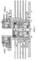
- a disk stack assembly embodying the principles of this invention is illustrated in the cross-sectional view of a disk stack assembly as seen in Fig. 1.
- the disk stack assembly is supported by a spindle shaft 1 secured in a spindle mounting flange 3, in turn secured to a base 5, forming part of the main frame of a disk drive.
- the spindle shaft 1 mounts the stator 7, having windings 8, of a motor generally designated 9, additionally comprising a rotor 11.
- the rotor 11 comprises a steel cylindrical hub 13, journalled by bearings 15 and 17 on opposite ends of the stator 7, on the spindle shaft 1, to rotate about the spindle axis.
- the steel cylindrical hub 13 mounts a permanent magnet cylinder 19 in a concentric position about the stator 7. Windings 7a of the motor 9 on the stator 7 are supplied with power by conductors (not shown) through the lower hollow section of the spindle shaft 1.
- a disk stack 21 comprises a plurality of axially spaced disks 21a, separated by spacers 21b. These spacers 21b and disks 21a are usually made of aluminum which has a thermal coefficient of expansion which is greater than that of the steel cylindrical hub 13. This disk stack has a central circular concentric opening of a diameter sufficient to provide clearance between the steel cylindrical hub 13 and the disk stack 21. The disk stack is located concentric to the spindle's axis of rotation and is securely clamped between the bottom flange 13a of the steel cylindrical hub 13 and a ring clamp 23 of aluminum at the upper end of the steel cylindrical hub 13.
- This compliant ring 25 has a T-shaped cross section and is disposed with the cross arm of the T, as the base 25a of the compliant ring 25, against the flange 13a, and the leg 25b of the T projecting upwardly, parallel to the axis of the spindle shaft 1.
- the axial leg 25b is of a cross section having a radial dimension and an axial dimension to provide long column stability to avoid buckling and yet within the elastic limits of the material of which it is fabricated, such as aluminum, to permit radial displacement of the upper end of the axial leg 25b with respect to its lower end, in the presence of thermal cycling in the disk drive environment, to accommodate radial displacement of the disk stack with respect to the steel cylindrical member 13 at the flange 13a, without slippage at the engaged surface and without exceeding the elastic limit of the material of the compliant ring 25, which would cause plastic deformation.
- Fig. 2 illustrates an alternative embodiment of this invention in which a compliant ring 25′ is of L-shaped cross sectional configuration. Otherwise the considerations discussed above with respect to the compliant ring 25 of T-shaped cross sectional configuration, apply equally here.
- Fig. 3 a further variation of the compliant ring is shown.
- the compliant ring 25 ⁇ in Fig. 3 comprises two axial legs dimensioned to provide stability in compression, yet individually of more flexibility in the radial direction than those of the Fig. 1 and Fig. 2.
- the compliant interface of the invention is useful in general in disk drives for joining the parts of disk stack assemblies where materials having different thermal coefficients of expansion are employed.
Landscapes
- Rotational Drive Of Disk (AREA)
- Holding Or Fastening Of Disk On Rotational Shaft (AREA)
Applications Claiming Priority (2)
| Application Number | Priority Date | Filing Date | Title |
|---|---|---|---|
| US43464889A | 1989-11-13 | 1989-11-13 | |
| US434648 | 1999-11-05 |
Publications (2)
| Publication Number | Publication Date |
|---|---|
| EP0429194A2 true EP0429194A2 (fr) | 1991-05-29 |
| EP0429194A3 EP0429194A3 (en) | 1992-01-15 |
Family
ID=23725072
Family Applications (1)
| Application Number | Title | Priority Date | Filing Date |
|---|---|---|---|
| EP19900311840 Withdrawn EP0429194A3 (en) | 1989-11-13 | 1990-10-29 | A mechanically compliant mount in a disk stack assembly |
Country Status (4)
| Country | Link |
|---|---|
| EP (1) | EP0429194A3 (fr) |
| JP (1) | JPH03207065A (fr) |
| BR (1) | BR9004893A (fr) |
| CA (1) | CA2021357A1 (fr) |
Cited By (1)
| Publication number | Priority date | Publication date | Assignee | Title |
|---|---|---|---|---|
| EP0959466A3 (fr) * | 1998-05-18 | 2000-07-19 | Fujitsu Limited | Appareil d'enregistrement de disques et disposittif de serrage pour cet appareil |
Family Cites Families (6)
| Publication number | Priority date | Publication date | Assignee | Title |
|---|---|---|---|---|
| US3587073A (en) * | 1969-08-21 | 1971-06-22 | Ibm | Clamp for attaching magnetic disks to a hub |
| US4205357A (en) * | 1978-06-15 | 1980-05-27 | Pertec Computer Corporation | Disk drive unit incorporating a field-replaceable fixed disk assembly |
| US4672488A (en) * | 1984-08-22 | 1987-06-09 | Wright Harold T | Spindle hub-disc interface |
| US4814652A (en) * | 1987-02-27 | 1989-03-21 | Maxtor Corporation | Disk drive motor with thermally matched parts |
| US4910620A (en) * | 1987-05-14 | 1990-03-20 | Siemens Aktiengesellschaft | Thermal compensation structure for a disk pack module |
| US4835637A (en) * | 1987-09-08 | 1989-05-30 | International Business Machines Corporation | Disk file with in-hub motor |
-
1990
- 1990-07-17 CA CA 2021357 patent/CA2021357A1/fr not_active Abandoned
- 1990-09-25 BR BR9004893A patent/BR9004893A/pt unknown
- 1990-10-29 EP EP19900311840 patent/EP0429194A3/en not_active Withdrawn
- 1990-11-13 JP JP30695190A patent/JPH03207065A/ja active Pending
Cited By (2)
| Publication number | Priority date | Publication date | Assignee | Title |
|---|---|---|---|---|
| EP0959466A3 (fr) * | 1998-05-18 | 2000-07-19 | Fujitsu Limited | Appareil d'enregistrement de disques et disposittif de serrage pour cet appareil |
| US6504674B2 (en) | 1998-05-18 | 2003-01-07 | Fujitsu Limited | Recording disk apparatus and clamp therefor |
Also Published As
| Publication number | Publication date |
|---|---|
| BR9004893A (pt) | 1991-09-10 |
| JPH03207065A (ja) | 1991-09-10 |
| EP0429194A3 (en) | 1992-01-15 |
| CA2021357A1 (fr) | 1991-05-14 |
Similar Documents
| Publication | Publication Date | Title |
|---|---|---|
| US4835637A (en) | Disk file with in-hub motor | |
| EP0429194A2 (fr) | Assemblage à pile de disques à montage mécanique adaptatif | |
| JP3318075B2 (ja) | スピンドルモータ | |
| JPH04184758A (ja) | ディスク駆動装置 | |
| JP2885214B2 (ja) | 磁気ディスク固定方法 | |
| JPH0520760A (ja) | 回転形記憶装置 | |
| JPH0448120Y2 (fr) | ||
| JP3985420B2 (ja) | スピンドルモータ | |
| KR100229391B1 (ko) | 헤드드럼 조립체 | |
| JPS59170524A (ja) | 気体軸受 | |
| JPH0416627Y2 (fr) | ||
| JP3050977B2 (ja) | 定位置予圧付加方法 | |
| JPS6069320A (ja) | ベアリング付きシヤフト・ユニット | |
| JPH06241229A (ja) | 磁気軸受 | |
| JP2882547B2 (ja) | 回転ヘッド装置の組立方法 | |
| JP2000230547A (ja) | ピボット軸受装置 | |
| JPH07296476A (ja) | 磁気ディスク装置 | |
| JPH11356026A (ja) | モ−タ及びその組立方法 | |
| JPH0787702A (ja) | スピンドルモータ | |
| JPH0254017B2 (fr) | ||
| JP2000004558A (ja) | モータおよびディスク駆動装置 | |
| JPS62239380A (ja) | 高精度回転体装置 | |
| JPH0644721A (ja) | 磁気ディスク装置 | |
| JPS61241524A (ja) | 軸受装置 | |
| JPH02226572A (ja) | 磁気ディスク装置およびその組立方法 |
Legal Events
| Date | Code | Title | Description |
|---|---|---|---|
| PUAI | Public reference made under article 153(3) epc to a published international application that has entered the european phase |
Free format text: ORIGINAL CODE: 0009012 |
|
| AK | Designated contracting states |
Kind code of ref document: A2 Designated state(s): DE FR GB IT |
|
| PUAL | Search report despatched |
Free format text: ORIGINAL CODE: 0009013 |
|
| AK | Designated contracting states |
Kind code of ref document: A3 Designated state(s): DE FR GB IT |
|
| 17P | Request for examination filed |
Effective date: 19920610 |
|
| 18W | Application withdrawn |
Withdrawal date: 19930602 |
|
| STAA | Information on the status of an ep patent application or granted ep patent |
Free format text: STATUS: THE APPLICATION HAS BEEN WITHDRAWN |
|
| R18W | Application withdrawn (corrected) |
Effective date: 19930602 |