EP0429277A1 - Ventilanordnung für eine Brennkraftmaschine - Google Patents
Ventilanordnung für eine Brennkraftmaschine Download PDFInfo
- Publication number
- EP0429277A1 EP0429277A1 EP90312569A EP90312569A EP0429277A1 EP 0429277 A1 EP0429277 A1 EP 0429277A1 EP 90312569 A EP90312569 A EP 90312569A EP 90312569 A EP90312569 A EP 90312569A EP 0429277 A1 EP0429277 A1 EP 0429277A1
- Authority
- EP
- European Patent Office
- Prior art keywords
- valve
- cam
- tubular
- shape
- axis
- Prior art date
- Legal status (The legal status is an assumption and is not a legal conclusion. Google has not performed a legal analysis and makes no representation as to the accuracy of the status listed.)
- Withdrawn
Links
- 238000002485 combustion reaction Methods 0.000 title claims abstract description 7
- 230000002093 peripheral effect Effects 0.000 claims description 2
- 238000000034 method Methods 0.000 description 2
- 230000007704 transition Effects 0.000 description 2
- 230000006835 compression Effects 0.000 description 1
- 238000007906 compression Methods 0.000 description 1
- 238000010276 construction Methods 0.000 description 1
- 230000003111 delayed effect Effects 0.000 description 1
- 230000008961 swelling Effects 0.000 description 1
Images

Classifications
-
- F—MECHANICAL ENGINEERING; LIGHTING; HEATING; WEAPONS; BLASTING
- F01—MACHINES OR ENGINES IN GENERAL; ENGINE PLANTS IN GENERAL; STEAM ENGINES
- F01L—CYCLICALLY OPERATING VALVES FOR MACHINES OR ENGINES
- F01L1/00—Valve-gear or valve arrangements, e.g. lift-valve gear
- F01L1/30—Valve-gear or valve arrangements, e.g. lift-valve gear characterised by the provision of positively opened and closed valves, i.e. desmodromic valves
-
- F—MECHANICAL ENGINEERING; LIGHTING; HEATING; WEAPONS; BLASTING
- F01—MACHINES OR ENGINES IN GENERAL; ENGINE PLANTS IN GENERAL; STEAM ENGINES
- F01L—CYCLICALLY OPERATING VALVES FOR MACHINES OR ENGINES
- F01L1/00—Valve-gear or valve arrangements, e.g. lift-valve gear
- F01L1/02—Valve drive
- F01L1/04—Valve drive by means of cams, camshafts, cam discs, eccentrics or the like
- F01L1/08—Shape of cams
-
- F—MECHANICAL ENGINEERING; LIGHTING; HEATING; WEAPONS; BLASTING
- F01—MACHINES OR ENGINES IN GENERAL; ENGINE PLANTS IN GENERAL; STEAM ENGINES
- F01L—CYCLICALLY OPERATING VALVES FOR MACHINES OR ENGINES
- F01L13/00—Modifications of valve-gear to facilitate reversing, braking, starting, changing compression ratio, or other specific operations
- F01L13/0015—Modifications of valve-gear to facilitate reversing, braking, starting, changing compression ratio, or other specific operations for optimising engine performances by modifying valve lift according to various working parameters, e.g. rotational speed, load, torque
- F01L13/0036—Modifications of valve-gear to facilitate reversing, braking, starting, changing compression ratio, or other specific operations for optimising engine performances by modifying valve lift according to various working parameters, e.g. rotational speed, load, torque the valves being driven by two or more cams with different shape, size or timing or a single cam profiled in axial and radial direction
- F01L13/0042—Modifications of valve-gear to facilitate reversing, braking, starting, changing compression ratio, or other specific operations for optimising engine performances by modifying valve lift according to various working parameters, e.g. rotational speed, load, torque the valves being driven by two or more cams with different shape, size or timing or a single cam profiled in axial and radial direction with cams being profiled in axial and radial direction
Definitions
- This invention relates to a valve arrangement for a combustion engine which can be used, for example, to drive the air intake and exhaust valves of a four stroke cycle engine.
- a valve arrangement for a combustion engine which has a cylinder with intake and exhaust ports each closed by a valve with each valve having a valve head and a valve stem guided for linear movement by a valve guide, characterised in that the valve is positively driven by a cam in both the opening and closing positions.
- a tubular cam is provided to drive at least one of the valves, the cam being arranged to rotate about an axis at right angles to the axis of movement of the valve, and the valve stem having a lateral recess in which the cam engages so that as the cam rotatesl the valve is moved in one or other direction in its valve guide.
- the lateral recess in the valve stem preferably includes two ball bearings, one of which runs against the outside of the tubular cam and the other of which runs around the inside of the tubular cam.
- the cam profile preferably varies along the axis of rotation of the cam, and the cam is also preferably mounted for axial movement.
- the shape of the tubular cam can allow a fully closed shape of the valve on the peripheral side, a low-speed rotation cam shape, a high-speed rotation cam shape, and a continuous fully open shape of the valve.
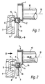
- a tubular cam 1 is mounted on the end of a shaft 10.
- the shaft 10 will rotate about its own axis 13 to produce rotation of the tubular cam 1.
- the cam surface itself passes through a recess 12 in a bracket 4 which forms part of the valve stem 3.
- a guide rod 6 connected to the bracket 4 runs in a vertical track 5 in part of a cylinder head.
- the bracket 4 (and hence the valve 9 and valve stem 3) follows the cam profile 1 through two ball bearings 2. One of these bearings runs against the inner periphery of the cam 1 and the other runs against the outer periphery. Because of the positioning of these two bearings, the valve 9 is constrained to follow precisely the profile of the cam 1 at all times. Note that in Figure 1, the cam profile is constant in an axial direction.
- Figure 2 shows an alternative cam construction where the profile of the cam varies over some of its circumference, in an axial direction. This creates at 1a, a low-speed rotational cam shape; at the other end 1b of the cam a high-speed rotational cam shape and a middle region 1c which provides medium-speed rotational cam shape.
- the transition between the areas 1a, 1b and 1c is smooth.
- the tubular cam 1 and the cam shaft 10 can be moved axially as indicated by a double-headed arrow 11. As the cam moves in this way, the ball bearings 2 will register with one of the cam regions 1a, 1b or 1c depending on the degree of axial movement. Because the transition between these regions is smooth, the axial movement can take place during rotational movement of the cam.
- the valve timing can therefore be varied in a stepless manner.
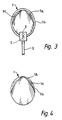
- FIGS 5, 6 and 7 show another form of tubular cam which has a circular outer form at le and a fully circular inner form at 1d. Between these two ends, in the intermediate position on both sides there is a low-speed rotation cam shape 1f swelling that is on the side of the low-speed rotation cam shape 1f, continuous to the egg-shaped low-speed rotation cam shape 1f, which leads into the high-speed rotation cam shape 1g.
- the cam 1 can be moved axially so that the ball bearings 2 follow any desired axial region of the cam.
- the apparatus described here has optimum performance as well as being simple to install and having reduced friction through reduction of the number of components.
- the tubular cam rotates as it is held between the inner and outer periphery of the tubular cam by the ball bearing mounted on the valve, and the valve stem is moved up and down to carry out the opening and closing operation. Since the opening and closing operation is directly linked to the valve stem and to the tubular cam, no effort needs to be made to achieve precise timing.
- the contact between the ball bearings 2 and the cam 1 is a point contact, it is a smooth contact with little friction.
Landscapes
- Engineering & Computer Science (AREA)
- Mechanical Engineering (AREA)
- General Engineering & Computer Science (AREA)
- Valve-Gear Or Valve Arrangements (AREA)
- Valve Device For Special Equipments (AREA)
Applications Claiming Priority (2)
| Application Number | Priority Date | Filing Date | Title |
|---|---|---|---|
| JP1305869A JPH03168307A (ja) | 1989-11-24 | 1989-11-24 | エンジンのバルブ駆動装置 |
| JP305869/89 | 1989-11-24 |
Publications (1)
| Publication Number | Publication Date |
|---|---|
| EP0429277A1 true EP0429277A1 (de) | 1991-05-29 |
Family
ID=17950332
Family Applications (1)
| Application Number | Title | Priority Date | Filing Date |
|---|---|---|---|
| EP90312569A Withdrawn EP0429277A1 (de) | 1989-11-24 | 1990-11-19 | Ventilanordnung für eine Brennkraftmaschine |
Country Status (3)
| Country | Link |
|---|---|
| US (1) | US5058540A (de) |
| EP (1) | EP0429277A1 (de) |
| JP (1) | JPH03168307A (de) |
Cited By (9)
| Publication number | Priority date | Publication date | Assignee | Title |
|---|---|---|---|---|
| GB2332710A (en) * | 1997-11-03 | 1999-06-30 | Craig Anthony Gager | A desmodromic gas exchange valve actuation arrangement |
| US6705262B2 (en) | 1998-06-16 | 2004-03-16 | Stefan Battlogg | Valve mechanism, in particular for internal combustion engines of motor vehicles |
| US6904882B2 (en) | 1999-08-12 | 2005-06-14 | Stefan Battlogg | Valve mechanism, in particular for internal combustion engines of motor vehicles |
| US6968814B2 (en) | 2002-03-28 | 2005-11-29 | Stefan Battlogg | Device for converting a rotational movement into a reciprocating movement |
| EP1624160A2 (de) | 2004-08-03 | 2006-02-08 | Stefan Battlogg | Zwangführungsvorrichtung zur Umwandlung der Drehbewegung eines Antriebs in eine hin- und hergehende Bewegung eines Teiles |
| EP1679428A1 (de) * | 2005-01-11 | 2006-07-12 | Fausto Pontinha Martins | Nockenwelle mit variablem Profil zur Betätigung der Ventile in dem Motorbrennraum. |
| EP1752620A1 (de) * | 2005-08-13 | 2007-02-14 | Dr. Ing. H.C.F. Porsche Aktiengesellschaft | Zwangsgesteuerter Ventiltrieb |
| EP1600610A3 (de) * | 2004-05-29 | 2008-08-20 | Dr. Ing. h.c. F. Porsche Aktiengesellschaft | Ventiltrieb für eine Brennkraftmaschine |
| US7421988B2 (en) | 2004-08-03 | 2008-09-09 | Stefan Battlogg | Positive-guidance apparatus for conversion of a rotary movement of a drive to a reciprocating movement of a part |
Families Citing this family (13)
| Publication number | Priority date | Publication date | Assignee | Title |
|---|---|---|---|---|
| CA2301298C (en) | 1999-03-19 | 2002-09-24 | Rodney J. Balzar | Drive train for overhead cam engine |
| US6276324B1 (en) | 1999-04-08 | 2001-08-21 | Tecumseh Products Company | Overhead ring cam engine with angled split housing |
| JP4499873B2 (ja) * | 2000-05-22 | 2010-07-07 | 株式会社オティックス | バルブリフタ及び動弁機構 |
| US7082912B2 (en) | 2001-03-16 | 2006-08-01 | Folino Frank A | System and method for controlling engine valve lift and valve opening percentage |
| US6953014B2 (en) | 2001-03-16 | 2005-10-11 | Folino Frank A | Thermal compensating desmodromic valve actuation system |
| US6619250B2 (en) * | 2001-03-16 | 2003-09-16 | Frank A. Folino | Desmodromic valve actuation system |
| WO2002081871A1 (de) * | 2001-04-09 | 2002-10-17 | Stefan Battlogg | Desmodromische ventiltrieb |
| EP1415069A1 (de) * | 2001-08-06 | 2004-05-06 | Stefan Battlogg | Vorrichtung zur umwandlung einer drehbewegung in eine hin- und hergehende bewegung |
| US6945206B1 (en) * | 2004-04-09 | 2005-09-20 | George Wayne Mobley | Lobe-less cam for use in a springless poppet valve system |
| US8622039B2 (en) | 2010-12-22 | 2014-01-07 | James T. Dougherty | Rockerless desmodromic valve system |
| US9366158B1 (en) | 2010-12-22 | 2016-06-14 | James T. Dougherty | Unitary cam follower and valve preload spring for a desmodromic valve mechanism |
| ES2690094B2 (es) * | 2017-05-18 | 2020-03-04 | Univ Cadiz | Arbol de levas de geometría variable con sistema desmodrómico |
| US12435650B2 (en) * | 2023-03-02 | 2025-10-07 | Anthony Strussione | No lash dual stem I.C.E. valve |
Citations (3)
| Publication number | Priority date | Publication date | Assignee | Title |
|---|---|---|---|---|
| US1937152A (en) * | 1930-12-23 | 1933-11-28 | Junk Walter | Positive valve control for internal combustion engines |
| EP0091804A1 (de) * | 1982-04-08 | 1983-10-19 | Jeffrey Robert Parker | Formschlüssiges Ventilantriebssystem |
| DE3706187A1 (de) * | 1987-02-26 | 1988-09-08 | Josef Austermann | Antriebsvorrichtung fuer ein vorzugsweise linear verstellbar gefuehrtes maschinenteil |
Family Cites Families (7)
| Publication number | Priority date | Publication date | Assignee | Title |
|---|---|---|---|---|
| GB434247A (en) * | 1934-10-20 | 1935-08-28 | John Fareso Senior | Valve operating mechanism |
| US2122484A (en) * | 1935-03-25 | 1938-07-05 | Frederick F Murray | Cooled valve |
| GB516746A (en) * | 1938-07-07 | 1940-01-10 | Cecil Newman James Glass | Improvements in or relating to valve actuating mechanisms for internal combustion engines |
| US4061115A (en) * | 1976-06-01 | 1977-12-06 | Predhome Jr Wilfred F | Valve train for internal combustion engine |
| US4711202A (en) * | 1986-10-30 | 1987-12-08 | General Motors Corporation | Direct acting cam-valve assembly |
| JPS63129109A (ja) * | 1986-11-17 | 1988-06-01 | Tsuneaki Takahashi | エンジンの動弁機構 |
| GB2202273B (en) * | 1987-03-18 | 1991-04-17 | Bothwell P W | Internal combustion engine |
-
1989
- 1989-11-24 JP JP1305869A patent/JPH03168307A/ja active Pending
-
1990
- 1990-11-19 EP EP90312569A patent/EP0429277A1/de not_active Withdrawn
- 1990-11-26 US US07/617,818 patent/US5058540A/en not_active Expired - Fee Related
Patent Citations (3)
| Publication number | Priority date | Publication date | Assignee | Title |
|---|---|---|---|---|
| US1937152A (en) * | 1930-12-23 | 1933-11-28 | Junk Walter | Positive valve control for internal combustion engines |
| EP0091804A1 (de) * | 1982-04-08 | 1983-10-19 | Jeffrey Robert Parker | Formschlüssiges Ventilantriebssystem |
| DE3706187A1 (de) * | 1987-02-26 | 1988-09-08 | Josef Austermann | Antriebsvorrichtung fuer ein vorzugsweise linear verstellbar gefuehrtes maschinenteil |
Cited By (11)
| Publication number | Priority date | Publication date | Assignee | Title |
|---|---|---|---|---|
| GB2332710A (en) * | 1997-11-03 | 1999-06-30 | Craig Anthony Gager | A desmodromic gas exchange valve actuation arrangement |
| US6705262B2 (en) | 1998-06-16 | 2004-03-16 | Stefan Battlogg | Valve mechanism, in particular for internal combustion engines of motor vehicles |
| US6796277B2 (en) | 1998-06-16 | 2004-09-28 | Stefan Battlogg | Valve mechanism, in particular for internal combustion engines of motor vehicles |
| US6802287B2 (en) | 1998-06-16 | 2004-10-12 | Stefan Battlogg | Valve mechanism, in particular for internal combustion engines |
| US6904882B2 (en) | 1999-08-12 | 2005-06-14 | Stefan Battlogg | Valve mechanism, in particular for internal combustion engines of motor vehicles |
| US6968814B2 (en) | 2002-03-28 | 2005-11-29 | Stefan Battlogg | Device for converting a rotational movement into a reciprocating movement |
| EP1600610A3 (de) * | 2004-05-29 | 2008-08-20 | Dr. Ing. h.c. F. Porsche Aktiengesellschaft | Ventiltrieb für eine Brennkraftmaschine |
| EP1624160A2 (de) | 2004-08-03 | 2006-02-08 | Stefan Battlogg | Zwangführungsvorrichtung zur Umwandlung der Drehbewegung eines Antriebs in eine hin- und hergehende Bewegung eines Teiles |
| US7421988B2 (en) | 2004-08-03 | 2008-09-09 | Stefan Battlogg | Positive-guidance apparatus for conversion of a rotary movement of a drive to a reciprocating movement of a part |
| EP1679428A1 (de) * | 2005-01-11 | 2006-07-12 | Fausto Pontinha Martins | Nockenwelle mit variablem Profil zur Betätigung der Ventile in dem Motorbrennraum. |
| EP1752620A1 (de) * | 2005-08-13 | 2007-02-14 | Dr. Ing. H.C.F. Porsche Aktiengesellschaft | Zwangsgesteuerter Ventiltrieb |
Also Published As
| Publication number | Publication date |
|---|---|
| JPH03168307A (ja) | 1991-07-22 |
| US5058540A (en) | 1991-10-22 |
Similar Documents
| Publication | Publication Date | Title |
|---|---|---|
| US6041746A (en) | Variable valve actuation apparatus | |
| US4522085A (en) | Variable lobe cam mechanism | |
| US5074260A (en) | Valve driving device and valve driving method for internal combustion engine | |
| JPH09506402A (ja) | 内燃エンジンの可変バルブリフト機構 | |
| US5058540A (en) | Engine valve driving device | |
| US6684832B1 (en) | Oscillating camshaft controlled valve operating device | |
| US4829949A (en) | Valve mechanism for an internal combustion engine | |
| KR20000071077A (ko) | 밸브 조정장치 | |
| JPH08506879A (ja) | 対称軸線から偏倚した点の周りにおける特殊な形のカムローブの角運動装置 | |
| EP1243765A1 (de) | Brennkraftmaschine mit variablem Ventilhub | |
| EP0434331A1 (de) | Ventilsteueranordnung für eine Brennkraftmaschine | |
| KR100666774B1 (ko) | 자동차의 가변 제어용 캠 구동 시스템 | |
| EP0838576A1 (de) | Variable Ventilsteuerungsvorrichtung für eine Brennkraftmaschine | |
| JP2004521245A (ja) | 可変バルブ機構 | |
| JP4051179B2 (ja) | 可変動弁機構 | |
| GB2201747A (en) | Speed change device and valve timing and actuating device | |
| JPH0755285Y2 (ja) | 4サイクルエンジンの動弁装置 | |
| JP2893748B2 (ja) | エンジンの弁作動装置 | |
| JPS61129411A (ja) | エンジンのバルブ動作可変機構 | |
| JPH03168309A (ja) | 4サイクルエンジンの弁開閉装置 | |
| KR20020047998A (ko) | 엔진의 가변식 밸브 구동 장치 | |
| JPH0130568Y2 (de) | ||
| KR960013355B1 (ko) | 자동차용 흡, 배기밸브 개폐 가변장치 | |
| JPH03160103A (ja) | 内燃機関における動弁装置 | |
| JPH0517107U (ja) | エンジンの動弁装置 |
Legal Events
| Date | Code | Title | Description |
|---|---|---|---|
| PUAI | Public reference made under article 153(3) epc to a published international application that has entered the european phase |
Free format text: ORIGINAL CODE: 0009012 |
|
| AK | Designated contracting states |
Kind code of ref document: A1 Designated state(s): DE FR GB IT |
|
| 17P | Request for examination filed |
Effective date: 19911018 |
|
| 17Q | First examination report despatched |
Effective date: 19920306 |
|
| STAA | Information on the status of an ep patent application or granted ep patent |
Free format text: STATUS: THE APPLICATION IS DEEMED TO BE WITHDRAWN |
|
| 18D | Application deemed to be withdrawn |
Effective date: 19920717 |