EP0429308A1 - Anlassvorrichtung mit Planetenuntersetzungsgetriebe - Google Patents
Anlassvorrichtung mit Planetenuntersetzungsgetriebe Download PDFInfo
- Publication number
- EP0429308A1 EP0429308A1 EP90312705A EP90312705A EP0429308A1 EP 0429308 A1 EP0429308 A1 EP 0429308A1 EP 90312705 A EP90312705 A EP 90312705A EP 90312705 A EP90312705 A EP 90312705A EP 0429308 A1 EP0429308 A1 EP 0429308A1
- Authority
- EP
- European Patent Office
- Prior art keywords
- internal gear
- gear
- housing
- starter apparatus
- rotary shaft
- Prior art date
- Legal status (The legal status is an assumption and is not a legal conclusion. Google has not performed a legal analysis and makes no representation as to the accuracy of the status listed.)
- Granted
Links
Images


Classifications
-
- F—MECHANICAL ENGINEERING; LIGHTING; HEATING; WEAPONS; BLASTING
- F02—COMBUSTION ENGINES; HOT-GAS OR COMBUSTION-PRODUCT ENGINE PLANTS
- F02N—STARTING OF COMBUSTION ENGINES; STARTING AIDS FOR SUCH ENGINES, NOT OTHERWISE PROVIDED FOR
- F02N15/00—Other power-operated starting apparatus; Component parts, details, or accessories, not provided for in, or of interest apart from groups F02N5/00 - F02N13/00
- F02N15/02—Gearing between starting-engines and started engines; Engagement or disengagement thereof
- F02N15/04—Gearing between starting-engines and started engines; Engagement or disengagement thereof the gearing including disengaging toothed gears
- F02N15/043—Gearing between starting-engines and started engines; Engagement or disengagement thereof the gearing including disengaging toothed gears the gearing including a speed reducer
- F02N15/046—Gearing between starting-engines and started engines; Engagement or disengagement thereof the gearing including disengaging toothed gears the gearing including a speed reducer of the planetary type
-
- Y—GENERAL TAGGING OF NEW TECHNOLOGICAL DEVELOPMENTS; GENERAL TAGGING OF CROSS-SECTIONAL TECHNOLOGIES SPANNING OVER SEVERAL SECTIONS OF THE IPC; TECHNICAL SUBJECTS COVERED BY FORMER USPC CROSS-REFERENCE ART COLLECTIONS [XRACs] AND DIGESTS
- Y10—TECHNICAL SUBJECTS COVERED BY FORMER USPC
- Y10S—TECHNICAL SUBJECTS COVERED BY FORMER USPC CROSS-REFERENCE ART COLLECTIONS [XRACs] AND DIGESTS
- Y10S74/00—Machine element or mechanism
- Y10S74/10—Polymer digest - plastic gears
-
- Y—GENERAL TAGGING OF NEW TECHNOLOGICAL DEVELOPMENTS; GENERAL TAGGING OF CROSS-SECTIONAL TECHNOLOGIES SPANNING OVER SEVERAL SECTIONS OF THE IPC; TECHNICAL SUBJECTS COVERED BY FORMER USPC CROSS-REFERENCE ART COLLECTIONS [XRACs] AND DIGESTS
- Y10—TECHNICAL SUBJECTS COVERED BY FORMER USPC
- Y10T—TECHNICAL SUBJECTS COVERED BY FORMER US CLASSIFICATION
- Y10T74/00—Machine element or mechanism
- Y10T74/13—Machine starters
- Y10T74/131—Automatic
- Y10T74/137—Reduction gearing
Definitions
- This invention relates to a starter apparatus with a planetary speed reduction gear and, more particularly, to a starter apparatus with a planetary speed reduction gear in which the rotation of a d.c. electric motor is transmitted through a planetary speed reduction gear mechanism to a pinion for driving an engine ring gear.
- Figs. 7 to 9 illustrate a conventional starter apparatus 1 with a planetary speed reduction gear
- the starter apparatus 1 comprises a d.c. electric motor 2, an over-running clutch 4 slidably placed over an output rotary shaft 3 connected to an armature rotary shaft of the d.c. electric motor 2 and a planetary speed reduction gear mechanism 5 which transmits, after speed-reducing, the rotational force of the armature rotary shaft through the output rotary shaft 3 to a clutch outer member of the over-running clutch 4.
- a shift lever 6 is provided to be driven by an unillustrated solenoid switch to cause a pinion 7 mounted to the output rotary shaft 3 to engage and disengage with respect to the engine ring gear.
- the planetary speed reduction gear mechanism 5 comprises an internal gear 10 made of a resin material and mounted to a housing 9 disposed on a front bracket 8, a spur gear 11 mounted to an armature rotary shaft and a plurality of planetary gears 12 in engagement with the internal gear 10 and the spur gear 11, and a planetary gear carrier 13 pivotally supporting the planetary gears 12 is connected to the output rotary shaft 3. Disposed between the d.c. motor 2 and the internal gear 10 is a packing 14.
- the internal gear deforms into a shape approximating a polygon having a number of sides corresponding to the number of planetary gears when a massive load is applied to the planetary speed reduction gear mechanism.
- the engagement between the planetary gears and the internal gear is shallow and the contact surface pressure is increased, so that the teeth of the gears are broken and the dedendum stress is increased because of the concentrated load on the tip of each tooth.
- one object of the present invention is to provide a starter apparatus with a planetary speed reduction gear free from the above discussed problems of the conventional design.
- Another object of the present invention is to provide a starter apparatus with a planetary speed reduction gear in which an internal gear of the planetary speed reduction gear does not disadvantageously deform with a large load.
- Another object of the present invention is to provide a starter apparatus with a planetary speed reduction gear in which an undesirable effect of heat generated within the planetary speed reduction gear is eliminated.
- the engine starter apparatus of the present invention comprises a housing, a d.c. electric motor attached to the housing and having an armature rotary shaft, an output rotary shaft with a pinion engageable with an engine ring gear, and a planetary speed reduction gear disposed within the housing between the armature rotary shaft and the output rotary shaft.
- the planetary speed reduction gear comprises a sun gear mounted to the armature rotary shaft, an internal gear made of a resin material and concentrically disposed around the sun gear with an annular space defined therebetween, a plurality of planetary gears disposed between the sun gear and the internal gear and each engaged with the sun gear and the internal gear, and a planetary gear carrier connected to the output rotary shaft and rotatably supporting the planetary gears.
- the internal gear comprises a ring-shaped internal gear member having an inner circumferential surface and an outer circumferential surface, and reinforcing member for elastically supporting the outer circumferential surface of the internal gear member, thereby to increase rigidity of the internal gear member.
- the reinforcing member comprises a thin-wall, substantially cylindrical member concentrically disposed around the internal gear member with an anulus defined therebetween, and a plurality of ribs radially and axially extending between the outer circumferential surface of the internal gear member and the cylindrical member for integrally connecting them together.
- Each of the ribs has a thickness which is substantially equal to a thickness of the thin-wall cylindrical member and smaller than a radial dimension of the internal gear member between the deddendum circle of the internal gear and the outer circumferential surface of the internal gear member.
- the thin wall cylindrical member and the housing may define therebetween a small radial gap which preferably is from 0.1 % to 0.5% of an outer diameter of the internal gear member.
- the ribs and the thin-wall cylindrical member have an axial length sufficient for covering at least an axial length corresponding to one half of an axial length of a meshing area in which the planetary gears are in mesh with the internal gear member, and a packing material may be filled between the other half of the axial length of the meshing area of the internal gear member and the housing.
- the reinforcing member may be an elastic ring member disposed between the outer circumferential surface of the internal gear member and the housing.
- the internal gear has a greater rigidity due to an elastic reinfcrcing member which may be ribs and a thin cylinder integrally molded to the internal gear member or an elastic packing material, so that the internal gear is prevented from being deformed even when a massive load is applied.
- an elastic reinfcrcing member which may be ribs and a thin cylinder integrally molded to the internal gear member or an elastic packing material
- FIGs. 1 to 4 illustrate one embodiment of the present invention, in which an engine starter apparatus comprises a hcusing 9, a d.c. electric motor 2 attached to the housing and having an armature rotary shaft 2a, an output rotary shaft 3 with a pinion 7 engageable with an engine ring gear (not shown), and a planetary speed reduction gear 5 disposed within the housing 9 between the armature rotary shaft 2a and the output rotary shaft 3.
- an engine starter apparatus comprises a hcusing 9, a d.c. electric motor 2 attached to the housing and having an armature rotary shaft 2a, an output rotary shaft 3 with a pinion 7 engageable with an engine ring gear (not shown), and a planetary speed reduction gear 5 disposed within the housing 9 between the armature rotary shaft 2a and the output rotary shaft 3.
- the planetary speed reduction gear 5 comprises a sun gear 11 mounted to the armature rotary shaft 2a, an internal gear 20 made of a resin material and concentrically disposed around the sun gear 11 with an annular space defined therebetween, a plurality of planetary gears 12 disposed between the sun gear 11 and the internal gear 20 and each engaged with the sun gear 11 and the internal gear 20, and a planetary gear carrier 13 connected to the output rotary shaft 3 and rotatably supporting the planetary gears 12.
- the internal gear 20 comprises a ring-shaped internal gear member 20a having an inner circumferential surface and an outer circumferential surface, and reinforcing member 20b for elastically supporting the outer circumferential surface of the internal gear member 20a, thereby to increase rigidity of the internal gear member 20a.
- the reinforcing member comprises a thin-wall, substantially cylindrical member 22 concentrically disposed around the internal gear member 20a with an anulus defined therebetween, and a large number of ribs 21 radially and axially extending between the outer circumferential surface of the internal gear member 20a and the cylindrical member 22 for integrally connecting them together.
- the internal gear member 20a made of a suitable resin material has integrally formed on its outer circumferential surface a large number of radial ribs 21, of which outer ends are integrally connected by a thin cylindrical member 22.
- the thickness of the radial ribs 21 is made substantially equal to the thickness a of the thin cylinder 22 and is made smaller than the dimension b between the outer diameter of the internal gear member 20a and the root of the ribs 21 (see Fig. 1). Also, it is desirable that a small clearance 22a is formed between the outer peripheral surface of the thin cylinder 22 and the inner surface of the housing 9
- This small clearance is preferably 0.1 ⁇ 0.5 % of the outer diameter of the internal gear 20.
- the axial length of the ribs 21 and the thin cylinder 22 are made longer than 1/2 of the length dimension over which they are in engagement with the planetary gears 12 and a packing 14 is provided at the step portion with no rib 21.
- the ribs 21 and the thin cylinder 22 reinforces the internal gear 20 to increase its strength by about 20%. Therefore, even if a massive load is applied to the planetary gear speed reduction means 5 upon the rotation of the armature rotary shaft, the deformation of the internal gear 20 is prevented and the internal gear 20 is not damaged.
- the frictional heat generated in the planetary gear speed reduction means 5 can be dissipated by conduction to the exterior because some of air gap is filled with the resin material, whereby the temperature rise in the internal gear 20 is suppressed, eliminating the fear that the internal gear 20 is damaged by heat.
- the small clearance defined by the housing 9 allows the internal gear 20 to deform by a suitable amount, ensuring uniform distribution of the load to prevent local damages by distributing the load. Also, an advantageous result is obtained that the internal gear 20 is prevented from being subjected to an abnormal force due to a difference in coefficient of thermal linear expansion upon the temperature change.
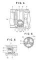
- Fig. 5 illustrates another embodiment, in which the internal gear 20 of the embodiment illustrated in Figs. 1 ⁇ 4, which has a cylinder thickness t of the gear portion, a plurality of notches 23a corresponding to spaces through which the through bolts pass are provided at equal intervals along the circumference.
- Fig. 6 illustrates one embodiment of the second invention, in which the internal gear 10 of the planetary speed reduction gear 5 which is similar to that of the conventional design has provided between the internal gear 10 and the housing 9 a cylindrical elastic member 24.
- the deformation and damage due to a large load can be prevented. Also, the damage of the internal gear by heat is prevented and the noise is advantageously reduced.
- the cylindrical elastic member is inserted between the internal gear member and the housing, so that the deformation of the internal gear member due to a large load can be prevented.
Landscapes
- Engineering & Computer Science (AREA)
- Chemical & Material Sciences (AREA)
- Combustion & Propulsion (AREA)
- Mechanical Engineering (AREA)
- General Engineering & Computer Science (AREA)
- Retarders (AREA)
- Connection Of Motors, Electrical Generators, Mechanical Devices, And The Like (AREA)
Applications Claiming Priority (2)
| Application Number | Priority Date | Filing Date | Title |
|---|---|---|---|
| JP1300816A JP2542093B2 (ja) | 1989-11-21 | 1989-11-21 | 遊星歯車式減速スタ―タ装置 |
| JP300816/89 | 1989-11-21 |
Publications (2)
| Publication Number | Publication Date |
|---|---|
| EP0429308A1 true EP0429308A1 (de) | 1991-05-29 |
| EP0429308B1 EP0429308B1 (de) | 1993-08-18 |
Family
ID=17889452
Family Applications (1)
| Application Number | Title | Priority Date | Filing Date |
|---|---|---|---|
| EP90312705A Expired - Lifetime EP0429308B1 (de) | 1989-11-21 | 1990-11-21 | Anlassvorrichtung mit Planetenuntersetzungsgetriebe |
Country Status (5)
| Country | Link |
|---|---|
| US (1) | US5157978A (de) |
| EP (1) | EP0429308B1 (de) |
| JP (1) | JP2542093B2 (de) |
| KR (1) | KR940010658B1 (de) |
| DE (1) | DE69002816T2 (de) |
Cited By (6)
| Publication number | Priority date | Publication date | Assignee | Title |
|---|---|---|---|---|
| DE4308914A1 (en) * | 1992-03-19 | 1993-09-23 | Hitachi Ltd | Planetary reduction gear and coaxial starter motor - has inner toothed wheel with thick walled section around closed end to increase strength |
| WO2005101622A1 (de) * | 2004-04-15 | 2005-10-27 | Keiper Gmbh & Co. Kg | Antriebseinheit eines einstellers in einem fahrzeug |
| US7294081B2 (en) | 2004-04-15 | 2007-11-13 | Keiper Gmbh & Co. Kg | Drive unit for a vehicle seat |
| US7329200B2 (en) | 2004-04-15 | 2008-02-12 | Keiper Gmbh & Co. Kg | Drive unit of an adjuster of a vehicle seat |
| US7345390B2 (en) | 2004-04-15 | 2008-03-18 | Keiper Gmbh & Co. Kg | Drive unit of an adjuster of a vehicle seat |
| US7544142B2 (en) | 2004-04-15 | 2009-06-09 | Keiper Gmbh & Co. Kg | Adjuster for a vehicle seat |
Families Citing this family (10)
| Publication number | Priority date | Publication date | Assignee | Title |
|---|---|---|---|---|
| JP2515602Y2 (ja) * | 1991-04-15 | 1996-10-30 | 三菱電機株式会社 | 遊星歯車減速スタータ装置 |
| JP2888407B2 (ja) * | 1993-10-18 | 1999-05-10 | 三菱電機株式会社 | 遊星歯車式トルク伝達装置 |
| JPH08291783A (ja) * | 1995-04-20 | 1996-11-05 | Mitsubishi Electric Corp | 遊星歯車減速スタータ装置 |
| US6109122A (en) * | 1998-11-10 | 2000-08-29 | Delco Remy International, Inc. | Starter motor assembly |
| US6630760B2 (en) | 2001-12-05 | 2003-10-07 | Delco Remy America, Inc. | Coaxial starter motor assembly having a return spring spaced from the pinion shaft |
| US6633099B2 (en) | 2001-12-05 | 2003-10-14 | Delco Remy America, Inc. | Engagement and disengagement mechanism for a coaxial starter motor assembly |
| JP2003207029A (ja) * | 2002-01-11 | 2003-07-25 | Koyo Seiko Co Ltd | 減速歯車機構及び電動式パワーステアリング装置 |
| KR100473977B1 (ko) * | 2002-07-27 | 2005-03-10 | 발레오전장시스템스코리아 주식회사 | 차량용 스타터 모터 |
| DE102010003431B4 (de) * | 2010-03-30 | 2019-05-16 | Seg Automotive Germany Gmbh | Startvorrichtung mit Hohlrad- und Zwischenlagerdämpfung |
| JP5363422B2 (ja) * | 2010-06-01 | 2013-12-11 | トヨタ自動車株式会社 | 車両用スタータリングギヤ |
Citations (2)
| Publication number | Priority date | Publication date | Assignee | Title |
|---|---|---|---|---|
| EP0188126A1 (de) * | 1984-12-20 | 1986-07-23 | Mitsubishi Denki Kabushiki Kaisha | Anlasser mit Planetengetriebe |
| GB2184787A (en) * | 1985-12-27 | 1987-07-01 | Magneti Marelli Spa | Starter device for i.c. engines |
Family Cites Families (9)
| Publication number | Priority date | Publication date | Assignee | Title |
|---|---|---|---|---|
| JPS5863361U (ja) * | 1981-10-24 | 1983-04-28 | 三菱電機株式会社 | 遊星歯車減速機付スタ−タ |
| JPS60184456U (ja) * | 1984-05-18 | 1985-12-06 | 三菱電機株式会社 | 歯車 |
| JPH027262Y2 (de) * | 1984-09-04 | 1990-02-21 | ||
| JPH027263Y2 (de) * | 1984-12-20 | 1990-02-21 | ||
| JPS61165656A (ja) * | 1985-01-18 | 1986-07-26 | Mitsubishi Electric Corp | 固定化酵素薄膜の形成法 |
| JPS61122377U (de) * | 1985-01-18 | 1986-08-01 | ||
| JPH0526309Y2 (de) * | 1986-02-24 | 1993-07-02 | ||
| JPS635161A (ja) * | 1986-06-25 | 1988-01-11 | Mitsubishi Electric Corp | 遊星歯車式減速スタ−タ |
| JPH01152068U (de) * | 1988-04-13 | 1989-10-19 |
-
1989
- 1989-11-21 JP JP1300816A patent/JP2542093B2/ja not_active Expired - Lifetime
-
1990
- 1990-09-18 KR KR1019900014726A patent/KR940010658B1/ko not_active Expired - Lifetime
- 1990-11-21 EP EP90312705A patent/EP0429308B1/de not_active Expired - Lifetime
- 1990-11-21 DE DE90312705T patent/DE69002816T2/de not_active Expired - Lifetime
-
1992
- 1992-06-02 US US07/892,628 patent/US5157978A/en not_active Expired - Lifetime
Patent Citations (2)
| Publication number | Priority date | Publication date | Assignee | Title |
|---|---|---|---|---|
| EP0188126A1 (de) * | 1984-12-20 | 1986-07-23 | Mitsubishi Denki Kabushiki Kaisha | Anlasser mit Planetengetriebe |
| GB2184787A (en) * | 1985-12-27 | 1987-07-01 | Magneti Marelli Spa | Starter device for i.c. engines |
Cited By (8)
| Publication number | Priority date | Publication date | Assignee | Title |
|---|---|---|---|---|
| DE4308914A1 (en) * | 1992-03-19 | 1993-09-23 | Hitachi Ltd | Planetary reduction gear and coaxial starter motor - has inner toothed wheel with thick walled section around closed end to increase strength |
| WO2005101622A1 (de) * | 2004-04-15 | 2005-10-27 | Keiper Gmbh & Co. Kg | Antriebseinheit eines einstellers in einem fahrzeug |
| US7294081B2 (en) | 2004-04-15 | 2007-11-13 | Keiper Gmbh & Co. Kg | Drive unit for a vehicle seat |
| US7329200B2 (en) | 2004-04-15 | 2008-02-12 | Keiper Gmbh & Co. Kg | Drive unit of an adjuster of a vehicle seat |
| US7345390B2 (en) | 2004-04-15 | 2008-03-18 | Keiper Gmbh & Co. Kg | Drive unit of an adjuster of a vehicle seat |
| US7544142B2 (en) | 2004-04-15 | 2009-06-09 | Keiper Gmbh & Co. Kg | Adjuster for a vehicle seat |
| US7544143B2 (en) | 2004-04-15 | 2009-06-09 | Keiper Gmbh & Co. Kg | Drive unit of an adjuster in a vehicle |
| CN1943096B (zh) * | 2004-04-15 | 2010-05-05 | 凯波有限责任两合公司 | 汽车中的调节器的驱动装置 |
Also Published As
| Publication number | Publication date |
|---|---|
| JPH03164567A (ja) | 1991-07-16 |
| DE69002816T2 (de) | 1994-03-31 |
| HK1005041A1 (en) | 1998-12-18 |
| US5157978A (en) | 1992-10-27 |
| DE69002816D1 (de) | 1993-09-23 |
| JP2542093B2 (ja) | 1996-10-09 |
| KR910010060A (ko) | 1991-06-28 |
| KR940010658B1 (ko) | 1994-10-24 |
| EP0429308B1 (de) | 1993-08-18 |
Similar Documents
| Publication | Publication Date | Title |
|---|---|---|
| EP0429308B1 (de) | Anlassvorrichtung mit Planetenuntersetzungsgetriebe | |
| EP0188126B1 (de) | Anlasser mit Planetengetriebe | |
| US6053060A (en) | Two-piece pinion gear | |
| KR910002120B1 (ko) | 유성 기어식 감속 시동기 | |
| KR100332136B1 (ko) | 시동 전동기 | |
| IE903144A1 (en) | Backlash free articulation reducing mechanism usable notably¹for the setting of the various portions of an automobile¹vehicle seat | |
| JP3499177B2 (ja) | スタータ | |
| JPH0146738B2 (de) | ||
| US5267918A (en) | Ring-shaped internal gear for epicyclic reduction gear type starter device | |
| US6276505B1 (en) | Multi-disk clutch | |
| US6076413A (en) | Motor vehicle starter with an epicyclic reducing gear train including a torque limiting device | |
| US5520273A (en) | Over-running clutch | |
| US6481553B1 (en) | Automatic transmission | |
| US6024197A (en) | Support structure for clutch hub | |
| EP0102037B1 (de) | Trommel für Lamellenkupplungseinheit | |
| HK1005041B (en) | Starter apparatus with planetary speed reduction gear | |
| US20020142881A1 (en) | Low noise planetary isolator | |
| US5746675A (en) | Carrier connecting structure for an automatic transmission | |
| US20070029151A1 (en) | Thrust washer to take torque converter axial loading | |
| US5477751A (en) | Clutch assembly for an automatic transmission | |
| CN112638685B (zh) | 用于车辆的驱动轮的轮毂装置 | |
| GB2329938A (en) | Starter motor drive stop for an electric starter motor | |
| EP0568019B1 (de) | Anlasserritzel für Verbrennungsmotor | |
| EP0947723A3 (de) | Kupplungsanordnung | |
| JP2658189B2 (ja) | 駆動円板装置の締結方法 |
Legal Events
| Date | Code | Title | Description |
|---|---|---|---|
| PUAI | Public reference made under article 153(3) epc to a published international application that has entered the european phase |
Free format text: ORIGINAL CODE: 0009012 |
|
| 17P | Request for examination filed |
Effective date: 19910102 |
|
| AK | Designated contracting states |
Kind code of ref document: A1 Designated state(s): DE FR GB IT |
|
| 17Q | First examination report despatched |
Effective date: 19920316 |
|
| GRAA | (expected) grant |
Free format text: ORIGINAL CODE: 0009210 |
|
| AK | Designated contracting states |
Kind code of ref document: B1 Designated state(s): DE FR GB IT |
|
| ITF | It: translation for a ep patent filed | ||
| REF | Corresponds to: |
Ref document number: 69002816 Country of ref document: DE Date of ref document: 19930923 |
|
| REG | Reference to a national code |
Ref country code: GB Ref legal event code: 727 |
|
| REG | Reference to a national code |
Ref country code: GB Ref legal event code: 727A |
|
| ET | Fr: translation filed | ||
| REG | Reference to a national code |
Ref country code: GB Ref legal event code: 727B |
|
| REG | Reference to a national code |
Ref country code: GB Ref legal event code: SP |
|
| PLBE | No opposition filed within time limit |
Free format text: ORIGINAL CODE: 0009261 |
|
| STAA | Information on the status of an ep patent application or granted ep patent |
Free format text: STATUS: NO OPPOSITION FILED WITHIN TIME LIMIT |
|
| 26N | No opposition filed | ||
| REG | Reference to a national code |
Ref country code: GB Ref legal event code: IF02 |
|
| PGFP | Annual fee paid to national office [announced via postgrant information from national office to epo] |
Ref country code: DE Payment date: 20091119 Year of fee payment: 20 |
|
| PGFP | Annual fee paid to national office [announced via postgrant information from national office to epo] |
Ref country code: IT Payment date: 20091118 Year of fee payment: 20 Ref country code: GB Payment date: 20091118 Year of fee payment: 20 Ref country code: FR Payment date: 20091123 Year of fee payment: 20 |
|
| REG | Reference to a national code |
Ref country code: GB Ref legal event code: PE20 Expiry date: 20101120 |
|
| PG25 | Lapsed in a contracting state [announced via postgrant information from national office to epo] |
Ref country code: GB Free format text: LAPSE BECAUSE OF EXPIRATION OF PROTECTION Effective date: 20101120 |
|
| PG25 | Lapsed in a contracting state [announced via postgrant information from national office to epo] |
Ref country code: DE Free format text: LAPSE BECAUSE OF EXPIRATION OF PROTECTION Effective date: 20101121 |