EP0429377B1 - Verstellbare Riemenscheibe einer Welle von einem KFZ-Motor und seine Verwendung - Google Patents
Verstellbare Riemenscheibe einer Welle von einem KFZ-Motor und seine Verwendung Download PDFInfo
- Publication number
- EP0429377B1 EP0429377B1 EP90420492A EP90420492A EP0429377B1 EP 0429377 B1 EP0429377 B1 EP 0429377B1 EP 90420492 A EP90420492 A EP 90420492A EP 90420492 A EP90420492 A EP 90420492A EP 0429377 B1 EP0429377 B1 EP 0429377B1
- Authority
- EP
- European Patent Office
- Prior art keywords
- hub
- rim
- pulley
- relative
- key
- Prior art date
- Legal status (The legal status is an assumption and is not a legal conclusion. Google has not performed a legal analysis and makes no representation as to the accuracy of the status listed.)
- Expired - Lifetime
Links
- 238000002347 injection Methods 0.000 claims abstract description 7
- 239000007924 injection Substances 0.000 claims abstract description 7
- 229910000831 Steel Inorganic materials 0.000 description 2
- 238000010586 diagram Methods 0.000 description 2
- 238000003754 machining Methods 0.000 description 2
- 239000010959 steel Substances 0.000 description 2
- 238000009825 accumulation Methods 0.000 description 1
- 238000002485 combustion reaction Methods 0.000 description 1
- 238000012937 correction Methods 0.000 description 1
- 230000002950 deficient Effects 0.000 description 1
- 230000000694 effects Effects 0.000 description 1
- 239000012530 fluid Substances 0.000 description 1
- 230000003100 immobilizing effect Effects 0.000 description 1
- 230000004048 modification Effects 0.000 description 1
- 238000012986 modification Methods 0.000 description 1
Images

Classifications
-
- F—MECHANICAL ENGINEERING; LIGHTING; HEATING; WEAPONS; BLASTING
- F02—COMBUSTION ENGINES; HOT-GAS OR COMBUSTION-PRODUCT ENGINE PLANTS
- F02M—SUPPLYING COMBUSTION ENGINES IN GENERAL WITH COMBUSTIBLE MIXTURES OR CONSTITUENTS THEREOF
- F02M59/00—Pumps specially adapted for fuel-injection and not provided for in groups F02M39/00 -F02M57/00, e.g. rotary cylinder-block type of pumps
- F02M59/44—Details, components parts, or accessories not provided for in, or of interest apart from, the apparatus of groups F02M59/02 - F02M59/42; Pumps having transducers, e.g. to measure displacement of pump rack or piston
-
- F—MECHANICAL ENGINEERING; LIGHTING; HEATING; WEAPONS; BLASTING
- F01—MACHINES OR ENGINES IN GENERAL; ENGINE PLANTS IN GENERAL; STEAM ENGINES
- F01L—CYCLICALLY OPERATING VALVES FOR MACHINES OR ENGINES
- F01L1/00—Valve-gear or valve arrangements, e.g. lift-valve gear
- F01L1/02—Valve drive
-
- F—MECHANICAL ENGINEERING; LIGHTING; HEATING; WEAPONS; BLASTING
- F01—MACHINES OR ENGINES IN GENERAL; ENGINE PLANTS IN GENERAL; STEAM ENGINES
- F01L—CYCLICALLY OPERATING VALVES FOR MACHINES OR ENGINES
- F01L1/00—Valve-gear or valve arrangements, e.g. lift-valve gear
- F01L1/02—Valve drive
- F01L1/024—Belt drive
-
- F—MECHANICAL ENGINEERING; LIGHTING; HEATING; WEAPONS; BLASTING
- F01—MACHINES OR ENGINES IN GENERAL; ENGINE PLANTS IN GENERAL; STEAM ENGINES
- F01L—CYCLICALLY OPERATING VALVES FOR MACHINES OR ENGINES
- F01L1/00—Valve-gear or valve arrangements, e.g. lift-valve gear
- F01L1/34—Valve-gear or valve arrangements, e.g. lift-valve gear characterised by the provision of means for changing the timing of the valves without changing the duration of opening and without affecting the magnitude of the valve lift
-
- F—MECHANICAL ENGINEERING; LIGHTING; HEATING; WEAPONS; BLASTING
- F02—COMBUSTION ENGINES; HOT-GAS OR COMBUSTION-PRODUCT ENGINE PLANTS
- F02M—SUPPLYING COMBUSTION ENGINES IN GENERAL WITH COMBUSTIBLE MIXTURES OR CONSTITUENTS THEREOF
- F02M39/00—Arrangements of fuel-injection apparatus with respect to engines; Pump drives adapted to such arrangements
- F02M39/02—Arrangements of fuel-injection apparatus to facilitate the driving of pumps; Arrangements of fuel-injection pumps; Pump drives
-
- F—MECHANICAL ENGINEERING; LIGHTING; HEATING; WEAPONS; BLASTING
- F16—ENGINEERING ELEMENTS AND UNITS; GENERAL MEASURES FOR PRODUCING AND MAINTAINING EFFECTIVE FUNCTIONING OF MACHINES OR INSTALLATIONS; THERMAL INSULATION IN GENERAL
- F16D—COUPLINGS FOR TRANSMITTING ROTATION; CLUTCHES; BRAKES
- F16D1/00—Couplings for rigidly connecting two coaxial shafts or other movable machine elements
- F16D1/12—Couplings for rigidly connecting two coaxial shafts or other movable machine elements allowing adjustment of the parts about the axis
-
- F—MECHANICAL ENGINEERING; LIGHTING; HEATING; WEAPONS; BLASTING
- F16—ENGINEERING ELEMENTS AND UNITS; GENERAL MEASURES FOR PRODUCING AND MAINTAINING EFFECTIVE FUNCTIONING OF MACHINES OR INSTALLATIONS; THERMAL INSULATION IN GENERAL
- F16H—GEARING
- F16H57/00—General details of gearing
- F16H57/0018—Shaft assemblies for gearings
- F16H57/0025—Shaft assemblies for gearings with gearing elements rigidly connected to a shaft, e.g. securing gears or pulleys by specially adapted splines, keys or methods
-
- F—MECHANICAL ENGINEERING; LIGHTING; HEATING; WEAPONS; BLASTING
- F01—MACHINES OR ENGINES IN GENERAL; ENGINE PLANTS IN GENERAL; STEAM ENGINES
- F01L—CYCLICALLY OPERATING VALVES FOR MACHINES OR ENGINES
- F01L2303/00—Manufacturing of components used in valve arrangements
- F01L2303/01—Tools for producing, mounting or adjusting, e.g. some part of the distribution
-
- F—MECHANICAL ENGINEERING; LIGHTING; HEATING; WEAPONS; BLASTING
- F01—MACHINES OR ENGINES IN GENERAL; ENGINE PLANTS IN GENERAL; STEAM ENGINES
- F01L—CYCLICALLY OPERATING VALVES FOR MACHINES OR ENGINES
- F01L2303/00—Manufacturing of components used in valve arrangements
- F01L2303/02—Initial camshaft settings
Definitions
- the invention relates to an adjustable pulley for driving an automotive shaft, for example driving a camshaft controlling an injection pump in an automotive mechanism.
- Such an adjustable pulley comprising a notched crown and a hub with 3 radial branches arranged in a star, the crown and the hub being secured by three screws and nuts, each screw passing through an elongated slot or lumen of the crown and a branch of the hub. These screws being loosened, the relative orientation of the hub and the crown can be adjusted by acting on a hexagonal relief carried by the center of the hub.
- This setting usually with an adjustable wrench, is qualitative and can only be used before assembly.
- the ribbed shaft driving the automobile mechanism, for example an injection pump is fixed to the hub which it passes through in a profiled opening in the center of this hub.
- This adjustable pulley, the crown and hub of which are secured after the relative orientation adjustment described above is usually driven by a toothed belt, different adjustable pulleys being able to succeed one another.
- the reliefs of the crown or pinion are the sides of an opening of this crown and the means which can bear on the hub so as to rotate on themselves in a fixed location of this hub consist of a special screw bolt carrying an eccentric cam and a hollow head in which an external key engages to turn this previously loosened bolt. The cam then bears against one side of the opening of the crown and rotates this crown.
- the Applicant has sought to develop an adjustable pulley avoiding such drawbacks.
- the subject of the invention is an adjustable pulley for driving a shaft of an automobile engine, for example a camshaft controlling an injection pump, this pulley comprising a crown as well as a hub adjustable in rotation to which said shaft is fixed and capable of being immobilized with respect to this crown, the means for relative rotation of the hub with respect to the crown comprising reliefs of this crown as well as means which can bear on said hub so as to rotate on themselves in a fixed location of this hub by cooperating with the reliefs of the crown and then producing a continuous relative and rotary movement of the hub relative to the crown, characterized in that said reliefs of the crown are a toothing carried by this crown and in that said means which can bear on the hub are a toothed key which can be fixed directly on the hub and then cooperate by its toothing with the toothing of the crown, said rotary movement giving a precise and reproducible adjustment of the relative orientation of the hub. It is therefore this key itself which produces the adjustment, in a particularly simple and convenient manner.
- the adjustable pulley of the cited document only allowed an imprecise adjustment of the relative orientation of the hub, and therefore of the cross section of the shaft fixed to this hub
- the adjustable pulley of the invention makes it possible to obtain a continuous, precise and reproducible adjustment of said relative orientation of the hub with respect to the crown by means of its toothed key.
- the use of this key of axis of rotation typically perpendicular to the front face of the hub then makes it possible to adjust or touch up the adjustment easily after assembly of the drive system.
- the precision and reproducibility of the adjustment are further improved and become excellent by writing or engraving graduations or marks on the two visible surfaces which move relative to each other during an adjustment: a portion of the crown and a portion of the hub.
- the fixing means in the adjustment position of the toothed key on the hub consists of a hole in this hub, in which engages the non-toothed lower end of this key for adjusting the relative rotation of said hub.
- This hole is blind, or more conveniently it passes through the hub, the bottom surface of the teeth of the key then coming to bear on the hub when this key rotates by driving the hub relative to the crown.
- the active surfaces of the teeth of the crown are parallel to the axis of symmetry and rotation of this crown and carried by its inner edge, while the toothing of the toothed key is parallel to its axis of rotation on itself and fits into the toothing of the crown, when the key is fixed in position on the hub for adjusting the rotation of the hub.
- This arrangement is best for machining or preparing the means concerned, namely: the toothing of the crown, the means for fixing or holding in position the key carried on the hub, and the toothed key itself.
- This arrangement also allows the easiest rotation, the corresponding force being perpendicular to the axis of rotation of the key.
- the hub often has 2 to 5, typically 3, substantially radial branches, their outline in the position of assembly with the crown protruding from the inside outline of this ring while the center of the hub is inside this inside outline.
- This arrangement is particularly advantageous for adjustments in position after assembly of the drive device.
- the means for immobilizing the hub with respect to the crown after the rotational adjustment consist of one or more circumferential openings or openings passing through the crown and of clamping means making it possible to secure the crown and the hub, for example in line with each light a hole for the passage of a screw passing through the hub as well as suitable screws and nut.
- These clamping means are slightly loosened to allow rotation during an adjustment, they are then tightened.
- the angular adjustments made either at the start, or in position with the adjustable pulley of the invention typically reach more or less 12 to 25 ° on either side of an average angular position of the hub, typically a position in which the axis of symmetry of a branch of this hub crosses the middle of a toothing of the crown.
- Figure 1 shows an adjustable pinion according to the invention in top view, its toothed key being shown without its head.
- FIG. 2 represents a toothed key used for adjusting the relative rotation of the pinion of FIG. 1.
- FIG. 3 represents the outline of the teeth of the crown of the pinion and of the key, in enlargement of a part of FIG. 1.
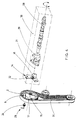
- Figure 4 shows part of a drive system comprising an adjustable pulley according to the invention, in partially exploded perspective.
- an adjustable pulley 1 comprising, on the one hand, a crown 2 of sintered steel carrying an external toothing 3 allowing it to be driven in rotation by a toothed belt and an inner flange or flange 4 comprising three wide portions 5, each comprising an elongated opening or circumferential opening 6, opening 6 of width 6.5 mm and average distance to the axis 13 of the crown 2 equal to 41 mm, allowing the passage of a screw 7 with head 8 to be blocked by a nut and three narrow intermediate portions 9 connecting with the neighboring wide portions.
- the crown 2 further comprises on the inner edge 10 of each wide portion 5 a toothing 11 whose tooth surfaces 12 are parallel to the axis of rotation 13 or ternary axis of symmetry of the crown 2.
- the addition of such toothing 11 (fig. 1 and 3) on a crown such that 2 is a simple modification, here produced by machining.
- the adjustable pulley 1 further comprises a hub 14, also made of sintered steel, having three branches 15 whose axes of symmetry 160 are radial, each branch 15 comprising near its end a through hole 60 of a screw such that 7.
- the screws 7 with head 8 and the corresponding nuts make it possible to secure the crown 2 and the hub 14 in a chosen relative orientation.
- the hub 14 has in its central portion 16 an additional thickness 17 of circumference 18 cylindrical hexagonal constituting a means for gripping the hub 14 to rotate it relative to the crown 2 when the nuts 8 are loosened.
- This extra thickness 17 of straight height 9.5 mm carries a frustoconical central hole 19 having a contour in circular cross section interrupted by the presence of a keyway 20, allowing the end of a shaft to be locked in position such that 21 (diagram of FIG. 4) in the opening 19.
- the distance from the axis of each hole 60 to the axis 130 of the hub 14 is 41 mm.
- Each hole 60 thus comes in front of an opening or opening 6 in the crown 2 whatever the relative orientation of the hub 14 relative to the crown 2, within the limits fixed by the circumferential extension of the openings 6.
- the position angular of the hub 14 relative to the crown 2 can vary here more or less 17 ° relative to the average position shown in FIG. 1.
- the hub 14 also comprises three through circular holes such as 22, of diameter 6 mm, centered on the axis of symmetry 16 of each of its branches 15 to 28.3 mm from the axis 130, these holes 22 used for fixing a toothed key 23, by embedding its lower portion 28 in a hole 22, the toothing 24 then coming to rest by its lower face on the front face of the hub 14 while interlocking with several of its teeth 25 in a toothing 11 in the form of a rack for the crown 2 (FIGS. 1 and 2).
- the profiles of the teeth 25 are thinned towards their ends so as to easily penetrate between the faces of the teeth 12 of the crown 2, and to fit over at least 70% of their length between these teeth 12 at the maximum of their engagement (FIG. 3).
- the outside diameter of the teeth 24 of the key 23 is here 11 mm, and the distance from the bottom of the teeth of the teeth 11 of the crown to the axis 13 of the crown 2 is 34 mm, which gives a good embedding of the teeth 24 and 11 and a continuous drive of the hub 14 relative to the crown 2 when the key 23 is rotated by means of its gripping portion or head 25 ( Figure 2).
- At least one branch 15 of the hub 14 -and preferably its three branches to adapt to any positions of the hub 14- has radial reference lines 26 making it possible to pinpoint the orientation obtained by relative to crown 2 bearing just behind its toothing 11 other radial reference lines 27. This arrangement allows an orientation adjustment and possible corrections of this more precise adjustment, and to obtain reproducible adjustments.
- This precise relative orientation adjustment can be made or corrected later by loosening the means 7 for fixing the hub 14 to the crown 2, relative orientation adjustment with the key 23 easily coming into position in a hole 22 by the sliding of its toothing 24 in the toothing 11 of the crown 2 which is chosen according to the position of this crown 2 and the operator's ease of access.
- the invention applies to the precise orientation adjustment of any shaft, typically a camshaft, having an effect on the operation of an automotive component, this component being for example a fluid supply or combustion device, again, for example, an injection pump.
Landscapes
- Engineering & Computer Science (AREA)
- General Engineering & Computer Science (AREA)
- Mechanical Engineering (AREA)
- Chemical & Material Sciences (AREA)
- Combustion & Propulsion (AREA)
- Pulleys (AREA)
- Transmissions By Endless Flexible Members (AREA)
- Transmission Devices (AREA)
- Devices For Conveying Motion By Means Of Endless Flexible Members (AREA)
- Fuel-Injection Apparatus (AREA)
Claims (8)
- Verstellbare Antriebsscheibe (1) einer Welle (21) in einem KFZ-Motor, wobei die Antriebsscheibe (1) einen Kranz (2) sowie eine drehverstellbare Nabe (14) aufweist, an der die Welle (21) befestigt ist und im Verhältnis zu diesem Kranz (2) verriegelt werden kann, wobei die Mittel zur relativen Drehung der Nabe (14) im Verhältnis zum Kranz (2) Erhöhungen (11) dieses Kranzes sowie Mittel (23) aufweisen, die sich auf die Nabe (14) abstützen können, so daß sie im Zusammenwirken mit den Erhöhungen (11) des Kranzes (2) um sich selbst an einer festgelegten Stelle (22) der Nabe (14) drehen und dann eine stetige relative Drehbewegung der Nabe im Verhältnis zum Kranz erzeugen, dadurch gekennzeichnet, daß die Erhöhungen (11) des Kranzes (2) eine von diesem Kranz (2) getragene Verzahnung (11) sind und daß die sich auf der Nabe (14) abstützenden Mittel (23) einen gezahnten Schlüssel (23) darstellen , die unmittelbar auf der Nabe (14) angebracht werden und dann mit dessen Verzahnung (24) und der Verzahnung (11) des Kranzes (2) zusammenwirken kann, wobei die Drehbewegung eine genaue und reproduzierbare Einstellung der relativen Ausrichtung der Nabe ergibt.
- Antriebsscheibe (1) nach Anspruch 1, bei welcher der gezahnte Schlüssel (23) ein unteres, nicht gezahntes Ende (28) aufweist und die Nabe (14) ein Loch (22) aufweist, in welches das untere Ende (28) für die Dreheinstellung der Nabe (14) eingreift.
- Antriebsscheibe (1) nach Anspruch 2, bei welcher die Verzahnung (24) des Schlüssels (23) eine untere Fläche aufweist, die sich auf der Nabe (14) abstützt, wenn sich der Schlüssel (23) für die Dreheinstellung der Nabe (14) um sich selbst dreht.
- Antriebsscheibe nach einem der Ansprüche 1 bis 3, bei welcher die Verzahnung (11) des Kranzes (2) zu dessen Achse (13) parallel ist und von dessen innerem Rand (10) getragen wird, wobei die Verzahnung des gezahnten Schlüssels (23) parallel zu dessen Drehachse um sich selbst ist und sich in die Verzahnung (11) des Kranzes (2) einfügt (einsetzt), wen der Schlüssel auf der Nabe (14) befestigt ist.
- Antriebsscheibe (1) nach einem der Ansprüche 1 bis 4, bei welcher Bezugsstriche (26; 27) einerseits von der Nabe (14) andereseits von dem Kranz (2) aufgebracht werden, um genaue Dreheinstellungen der Nabe (14) im Verhältnis zum Kranz (2) zu ermöglichen.
- Antriebsscheibe (1) nach einem der Ansprüche 1 bis 5, deren Nabe (14) 2 bis 5 radiale Schenkel (15) aufweist, wobei jeder Schenkel (15) und jeder dem jeweiligen Schenkel (15) gegenüberliegende Kranzabschnitt (5) zur mittleren relativen Ausrichtung der Nabe (14) je eine Verzahnung (11) und ein Befestigungsloch (22) eines gezahnten Schlüssels (23)aufweist, um die Dreheinstellung der Nabe (14) in verschiedenen Stellungen zu ermöglichen.
- Antriebsscheibe (1) nach einem der Ansprüche 1 bis 5, bei welcher die Verriegelungsmittel der Nabe (14) im Verhältnis zum Kranz (2) aus durch den Kranz (2) hindurchgehenden Umfangsschlitzen (6) und aus Spannmitteln (7 und 60) bestehen, mit welchen der Kranz (2) mit der Nabe (14) fest verbunden werden kann.
- Verwendung der einstellbaren Antriebsscheibe (1) nach einem der Ansprüche 1 bis 7 für den Antrieb einer Nockenwelle zur Steuerung einer Einspritzpumpe.
Priority Applications (1)
| Application Number | Priority Date | Filing Date | Title |
|---|---|---|---|
| AT90420492T ATE102305T1 (de) | 1989-11-17 | 1990-11-15 | Verstellbare riemenscheibe einer welle von einem kfz-motor und seine verwendung. |
Applications Claiming Priority (2)
| Application Number | Priority Date | Filing Date | Title |
|---|---|---|---|
| FR8915742A FR2654792A1 (fr) | 1989-11-17 | 1989-11-17 | Poulie reglable pour commande d'un organe mecanique ou hydraulique et son utilisation. |
| FR8915742 | 1989-11-17 |
Publications (2)
| Publication Number | Publication Date |
|---|---|
| EP0429377A1 EP0429377A1 (de) | 1991-05-29 |
| EP0429377B1 true EP0429377B1 (de) | 1994-03-02 |
Family
ID=9387934
Family Applications (1)
| Application Number | Title | Priority Date | Filing Date |
|---|---|---|---|
| EP90420492A Expired - Lifetime EP0429377B1 (de) | 1989-11-17 | 1990-11-15 | Verstellbare Riemenscheibe einer Welle von einem KFZ-Motor und seine Verwendung |
Country Status (5)
| Country | Link |
|---|---|
| EP (1) | EP0429377B1 (de) |
| AT (1) | ATE102305T1 (de) |
| DE (1) | DE69007026T2 (de) |
| ES (1) | ES2049447T3 (de) |
| FR (1) | FR2654792A1 (de) |
Cited By (1)
| Publication number | Priority date | Publication date | Assignee | Title |
|---|---|---|---|---|
| CN102767576A (zh) * | 2012-07-31 | 2012-11-07 | 无锡市大德科技有限公司 | 相位可调式联轴器 |
Families Citing this family (5)
| Publication number | Priority date | Publication date | Assignee | Title |
|---|---|---|---|---|
| FI92855C (fi) * | 1993-02-16 | 1995-01-10 | Waertsilae Diesel Int | Ison dieselmoottorin nokka-akselin säädettävä voimansiirtojärjestely |
| US5316522A (en) * | 1993-03-03 | 1994-05-31 | The Laitram Corporation | Axially-engaged, abrasion-resistant split sprocket assembly |
| FR2735526B1 (fr) * | 1995-06-13 | 1997-07-25 | Peugeot | Dispositif d'accouplement et de fixation d'un pignon a l'extremite d'un arbre |
| DE102005039460A1 (de) * | 2005-08-20 | 2007-02-22 | Daimlerchrysler Ag | Stellvorrichtung für eine Brennkraftmaschine, insbesondere Nockenwellenstellvorrichtung |
| DE102008059574A1 (de) * | 2008-11-28 | 2010-06-02 | Schaeffler Kg | Antriebsrad |
Family Cites Families (4)
| Publication number | Priority date | Publication date | Assignee | Title |
|---|---|---|---|---|
| GB192295A (en) * | 1922-02-15 | 1923-02-01 | Ellis Eckersley | A new or improved coupling or fine adjustment device |
| US3338112A (en) * | 1966-02-23 | 1967-08-29 | U S Baird Corp | Adjustable cam |
| US3490303A (en) * | 1968-03-26 | 1970-01-20 | Harold J Rosenberg | Driveshaft phase adjusting hub |
| US4096836A (en) * | 1977-01-19 | 1978-06-27 | General Motors Corporation | Variable timing device particularly for engine camshafts |
-
1989
- 1989-11-17 FR FR8915742A patent/FR2654792A1/fr active Granted
-
1990
- 1990-11-15 EP EP90420492A patent/EP0429377B1/de not_active Expired - Lifetime
- 1990-11-15 ES ES90420492T patent/ES2049447T3/es not_active Expired - Lifetime
- 1990-11-15 DE DE69007026T patent/DE69007026T2/de not_active Expired - Fee Related
- 1990-11-15 AT AT90420492T patent/ATE102305T1/de not_active IP Right Cessation
Cited By (2)
| Publication number | Priority date | Publication date | Assignee | Title |
|---|---|---|---|---|
| CN102767576A (zh) * | 2012-07-31 | 2012-11-07 | 无锡市大德科技有限公司 | 相位可调式联轴器 |
| CN102767576B (zh) * | 2012-07-31 | 2014-06-25 | 无锡市大德科技有限公司 | 相位可调式联轴器 |
Also Published As
| Publication number | Publication date |
|---|---|
| EP0429377A1 (de) | 1991-05-29 |
| FR2654792A1 (fr) | 1991-05-24 |
| ATE102305T1 (de) | 1994-03-15 |
| DE69007026T2 (de) | 1994-06-23 |
| FR2654792B1 (de) | 1994-12-16 |
| DE69007026D1 (de) | 1994-04-07 |
| ES2049447T3 (es) | 1994-04-16 |
Similar Documents
| Publication | Publication Date | Title |
|---|---|---|
| EP0217842B1 (de) | Tretlager für fahrrad oder für ähnliches fortbewegungsmittel | |
| FR2599697A1 (fr) | Dispositif de reception d'une colonne de direction d'un vehicule automobile | |
| FR2863027A1 (fr) | Mecanisme demultiplicateur, en particulier pour un dispositif de reglage d'un siege de vehicule automobile. | |
| EP0623485B1 (de) | Gelenkbeschlag für Kraftfahrzeugsitze | |
| EP0429377A1 (de) | Verstellbare Riemenscheibe einer Welle von einem KFZ-Motor und seine Verwendung | |
| FR2721868A1 (fr) | Garniture d'articulation pour un siege de vehicule raglable | |
| FR2655896A1 (fr) | Plateau multibroche d'usinage de configuration variable. | |
| FR2578601A1 (fr) | Articulation ronde sans satellite | |
| EP0621409A1 (de) | Befestigungseinrichtung zwischen einem Stütz- und Bewegungsteil sowie einem Werkzeug | |
| EP0686449A1 (de) | Spannbackenfutter | |
| EP0262048B1 (de) | Gerät zum automatischen Läppen von Elektroden von Schweissrobotern | |
| EP0240416B1 (de) | Antriebsvorrichtung zum relativen Verstellen von zwei Teilen, insbesondere für Fahrzeugsitze | |
| EP1244585B1 (de) | Befestigungsverfahren für einen kraftfahrzeugsflügel und vorrichtung für ein solches verfahren | |
| FR2759333A1 (fr) | Mecanisme d'articulation pour siege de vehicule, et siege de vehicule comportant un tel mecanisme | |
| FR2640461A1 (fr) | Mecanisme de fauchage rotatif a hauteur de coupe reglable | |
| EP1028005A1 (de) | Radialarmmarkiermaschine | |
| FR2765132A1 (fr) | Porte-outil equipe d'un dispositif de reglage | |
| EP0086243A1 (de) | Werkzeughaltevorrichtung, insbesondere für Universalwerkzeugmaschinen, vor allem zur Bearbeitung von kreisbogenförmigen Nuten | |
| FR2523818A1 (fr) | Dispositif de coupe pour tiges continues de produits a fumer | |
| FR2784135A1 (fr) | Charniere pour ouvrant de vehicule automobile | |
| FR3163418A1 (fr) | Tambour de frein a entraxe reglable | |
| FR2509249A1 (fr) | Pedale de bicyclette permettant l'accrochage d'une chaussure en position prereglee | |
| FR2576866A1 (fr) | Pedalier de bicyclette ou de machine analogue | |
| CH327821A (fr) | Machine à tailler les flancs et faces de dents de pignons coniques à dents droites ou à dents obliques | |
| FR2632217A1 (fr) | Dispositif et procede de fabrication d'une poulie a gorge a partir d'un disque circulaire en tole |
Legal Events
| Date | Code | Title | Description |
|---|---|---|---|
| PUAI | Public reference made under article 153(3) epc to a published international application that has entered the european phase |
Free format text: ORIGINAL CODE: 0009012 |
|
| AK | Designated contracting states |
Kind code of ref document: A1 Designated state(s): AT BE DE ES FR GB IT NL SE |
|
| 17P | Request for examination filed |
Effective date: 19910624 |
|
| RAP1 | Party data changed (applicant data changed or rights of an application transferred) |
Owner name: SINTERTECH |
|
| 17Q | First examination report despatched |
Effective date: 19920930 |
|
| GRAA | (expected) grant |
Free format text: ORIGINAL CODE: 0009210 |
|
| AK | Designated contracting states |
Kind code of ref document: B1 Designated state(s): AT BE DE ES FR GB IT NL SE |
|
| REF | Corresponds to: |
Ref document number: 102305 Country of ref document: AT Date of ref document: 19940315 Kind code of ref document: T |
|
| ITF | It: translation for a ep patent filed | ||
| GBT | Gb: translation of ep patent filed (gb section 77(6)(a)/1977) |
Effective date: 19940224 |
|
| REF | Corresponds to: |
Ref document number: 69007026 Country of ref document: DE Date of ref document: 19940407 |
|
| REG | Reference to a national code |
Ref country code: ES Ref legal event code: FG2A Ref document number: 2049447 Country of ref document: ES Kind code of ref document: T3 |
|
| PLBE | No opposition filed within time limit |
Free format text: ORIGINAL CODE: 0009261 |
|
| STAA | Information on the status of an ep patent application or granted ep patent |
Free format text: STATUS: NO OPPOSITION FILED WITHIN TIME LIMIT |
|
| EAL | Se: european patent in force in sweden |
Ref document number: 90420492.2 |
|
| 26N | No opposition filed | ||
| REG | Reference to a national code |
Ref country code: GB Ref legal event code: IF02 |
|
| PGFP | Annual fee paid to national office [announced via postgrant information from national office to epo] |
Ref country code: DE Payment date: 20071130 Year of fee payment: 18 Ref country code: ES Payment date: 20071126 Year of fee payment: 18 Ref country code: NL Payment date: 20071010 Year of fee payment: 18 |
|
| PGFP | Annual fee paid to national office [announced via postgrant information from national office to epo] |
Ref country code: IT Payment date: 20071116 Year of fee payment: 18 Ref country code: AT Payment date: 20071008 Year of fee payment: 18 |
|
| PGFP | Annual fee paid to national office [announced via postgrant information from national office to epo] |
Ref country code: BE Payment date: 20071212 Year of fee payment: 18 Ref country code: SE Payment date: 20071105 Year of fee payment: 18 |
|
| PGFP | Annual fee paid to national office [announced via postgrant information from national office to epo] |
Ref country code: FR Payment date: 20071105 Year of fee payment: 18 Ref country code: GB Payment date: 20071005 Year of fee payment: 18 |
|
| BERE | Be: lapsed |
Owner name: *SINTERTECH Effective date: 20081130 |
|
| EUG | Se: european patent has lapsed | ||
| GBPC | Gb: european patent ceased through non-payment of renewal fee |
Effective date: 20081115 |
|
| PG25 | Lapsed in a contracting state [announced via postgrant information from national office to epo] |
Ref country code: NL Free format text: LAPSE BECAUSE OF NON-PAYMENT OF DUE FEES Effective date: 20090601 |
|
| NLV4 | Nl: lapsed or anulled due to non-payment of the annual fee |
Effective date: 20090601 |
|
| PG25 | Lapsed in a contracting state [announced via postgrant information from national office to epo] |
Ref country code: AT Free format text: LAPSE BECAUSE OF NON-PAYMENT OF DUE FEES Effective date: 20081115 Ref country code: IT Free format text: LAPSE BECAUSE OF NON-PAYMENT OF DUE FEES Effective date: 20081115 |
|
| REG | Reference to a national code |
Ref country code: FR Ref legal event code: ST Effective date: 20090731 |
|
| PG25 | Lapsed in a contracting state [announced via postgrant information from national office to epo] |
Ref country code: BE Free format text: LAPSE BECAUSE OF NON-PAYMENT OF DUE FEES Effective date: 20081130 |
|
| PG25 | Lapsed in a contracting state [announced via postgrant information from national office to epo] |
Ref country code: DE Free format text: LAPSE BECAUSE OF NON-PAYMENT OF DUE FEES Effective date: 20090603 |
|
| PG25 | Lapsed in a contracting state [announced via postgrant information from national office to epo] |
Ref country code: GB Free format text: LAPSE BECAUSE OF NON-PAYMENT OF DUE FEES Effective date: 20081115 |
|
| REG | Reference to a national code |
Ref country code: ES Ref legal event code: FD2A Effective date: 20081117 |
|
| PG25 | Lapsed in a contracting state [announced via postgrant information from national office to epo] |
Ref country code: ES Free format text: LAPSE BECAUSE OF NON-PAYMENT OF DUE FEES Effective date: 20081117 |
|
| PG25 | Lapsed in a contracting state [announced via postgrant information from national office to epo] |
Ref country code: SE Free format text: LAPSE BECAUSE OF NON-PAYMENT OF DUE FEES Effective date: 20081116 |
|
| PG25 | Lapsed in a contracting state [announced via postgrant information from national office to epo] |
Ref country code: FR Free format text: LAPSE BECAUSE OF NON-PAYMENT OF DUE FEES Effective date: 20081130 |