EP1028005A1 - Radialarmmarkiermaschine - Google Patents
Radialarmmarkiermaschine Download PDFInfo
- Publication number
- EP1028005A1 EP1028005A1 EP00420026A EP00420026A EP1028005A1 EP 1028005 A1 EP1028005 A1 EP 1028005A1 EP 00420026 A EP00420026 A EP 00420026A EP 00420026 A EP00420026 A EP 00420026A EP 1028005 A1 EP1028005 A1 EP 1028005A1
- Authority
- EP
- European Patent Office
- Prior art keywords
- arm
- marking
- marking machine
- tool
- machine according
- Prior art date
- Legal status (The legal status is an assumption and is not a legal conclusion. Google has not performed a legal analysis and makes no representation as to the accuracy of the status listed.)
- Withdrawn
Links
Images


Classifications
-
- B—PERFORMING OPERATIONS; TRANSPORTING
- B44—DECORATIVE ARTS
- B44B—MACHINES, APPARATUS OR TOOLS FOR ARTISTIC WORK, e.g. FOR SCULPTURING, GUILLOCHING, CARVING, BRANDING, INLAYING
- B44B3/00—Artists' machines or apparatus equipped with tools or work holders moving or able to be controlled substantially two-dimensionally for carving, engraving, or guilloching shallow ornamenting or markings
- B44B3/06—Accessories, e.g. tool or work holders
- B44B3/061—Tool heads
Definitions
- the present invention relates to a marking machine.
- the invention relates more particularly to such a machine marking, comprising a frame on which is articulated a marking set. It applies to the realization of a pattern on the surface of a part, whether by printing, deformation or removal of material at this level area.
- This machine whose marking assembly is formed of two mutually articulated arms, however presents some disadvantages.
- the first arm has a weight high, insofar as it carries driving elements allowing the displacement of the second arm.
- these driving elements are placed in the vicinity of the end of this first arm opposite the frame, this induces a high moment of the marking assembly on the frame, detrimental to the good machine operation.
- the invention proposes to produce a marking machine allowing to overcome the drawbacks mentioned above.
- a marking machine comprising a frame, an arm articulated on said frame around a hinge pin, and a marking tool mounted mobile on said arm, characterized in that a single arm is provided and in that said machine further comprises means for translational movement of said marking tool relative said single arm.
- the marking machine As shown in Figure 1, the marking machine according to the invention, designated as a whole by the reference 2, includes a base 4 for receiving a part to mark not shown, base from which extends a vertical mast 6. A console or frame 8 is received on this mast 6, a handwheel 10 for adjusting, in a conventional manner, the height of this console 8 relative to the mast 6.
- the console 8 has a lower range 12, making projecting from the front of the mast 6.
- this case 14 provides housing to pivoting around axis A of a mobile marking assembly, designated by reference 16 and equipped with a marking tool 18.
- the track 12 supports a housing 20 interposed between the mast 6 and the chamber 14, which receives a motor, not shown, intended to ensure the pivoting of the marking assembly 16 compared to room 14.
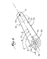
- all of marking 16 comprises a single elongated arm 22.
- This arm which is open towards the base 4, is provided with a veil upper 24 extended by a peripheral side wall 26.
- the marking assembly 16 also includes a chamber hollow 28, substantially cylindrical, pivotally mounted in the housing 14 and secured to the arm 22.
- a wheel tangent 30 is disposed on a shoulder 32 which is provided the outer wall of the chamber 28.
- This tangent wheel 30 cooperates with an endless screw 34, received in the housing 20 and actuated by a motor not shown.
- This worm comes into contact with the tangent wheel 30 through a notch 36 formed in the housing 14.
- the set of marking 16 is therefore free to pivot around the main axis A from room 28.
- the axial maintenance of the chamber 28 relative to the housing 14 is provided by means of an upper flange 38 attached around the chamber 28, cooperating with a inner shoulder 40 of the housing 14. Ball bearings or the like, not shown, are interposed between this flange 38 and this shoulder 40, in order to ensure pivoting easy housing compared to the room.
- Chamber 28 is closed at its upper part by a cover 42 disposed below a retaining circlip 44.
- a disc 46 is placed below the cover 42 and is supported, by its lower face, against a lower circlip 48.
- springs 50 interposed between the disc 46 and the cover 42, tend to push the latter against the upper circlip 44. In this first position, the cover 42 is secured in rotation, by friction on the circlip 44, to the assembly of marking.
- the cover 42 is integral with a rod 51 extending along the axis (A) and terminated by a handle 52.
- the end of this rod opposite the handle has a cooperating thread with a central thread formed in the disc 46.
- the cover is also integral with a lug 54 extending radially beyond the periphery of room 28. This tab is suitable for coming into line with a detector 56, for example at photoelectric cell, fixed to the housing 14.
- Chamber 28 is provided with a bottom 58 receiving a motor 60 whose output shaft, projecting downwards, is linked to a pinion 62 for actuating a toothed belt 64, forming a loop.
- This belt which extends axially over a major part of the length of the arm 22, surrounds, at its end opposite the pinion 62, a roller 66. The latter penetrates, by a axial finger 68, in a notch 70, formed in the web upper 24 of arm 22. The attachment of this finger 68 within this notch is ensured by a screw 72 passing through the wall peripheral 26.
- the belt 64 drives a carriage 74 carrying the tool marking 18.
- the belt and the carriage are for example secured by bonding.
- This carriage is hollowed out with a bore 76 crossed by a longitudinal guide bar 78 extending between the two ends of the peripheral web 24.
- This bore 76 is arranged in the direction of the tool 18, with respect to the belt 64.
- the carriage is further provided with an end bracket 80, opposite the tool, which overlaps a blade 82, intended avoid pivoting of the carriage and fixed on the upper wall of the web 24.
- the supply of the marking tool 18 is provided, in a known manner, by pneumatic means or not shown.
- the marking tool 18 can therefore be moved, relative to to a part to be marked, both under the effect of the pivoting of the arm 22 relative to the console 8 and under the effect of the translation of the carriage 74 relative to this arm 22.
- the position of the marking tool can be determined by using so-called polar coordinates, namely, on the one hand, the radial distance separating it from its point of origin in translation, which corresponds to its coming into abutment against an origin not shown secured to the arm and, on the other hand, the angle of the arm relative to the original position in rotation, in which the tab 54 is perpendicular to the detector 56.
- the invention makes it possible to achieve the objectives previously mentioned.
- the use of a single swivel arm, for ratio to which the marking tool is mobile in translation, guarantees greater ease of programming compared to prior art.
- the position of a point can be determined in polar coordinates, which is significantly more easier than taking into account two different angles, as in prior art.
- a determined point has only one pair of polar coordinates, which can be reached by means from a single position of the arm and the carriage, unlike prior art.
- the marking tool Since the marking tool is mobile in translation, it has a low inertia, which guarantees a satisfactory mobility. Marking done by machine of the invention can therefore be implemented more quickly than in the prior art.
- the marking tool is movable in translation compared to the single arm, the latter has a weight significantly reduced compared to the prior art, in the since it does not support any motor element at its end opposite to the frame, contrary to what exists in art prior.
- motor means allowing movement of the marking tool is also advantageous. Indeed, this characteristic allows to reduce very significantly, compared to art anterior, the moment of the arm on the frame of the machine.
Landscapes
- Manipulator (AREA)
Applications Claiming Priority (2)
| Application Number | Priority Date | Filing Date | Title |
|---|---|---|---|
| FR9901665 | 1999-02-09 | ||
| FR9901665A FR2789340B1 (fr) | 1999-02-09 | 1999-02-09 | Machine de marquage |
Publications (1)
| Publication Number | Publication Date |
|---|---|
| EP1028005A1 true EP1028005A1 (de) | 2000-08-16 |
Family
ID=9541916
Family Applications (1)
| Application Number | Title | Priority Date | Filing Date |
|---|---|---|---|
| EP00420026A Withdrawn EP1028005A1 (de) | 1999-02-09 | 2000-02-08 | Radialarmmarkiermaschine |
Country Status (5)
| Country | Link |
|---|---|
| US (1) | US6430820B1 (de) |
| EP (1) | EP1028005A1 (de) |
| JP (1) | JP2000229500A (de) |
| CA (1) | CA2298021A1 (de) |
| FR (1) | FR2789340B1 (de) |
Families Citing this family (6)
| Publication number | Priority date | Publication date | Assignee | Title |
|---|---|---|---|---|
| US6578276B2 (en) * | 1998-01-27 | 2003-06-17 | Eastman Kodak Company | Apparatus and method for marking multiple colors on a contoured surface having a complex topography |
| FR2849403A1 (fr) * | 2002-12-27 | 2004-07-02 | Gravograph Ind Internat | Machine a graver polaire |
| US8177443B2 (en) * | 2006-08-25 | 2012-05-15 | Tinnus Technology, Llc | Handheld pattern creating device and method of use of same |
| US7421790B1 (en) * | 2007-01-26 | 2008-09-09 | Gieseke Gerald G | Apparatus of and method of use of a radius table and radial template for forming muntin bar patterns for multi-pane window units with overlapping spokes |
| WO2010042791A1 (en) * | 2008-10-09 | 2010-04-15 | Making Memories | Hands free pattern creating device |
| CN112123312A (zh) * | 2020-09-18 | 2020-12-25 | 黄城明 | 一种料盘划线器 |
Citations (5)
| Publication number | Priority date | Publication date | Assignee | Title |
|---|---|---|---|---|
| US2950535A (en) * | 1957-02-25 | 1960-08-30 | George C Burgess | Lay out instrument |
| US3211061A (en) * | 1963-09-03 | 1965-10-12 | Hiram W Cretsinger | Carving attachment for radial arm saws |
| FR2677925A1 (fr) * | 1991-06-21 | 1992-12-24 | Therond Marcel | Dispositif de marquage pouvant marquer sur des surfaces etendues. |
| EP0586328A1 (de) * | 1992-09-02 | 1994-03-09 | Telesis Marking Systems, Inc. | Vorrichtung zum Kennzeichnen |
| US5667353A (en) * | 1995-03-31 | 1997-09-16 | Inspex Inc. | Robot system |
Family Cites Families (11)
| Publication number | Priority date | Publication date | Assignee | Title |
|---|---|---|---|---|
| US1113404A (en) * | 1912-12-18 | 1914-10-13 | Joseph H Blair | Drafting instrument. |
| US2219783A (en) * | 1939-01-24 | 1940-10-29 | Matson Taylor | Mechanical drawing apparatus |
| US2701417A (en) * | 1948-03-17 | 1955-02-08 | Graham Phillip | Graphic machine |
| US4709483A (en) * | 1984-03-14 | 1987-12-01 | Wing Aero | Glass cutting device |
| JPH0761759B2 (ja) * | 1988-02-05 | 1995-07-05 | 大日本スクリーン製造株式会社 | 自動製図機の描画具駆動装置 |
| SE462587B (sv) * | 1988-11-30 | 1990-07-23 | Wiklund Henry & Co | Anordning vid maerkning av arbetsstycken med skrift- eller andra tecken |
| US5079849A (en) * | 1990-09-06 | 1992-01-14 | Morris Nirenberg | Button and buttonhole marking machine |
| US5276970A (en) * | 1991-10-30 | 1994-01-11 | Hewlett-Packard Company | Codestrip in a large-format image-related device |
| US5507212A (en) * | 1994-01-14 | 1996-04-16 | Morrison; Gary | Radial arm saw glass cutting attachment |
| FR2723333B1 (fr) * | 1994-08-08 | 1996-09-20 | Technifor Sa | Dispositif de marquage pour la realisation de signes d'identification a deux dimensions sur la surface d'un objet quelconque |
| EP0931649A3 (de) * | 1998-01-27 | 2000-04-26 | Eastman Kodak Company | Gerät und Verfahren zum Bedrucken einer profilierten Oberfläche mit komplexer Topologie |
-
1999
- 1999-02-09 FR FR9901665A patent/FR2789340B1/fr not_active Expired - Fee Related
-
2000
- 2000-02-01 JP JP2000024291A patent/JP2000229500A/ja active Pending
- 2000-02-08 CA CA002298021A patent/CA2298021A1/fr not_active Abandoned
- 2000-02-08 US US09/499,750 patent/US6430820B1/en not_active Expired - Fee Related
- 2000-02-08 EP EP00420026A patent/EP1028005A1/de not_active Withdrawn
Patent Citations (5)
| Publication number | Priority date | Publication date | Assignee | Title |
|---|---|---|---|---|
| US2950535A (en) * | 1957-02-25 | 1960-08-30 | George C Burgess | Lay out instrument |
| US3211061A (en) * | 1963-09-03 | 1965-10-12 | Hiram W Cretsinger | Carving attachment for radial arm saws |
| FR2677925A1 (fr) * | 1991-06-21 | 1992-12-24 | Therond Marcel | Dispositif de marquage pouvant marquer sur des surfaces etendues. |
| EP0586328A1 (de) * | 1992-09-02 | 1994-03-09 | Telesis Marking Systems, Inc. | Vorrichtung zum Kennzeichnen |
| US5667353A (en) * | 1995-03-31 | 1997-09-16 | Inspex Inc. | Robot system |
Also Published As
| Publication number | Publication date |
|---|---|
| US6430820B1 (en) | 2002-08-13 |
| FR2789340A1 (fr) | 2000-08-11 |
| CA2298021A1 (fr) | 2000-08-09 |
| JP2000229500A (ja) | 2000-08-22 |
| FR2789340B1 (fr) | 2001-04-20 |
Similar Documents
| Publication | Publication Date | Title |
|---|---|---|
| EP0853527B1 (de) | Mess-und regelgerät für die bearbeitung von umlaufenden zylindrischen werkstücken | |
| FR2563861A1 (fr) | Dispositif de nettoyage de tarieres. | |
| EP1600730B1 (de) | Vorrichtung zum Abtasten von Konturen mittels einer drehenden beweglichen Prüfspitze | |
| FR2643053A1 (fr) | Dispositif d'entrainement de materiaux en bande, en plaque ou en fil | |
| EP0618089A1 (de) | Lenkrolle mit Richtungsverriegelung | |
| CA2298021A1 (fr) | Machine de marquage | |
| FR2658776A1 (fr) | Colonne de direction reglable. | |
| EP0700795B1 (de) | Markierungsgerät zum Aufbringen von Zweidimensionellen-Identifikationszeichen auf der Oberfläche eines Gegenstandes | |
| FR2501546A1 (fr) | Appareil pour former un trou a bord releve dans la paroi d'un tuyau | |
| EP0564372B1 (de) | Offsetdruckmaschine | |
| FR2673586A1 (fr) | Machine pour l'entretien d'une ligne de contact. | |
| EP1637655B1 (de) | Bodensäge | |
| FR2607107A1 (fr) | Rotor d'helicoptere | |
| FR2589098A1 (fr) | Machine pour le sciage semi-automatique de pieces de bois en vue de la realisation de buches de chauffage | |
| EP0299895A1 (de) | Einrichtung zum Freimachen von Geweben in Strangfärbemaschinen | |
| BE876794R (fr) | Appareil de commande automatique pour machine a scier les diamants | |
| FR2749789A1 (fr) | Dispositif de mesure ou de controle de l'usinage d'une piece cylindrique a mouvement orbital | |
| FR2583491A1 (fr) | Mecanisme de transmission, en particulier pour essuie-glace, et dispositif d'essuie-glace equipe d'un tel mecanisme | |
| EP0326501B1 (de) | Vorrichtung und Verfahren zum Positionieren eines Werkzeughalters entlang einer Achse | |
| FR2739585A1 (fr) | Dispositif de mesure ou de controle de l'usinage d'une piece cylindrique a mouvement orbital | |
| FR2634294A1 (fr) | Dispositif de commande a position neutre reglable | |
| BE535822A (de) | ||
| FR2493890A1 (fr) | Dispositif de fraisage, notamment pour revetements de sol | |
| FR2613805A2 (fr) | Systeme de commande d'un dispositif mecanique susceptible d'occuper plusieurs positions entre une position extreme d'ouverture et une position extreme de fermeture | |
| FR2739075A1 (fr) | Essuie-glace comportant des moyens pour faire varier la valeur du couple d'essuyage |
Legal Events
| Date | Code | Title | Description |
|---|---|---|---|
| PUAI | Public reference made under article 153(3) epc to a published international application that has entered the european phase |
Free format text: ORIGINAL CODE: 0009012 |
|
| AK | Designated contracting states |
Kind code of ref document: A1 Designated state(s): AT BE CH CY DE DK ES FI FR GB GR IE IT LI LU MC NL PT SE |
|
| AX | Request for extension of the european patent |
Free format text: AL;LT;LV;MK;RO;SI |
|
| 17P | Request for examination filed |
Effective date: 20000920 |
|
| AKX | Designation fees paid |
Free format text: AT BE CH CY DE DK ES FI FR GB GR IE IT LI LU MC NL PT SE |
|
| 17Q | First examination report despatched |
Effective date: 20020801 |
|
| GRAH | Despatch of communication of intention to grant a patent |
Free format text: ORIGINAL CODE: EPIDOS IGRA |
|
| STAA | Information on the status of an ep patent application or granted ep patent |
Free format text: STATUS: THE APPLICATION IS DEEMED TO BE WITHDRAWN |
|
| 18D | Application deemed to be withdrawn |
Effective date: 20030402 |