EP0429383A1 - Mähmaschine mit verbesserter Entlastungsvorrichtung - Google Patents
Mähmaschine mit verbesserter Entlastungsvorrichtung Download PDFInfo
- Publication number
- EP0429383A1 EP0429383A1 EP90440108A EP90440108A EP0429383A1 EP 0429383 A1 EP0429383 A1 EP 0429383A1 EP 90440108 A EP90440108 A EP 90440108A EP 90440108 A EP90440108 A EP 90440108A EP 0429383 A1 EP0429383 A1 EP 0429383A1
- Authority
- EP
- European Patent Office
- Prior art keywords
- harvesting mechanism
- mower according
- springs
- lightening
- members
- Prior art date
- Legal status (The legal status is an assumption and is not a legal conclusion. Google has not performed a legal analysis and makes no representation as to the accuracy of the status listed.)
- Granted
Links
Images


Classifications
-
- A—HUMAN NECESSITIES
- A01—AGRICULTURE; FORESTRY; ANIMAL HUSBANDRY; HUNTING; TRAPPING; FISHING
- A01D—HARVESTING; MOWING
- A01D43/00—Mowers combined with apparatus performing additional operations while mowing
- A01D43/10—Mowers combined with apparatus performing additional operations while mowing with means for crushing or bruising the mown crop
- A01D43/107—Mounting means
-
- A—HUMAN NECESSITIES
- A01—AGRICULTURE; FORESTRY; ANIMAL HUSBANDRY; HUNTING; TRAPPING; FISHING
- A01D—HARVESTING; MOWING
- A01D67/00—Undercarriages or frames specially adapted for harvesters or mowers; Mechanisms for adjusting the frame; Platforms
-
- Y—GENERAL TAGGING OF NEW TECHNOLOGICAL DEVELOPMENTS; GENERAL TAGGING OF CROSS-SECTIONAL TECHNOLOGIES SPANNING OVER SEVERAL SECTIONS OF THE IPC; TECHNICAL SUBJECTS COVERED BY FORMER USPC CROSS-REFERENCE ART COLLECTIONS [XRACs] AND DIGESTS
- Y10—TECHNICAL SUBJECTS COVERED BY FORMER USPC
- Y10S—TECHNICAL SUBJECTS COVERED BY FORMER USPC CROSS-REFERENCE ART COLLECTIONS [XRACs] AND DIGESTS
- Y10S56/00—Harvesters
- Y10S56/10—Uneven terrain compensation
Definitions
- the present invention relates to a mower comprising a chassis provided with a means of connection to a motor vehicle, at least one harvesting mechanism provided in particular with cutting members and connected to said chassis by a suspension device which allows a displacement in height of said harvesting mechanism with respect to said chassis, and a lightening device associated with said harvesting mechanism comprising at least one spring linked directly to the harvesting mechanism.
- a trailed mower comprising a frame which extends transversely to the direction of advance to work. At each of its ends, this chassis is provided with a wheel through which it rests on the ground. In the middle part, the chassis is provided with a drawbar which makes it possible to couple the mower to a tractor and which is linked to the chassis by an articulation of an axis directed at least substantially vertically.
- the chassis supports a harvesting mechanism by means of a deformable parallelogram suspension device. This device comprises two pairs of connecting rods each extending near one end of the chassis, respectively of the harvesting mechanism. Between the harvesting mechanism and the chassis further extends a device for lightening said harvesting mechanism.
- This lightening device comprises two tension springs each extending near one end of the chassis, respectively of the cutting mechanism, in front of the corresponding pair of connecting rods of the deformable parallelogram suspension device.
- Each tension spring is linked directly to the harvesting mechanism by means of a screw passing through a tab integral with the harvesting mechanism and screwed into a connecting piece integral with said spring. By screwing the screw more or less deeply into the spring connection piece, the spring is more or less lengthened, which makes it possible to adjust the desired lightening at the corresponding end of the harvesting mechanism.
- the deformable parallelogram suspension device the harvesting mechanism can move in height with respect to the chassis, in order to adapt to the configuration of the terrain and to pass over obstacles that the terrain may present.
- the lightening device reduces the pressure with which the harvesting mechanism rests on the ground, by transferring part of the weight of the harvesting mechanism on the chassis. Thanks to this device, the harvesting mechanism passes more easily over obstacles that the ground presents. Since the harvesting mechanism rests less heavily on the ground, this also results in a reduction in the power required to move the mower.
- the harvesting mechanism comprises a support beam extending under the cutting members by supporting them and sliding on the ground, it finally makes it possible to reduce the risks of accumulations of soil at the front part of said beam support.
- the advantage of the lightening device of this known mower lies in the fact that the springs are directly linked to the harvesting mechanism. This in fact allows the lightening device to work with extremely short response times.
- the present invention aims to create a mower whose lightening device better alleviates the harvesting mechanism, while retaining the advantage of very short response time.
- the mower according to the present invention is characterized in that the lightening device extends at least substantially in the vicinity of the vertical plane directed in the direction of advance to work and containing the center of the masses of the mechanism harvest.
- the lightening device Since in the mower according to the invention, the lightening device is directly linked to the harvesting mechanism, said lightening device works with very short response times.
- the lightening device extends, in addition, at least substantially in the vicinity of the vertical plane directed in the direction of advance to work and containing the center of the masses of the harvesting mechanism, the pressures with which the two ends of the harvesting mechanism resting on the ground are equal or at least very close to each other.
- the lightening device to extend behind the cutting members and to be linked to said harvesting mechanism in the vicinity of the cutting plane of the cutting members. Thanks to this characteristic, the said spring or springs of the lightening device can have a great length. As a result, their deformation diagram is relatively flat. They therefore allow a large displacement in height of the harvesting mechanism relative to the chassis.
- an advantageous solution consists in providing that, in front of the lightening device, the harvesting mechanism is provided with two rotors each rotating around an axis directed upwards and in such a way that their respective directions of rotation diverge forward.
- said coupling element is stiffened by means of a stiffening member.
- this stiffening member is linked on the one hand to the harvesting mechanism by means of a first articulation extending above the cutting members, and on the other hand to the coupling element at by means of a second articulation. A triangulation is thus formed which gives the coupling element great rigidity.
- the lightening device is linked to the harvesting mechanism by an articulation, preferably cylindrical, of axis at least substantially horizontal and at least substantially perpendicular to the direction of advance to work.
- This type of connection leads, on the one hand, to even shorter response times and on the other hand prevents, in the case of tension springs, the bending of the latter.
- the second articulation by means of which the stiffening member is linked to the coupling element ment, or at least substantially coincident with said articulation.
- the lightening device prefferably be provided with a device for adjusting the lightening force exerted on the harvesting mechanism.
- the lightening device comprises a group of springs, part of which extends on one side of the vertical plane directed in the direction of advance to work and containing the center of the masses of the harvesting mechanism, and the other part of which extends on the other side of said plane.
- these two parts are identical.
- the adjustment device in particular to comprise a screw and nut device.
- This screw extends at least substantially parallel to the springs and is linked to the chassis. It is also screwed into a nut linked to the common connecting piece.
- the screw has a spherical bearing face intended to come in contact with a bearing surface of the chassis also spherical.
- the nut also includes a spherical bearing face intended to come into contact with a spherical bearing face of the common connecting piece.
- This articulation has the effect, when the harvesting mechanism is tilted relative to the frame sis, transverse to the direction of advance to work, to allow the common connecting piece to pivot to substantially equalize the forces created by the two parts of the group of springs on the harvesting mechanism.
- the harvesting mechanism comprises drive elements which include in particular an input shaft receiving the movement by means of a telescopic transmission shaft with universal joints which passes between the two parts of the group of springs.
- the harvesting mechanism further comprises processing members extending behind the cutting members, for the purpose of processing the product cut by the cutting members.
- said processing members comprise two groups of processing members extending on either side of the vertical median plane of the harvesting mechanism, directed in the direction of advance to work.
- the two groups of treatment members Preferably, moreover, provision will be made for the two groups of treatment members to extend at least substantially symmetrically with respect to said plane.
- the lightening device of the harvesting mechanism can thus extend between these two groups of processing members.
- FIG. 1 shows a mower (1) according to the invention. This is coupled to an agricultural tractor (2).
- the drawbar (4) consists of a body (3) and a drawbar (4).
- the drawbar (4) for its part, consists of a primary drawbar (5) intended to be coupled to the lower arms (6) of the coupling of the agricultural tractor (2) and a secondary drawbar (7) linked to the body (3) of the mower (1).
- the primary drawbar (5) is linked to the front end of the secondary drawbar (7) by means of a connecting device (8) known to those skilled in the art and which allows in particular a pivoting of the primary drawbar (5 ) relative to the secondary drawbar (7) about an axis at least substantially vertical.
- the secondary drawbar (7) is linked to the body (3) by means of an articulation (9) of geometric axis (10) (see FIG.
- the body (3) of the mower (1) can, in particular at work, extend - seen from the rear in the direction of advance (12) at work - either to the right or to the left of the agricultural tractor (2). This allows mowing back and forth.
- the body (3) of the mower (1) comprises a chassis (14) which rests on the ground - especially at work - by means of two wheels (15) which each extend near a respective outer end of said chassis (14).
- Each wheel (15) is linked to the chassis (14) by means of a wheel arm (16) itself linked to said chassis (14) by means of a pivot type hinge (17) with a geometric axis directed at less substantially perpendicular to the direction of advance (12) at work.
- the geometric axes of the articulations (17) of the two wheels (15) are at least substantially coincident.
- Between each wheel arm (16) and the chassis (14) is also provided a hydraulic cylinder (18) which allows the wheel arm (16) and the corresponding wheel (15) to pivot relative to the chassis (14). around the geometric axis of the corresponding articulation (17). This allows the chassis (14) to be approached from the ground (109) during the mowing phase and to be moved away from the ground (109) when the mowing is interrupted.
- the body (3) of the mower (1) further comprises a group of working members which is here constituted by a harvesting mechanism (19) provided with cutting members (20) and processing members (21) of the product cut by the cutting members (20), such as organs conditioning for example.
- This harvesting mechanism (19) is linked to the chassis (14) by means of a suspension device (22) and a lightening device (64), which will be described later.
- the harvesting mechanism (19) is driven from the PTO (23) of the tractor (2) which attacks, via a telescopic universal joint shaft (24) input (not shown) of the connecting device (8) which is also, in a manner known to those skilled in the art, a movement transmission device.
- the output shaft (25) of the link and transmission device (8) transmits the movement to a transmission shaft (26) which is housed inside the secondary drawbar (7).
- the transmission shaft (26) is linked in rotation to the input shaft (27) of an intermediate casing (28) which extends at the level of the connection of the secondary drawbar (7) to the chassis (14) .
- This intermediate casing (28) (see FIG. 2) is made up of two parts: an upper part (29) secured to the secondary drawbar (7) and a lower part (30) secured to the chassis (14).
- the upper part (29) supports on the one hand the input shaft (27) and on the other hand an intermediate output shaft (31). These two shafts (27, 31) are linked in rotation by means of a pair of bevel gear wheels (32) housed in the upper part (29).
- the lower part (30) supports on the one hand an intermediate input shaft (35) and on the other hand an output shaft (33).
- the two shafts (35, 33) are linked in rotation by means of a pair of bevel gear wheels (34) housed in the lower part (30).
- the tree of intermediate output (31) and the intermediate input shaft (35) are coupled to each other by means of a universal joint (36).
- these two intermediate shafts (31, 35) are arranged in such a way that their respective axes of rotation coincide with the geometric axis (10) of the articulation (9) by means of which the drawbar (4) is linked to the chassis (14) of the body (3).
- This articulation (9) is produced in the following manner.
- the secondary drawbar (7) is provided with a hub (37) centered on the geometric axis (10) and extending downward.
- This hub (37) is guided in rotation in a bearing (38) also centered on the geometric axis (10) and integral with the chassis (14).
- Figure 1 also very precisely appears the shape of the frame (14).
- This essentially consists of a median element (42) and two lateral elements (43, 44) each extending on a respective side of said median element (42).
- the middle element (42) mainly consists of the bearing (38) and a console (45) which extends at least substantially horizontally and at least substantially in the direction of advance (12) at work.
- Said console (45) is advantageously rigidly linked, but nevertheless removably, at the bearing (38).
- the lateral elements (43, 44), for their part, are each constituted by a beam (46) extending at least substantially horizontally and transversely to the direction of advance (12) at work, and at the end outer of which, that is to say the end remote from the bearing (38), is fixed a leg (47) extending downward. It is at the lower end of this leg (47) that the wheel arm (16) of the corresponding wheel (15) is linked.
- Each lateral element (43, 44) is also rigidly and removably linked to the bearing (38).
- the harvesting mechanism (19) extends under the console (45) of the median element (42) of the chassis (14) and transversely to the direction of advance at job.
- This harvesting mechanism (19) consists essentially of a cutter bar (48) supporting the cutting members (20), the inlet housing (40) and two supporting structures (49) supporting in particular the processing organs (21).
- the inlet casing (40) is located more precisely under the console (45) and in the median vertical plane (11 ′) of the harvesting mechanism (19) directed in the direction of advance (12) at work.
- said median vertical plane (11 ′) coincides with the median vertical plane (11) of the body (3).
- the processing members (21) are divided into two groups (150, 151) of processing members (21), each fixed to a respective supporting structure (49) of the harvesting mechanism (19). They extend behind the cutting members (20) for the treatment of the product cut by the latter.
- the two groups of processing members (150, 151) are, like the supporting structures (49), arranged symmetrically with respect to the median plane (11 ′) of the harvesting mechanism (19).
- the suspension device (22) comprises two suspension members (53, 54) which link the harvesting mechanism (19) to the chassis (14).
- the first suspension member (53) is articulated by two ball joint connections (55, 56) on the one hand to the console (45) of the chassis (14) and on the other hand to a crosspiece (93) of the harvesting mechanism ( 19).
- the second suspension member (54) located above the first suspension member (53), is articulated to the console (45) of the chassis (14) by a pivot link (57), as well as to the inlet housing ( 40) of the harvesting mechanism (19) by a ball joint (58).
- These two suspension members (53, 54) form a deformable parallelogram, at least substantially vertical, allowing good adaptation of the harvesting mechanism (19) to the ground (109).
- the present suspension device (22) also comprises two lateral suspension members (59, 60). Each lateral suspension member (59, 60) is articulated by a ball joint (61) to the console (45) of the chassis (14) and by another ball joint (62, 63) to the respective supporting structure (49) of the harvesting mechanism (19). These two lateral suspension members (59, 60) are arranged symmetrically on either side of the console (45) so as to prevent the pivoting of the harvesting mechanism (19) around a straight line passing through the centers of the two ball joints (56, 58). Therefore, the suspension device (22) only allows movement of the harvesting mechanism (19) in an upward direction, as well as an inclination of said harvesting mechanism (19) relative to the frame (14) transversely. to advance management (12) at work.
- the mower (1) further includes a lifting device (110) of the harvesting mechanism (19).
- This device mainly consists of a hydraulic cylinder (111), whose cylinder (112) is linked to the chassis (14) and whose rod (113) is linked to a chain (114).
- This Channel (114) is partially wound on a wheel (115) guided in rotation in the chassis (14), and is connected at its end remote from the hydraulic cylinder (111) to the second suspension member (54).
- this lifting device (110) does not hinder the movement of the harvesting mechanism (19) relative to the chassis (14).
- the harvesting mechanism (19) must be raised, it will suffice to bring the rod (113) into the cylinder (112) of the hydraulic cylinder (111) by injecting fluid therein. In doing so, the rod (113) pulls, via the chain (114), on the second suspension member (54), which has the effect of raising the harvesting mechanism (19) by deformation of the deformable parallelogram.
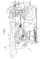
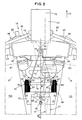
- This lightening device (64) comprises a group (68) of four traction springs (67) located in the vicinity of the vertical plane (70) directed in the direction of advance (12) at work and containing the center of the masses of the harvesting mechanism (19). It can also be seen that said lightening device (64) extends between the two groups (150, 151) of treatment members (21) and just behind two rotors (66) one extending near the another in the middle part of the cutter bar (48), symmetrically on either side of the vertical median plane (11 ′) of the harvesting mechanism (19) and each turning around an axis directed upwards, so that their respective directions of rotation diverge forward.
- This group (68) of four traction springs (67) is divided into two identical parts (69, 69 ′) each comprising two of the four springs (67). These parts (69, 69 ′) extend substantially symmetrically on either side of the vertical plane (70). In the example shown, said plane (70) is very close to the median plane (11 ′) of the harvesting mechanism (19). Moreover, in each part (69, 69 ′), the two springs (67) extend, taking into account the direction of advance (12) at work, one behind the other.
- a connecting member (71) connecting the respective upper end of these springs (67) to a common connecting piece (72) and the lower end respective said springs (67) with two yokes (73).
- Each yoke (73) is fixed to a respective part (69, 69 ′) of the group (68) of the four traction springs (67) and pivots on a trunnion (74) of geometric axis at least substantially horizontal and at least substantially orthogonal to the direction of advance (12) at work.
- This pin (74) is rigidly connected to the center of the cutter bar (48) by a coupling element (75) arranged at least substantially parallel to the two cutting planes generated by the cutting members (20), in the vicinity of said planes.
- the yokes (73) and the pin (74) thus constitute a joint (83) by means of which the lightening device (64) is linked to the harvesting mechanism (19).
- Two stiffening elements (76) extending forward and upward, are linked to their rear ends to the coupling element (75) by means of a joint (92) and at their front end to the cross member (93) by means of a joint (91).
- the articulation (92) is merged with the articulation (83) connecting the lightening device (64) to the harvesting mechanism (19), and that the articulation (91) is located above cutting members (20).
- the stiffening member thus formed forms a triangulation intended to increase the rigidity of the coupling element (75) also connecting together the two cutter bar parts (81, 82) constituting the cutter bar (48) .
- the common connecting piece (72) produced from a plate folded in a "U" shape, is linked by its central inner face to the connecting members (71) provided at the upper ends of the springs (67).
- This common connecting piece (72) thus defined comprises in its middle a circular hole surrounded by a spherical bearing face (90) whose concavity is directed downwards. Said circular hole is traversed by a screw (77) linked by means of a ball-type joint (78) to the console (45) of the chassis (14). To this end, the screw (77) has a spherical bearing face (87) collaborating with a spherical bearing face (88) of the console (45).
- This screw (77) extends at least substantially parallel to the springs (67) and comprises a nut (79) with a spherical bearing face (89) collaborating with the spherical bearing face (90) of the common connecting piece (72).
- the nut (79) is also equipped with a rectangular sheet (80), of length greater than the width of the common connecting piece (72). Therefore, the rotation of the nut (79) is prevented by the edges of the common connecting piece (72) during the rotation of the screw (77).
- the adjustment device (86) thus formed makes it possible, by turning the screw (77) in one direction or the other, to translate the common connecting piece (72) and to extend more or less the springs (67) so modulate the lightening of the harvesting mechanism (19).
- the ball joint connection between the nut (79) and the connecting piece common (72) allows by simple rotation of this common connecting piece (72) to remain substantially parallel to the coupling element (75). Thanks to this system, the two parts (69, 69 ′) of the group (68) of springs (67) retain at least substantially the same length.
- the telescopic transmission shaft with universal joints (41) which extends in a direction at least substantially parallel to the direction of advance ( 12) at work, passes between the two parts (69, 69 ′) of the group (68) of traction springs (67).
Landscapes
- Life Sciences & Earth Sciences (AREA)
- Environmental Sciences (AREA)
- Harvester Elements (AREA)
Applications Claiming Priority (2)
| Application Number | Priority Date | Filing Date | Title |
|---|---|---|---|
| FR8915686 | 1989-11-24 | ||
| FR8915686A FR2654897B1 (fr) | 1989-11-24 | 1989-11-24 | Faucheuse avec dispositif d'allegement perfectionne. |
Publications (2)
| Publication Number | Publication Date |
|---|---|
| EP0429383A1 true EP0429383A1 (de) | 1991-05-29 |
| EP0429383B1 EP0429383B1 (de) | 1995-03-01 |
Family
ID=9387900
Family Applications (1)
| Application Number | Title | Priority Date | Filing Date |
|---|---|---|---|
| EP90440108A Expired - Lifetime EP0429383B1 (de) | 1989-11-24 | 1990-11-22 | Mähmaschine mit verbesserter Entlastungsvorrichtung |
Country Status (9)
| Country | Link |
|---|---|
| US (1) | US5060462A (de) |
| EP (1) | EP0429383B1 (de) |
| JP (1) | JP2958352B2 (de) |
| AT (1) | ATE118964T1 (de) |
| CA (1) | CA2030728C (de) |
| DE (1) | DE69017363T2 (de) |
| DK (1) | DK0429383T3 (de) |
| ES (1) | ES2070301T3 (de) |
| FR (1) | FR2654897B1 (de) |
Cited By (5)
| Publication number | Priority date | Publication date | Assignee | Title |
|---|---|---|---|---|
| EP0806132A1 (de) * | 1996-05-09 | 1997-11-12 | Maasland N.V. | Landwirtschaftliche Maschine |
| FR2751166A1 (fr) * | 1996-07-22 | 1998-01-23 | Kuhn Sa | Machine agricole de recolte de vegetaux avec deux unites de conditionnement |
| FR2759531A1 (fr) * | 1997-02-14 | 1998-08-21 | Kuhn Sa | Machine agricole de coupe comportant un dispositif de suspension perfectionne du mecanisme de coupe |
| WO2011110940A1 (en) * | 2010-03-12 | 2011-09-15 | Forage Innovations B.V. | Automatically steered gearboxes for an implement with a pivoting tongue |
| FR2998130A1 (fr) * | 2012-11-21 | 2014-05-23 | Kuhn Sa | Faucheuse avec un arbre de transmission a coulissement ameliore |
Families Citing this family (52)
| Publication number | Priority date | Publication date | Assignee | Title |
|---|---|---|---|---|
| DK26790A (da) * | 1990-02-01 | 1991-08-02 | Taarup As Maskinfab | Skaarlaegger |
| FR2668881B1 (fr) * | 1990-11-12 | 1994-05-27 | Kuhn Sa | Machine agricole, en particulier faucheuse, s'adaptant aisement au relief du terrain et comportant un carter pivotant. |
| FR2668880B1 (fr) * | 1990-11-12 | 1995-06-30 | Kuhn Sa | Procede de transformation d'une machine de recolte pour l'amener d'une position de transport dans une position de travail, et machine de recolte. |
| DE4112154A1 (de) * | 1991-04-13 | 1992-10-15 | Moertl Schleppergeraetebau | Ueber eine zugdeichsel an einem schlepper anhaengbares maehwerk |
| US5272859A (en) * | 1992-04-14 | 1993-12-28 | Hay & Forage Industries | Mechanical drive center pivot mower conditioner |
| FR2696898B1 (fr) * | 1992-10-16 | 1994-12-09 | Kuhn Sa | Faucheuse avec un entraînement perfectionné des rouleaux de traitement. |
| US5327709A (en) * | 1993-03-12 | 1994-07-12 | Ford New Holland, Inc. | Adjustable header flotation mechanism |
| DK171261B1 (da) * | 1993-07-13 | 1996-08-19 | Freudendahl J Fab As | Slåmaskine omfattende to i forlængelse af hinanden liggende knivbjælker. |
| US5463852A (en) | 1994-04-28 | 1995-11-07 | Hay & Forage Industries | Wide cut harvester having rotary cutter bed |
| US5433064A (en) | 1994-04-28 | 1995-07-18 | Hay & Forage Industries | Rotary cutter bed harvester with non-auger conveying means for outboard cutters |
| FR2719189B1 (fr) * | 1994-04-29 | 1996-07-05 | Kuhn Sa | Faucheuse à dispositif de sécurité. |
| US5425224A (en) * | 1994-08-08 | 1995-06-20 | Downey; Sam | Mower deck carriage |
| FR2724689B1 (fr) * | 1994-09-16 | 1997-01-24 | Kuhn Sa | Mecanisme de verrouillage destine a equiper principalement une machine agricole |
| US5566535A (en) * | 1995-05-09 | 1996-10-22 | Hay & Forage Industries | Remote header angle adjustment mechanism for swing-tongue harvesters |
| FR2736505B1 (fr) * | 1995-07-13 | 1997-09-26 | Kuhn Sa | Faucheuse avec un dispositif d'andainage perfectionne |
| FR2743978B1 (fr) * | 1996-01-31 | 1998-04-17 | Kuhn Sa | Faucheuse avec organe de depose perfectionne |
| FR2747006B1 (fr) * | 1996-04-09 | 1998-05-29 | Kuhn Sa | Machine agricole avec moyen de liaison a un vehicule tracteur et carter de renvoi pivotants |
| US6003291A (en) * | 1996-04-09 | 1999-12-21 | Kuhn, S.A. | Agriculture machine |
| FR2749127B1 (fr) * | 1996-05-28 | 1998-08-07 | Kuhn Sa | Machine de coupe de vegetaux, destinee a etre attelee a un vehicule moteur, avec un dispositif de verrouillage du mecanisme de coupe |
| FR2759533B1 (fr) * | 1997-02-14 | 1999-04-23 | Kuhn Sa | Faucheuse comportant un dispositif empechant la transmission de tout ou partie des vibrations entre le mecanisme de coupe et la structure porteuse |
| FR2784003B1 (fr) | 1998-10-02 | 2000-12-29 | Kuhn Sa | Machine agricole comportant un timon pivotable et des organes de transmission comprenant un accouplement a joints universels |
| US6199355B1 (en) * | 1998-03-09 | 2001-03-13 | New Holland North America, Inc. | Control apparatus for rotatable gearbox on crop harvester |
| US6044633A (en) * | 1998-03-09 | 2000-04-04 | New Holland North America, Inc. | Control apparatus for rotatable gearbox on crop harvester |
| US6082085A (en) * | 1998-05-13 | 2000-07-04 | Agco Corporation | Foliage mowing implement having mechanical drive with main gearbox rotation |
| US6158201A (en) | 1998-09-15 | 2000-12-12 | Hay & Forage Industries | Rotary mower conditioner having improved cut crop flow |
| FR2786977B1 (fr) | 1998-12-14 | 2001-02-16 | Kuhn Sa | Faucheuse comportant un dispositif centralise de reglage de la force d'allegement exercee sur le mecanisme de recolte |
| FR2774853B1 (fr) | 1999-02-15 | 2001-02-16 | Kuhn Sa | Organe de coupe pour une machine de coupe notamment une faucheuse |
| FR2791224B1 (fr) | 1999-03-24 | 2001-05-25 | Kuhn Sa | Dispositif de coupe d'une machine de coupe, par exemple faucheuse comportant un dispositif d'entrainement du produit coupe |
| FR2792164B1 (fr) | 1999-04-16 | 2001-05-25 | Kuhn Sa | Dispositif de traitement de fourrage coupe et faucheuse utilisant un tel dispositif de traitement |
| FR2792161B1 (fr) | 1999-04-16 | 2001-05-25 | Kuhn Sa | Machine de coupe comportant un dispositif de coupe lie a un chassis au moyen d'un dispositif de liaison ameliore |
| FR2793379B1 (fr) | 1999-05-11 | 2001-07-06 | Kuhn Sa | Dispositif d'adaptation pour barre d'attelage de tracteur |
| FR2794206B1 (fr) | 1999-05-26 | 2001-07-06 | Kuhn Sa | Procede de montage/demontage et de reglage automatique de la tension d'un organe de transmission sans fin - machine agricole utilisant un tel procede |
| US6347502B1 (en) | 1999-06-16 | 2002-02-19 | Textron Inc. | Cutter assembly positioning mechanism and control for riding lawn mower |
| FR2823061B1 (fr) | 2001-04-06 | 2003-09-26 | Kuhn Sa | Machine de recolte avec un dispositif d'entrainement perfectionne |
| FR2823637A1 (fr) | 2001-04-18 | 2002-10-25 | Kuhn Sa | Faucheuse agricole comportant un mecanisme de regroupement d'andains |
| US6655118B1 (en) | 2002-08-13 | 2003-12-02 | Vermeer Manufacturing Company | Suspension system |
| US7334645B2 (en) * | 2003-05-07 | 2008-02-26 | Degelman Industries Ltd. | Articulated power transfer apparatus |
| US7520114B2 (en) * | 2006-01-03 | 2009-04-21 | The Toro Company | Mower with ground following cutting deck and weight transfer between deck and frame |
| FR2899430B1 (fr) * | 2006-04-11 | 2010-03-19 | Kuhn Sa | Rouleau conditionneur de faucheuse-conditionneuse, procede de fabrication d'un tel rouleau et faucheuse-conditionneuse equipee d'un tel rouleau |
| HU229564B1 (en) * | 2007-01-26 | 2014-02-28 | Optigep Kft | Harvest adapter equipped with stalk crusher for cereals, mainly for sunflower |
| US7475530B2 (en) | 2007-03-02 | 2009-01-13 | Textron Inc. | Articulating swing-out arm |
| US7658056B2 (en) * | 2007-10-30 | 2010-02-09 | Vermeer Manufacturing Co. | System for folding an agricultural machine with a floating work tool |
| US20090107100A1 (en) * | 2007-10-30 | 2009-04-30 | Bollinger Shane A | Cushioned swing cylinder for agricultural mower |
| US7596935B2 (en) * | 2007-10-30 | 2009-10-06 | Vermeer Manufacturing Company | Suspension system for a floating header on an agricultural implement |
| US7726109B2 (en) | 2007-10-30 | 2010-06-01 | Vermeer Manufacturing Co. | Four-bar linkage for suspending a header for an agricultural implement |
| FR2930864B1 (fr) | 2008-05-06 | 2012-11-09 | Kuhn Sa | Faucheuse avec un dispositif d'allegement perfectionne |
| US7726108B1 (en) | 2009-01-14 | 2010-06-01 | Agco Corporation | Wide cut rotary harvester having cut crop feeder mechanism |
| US8261521B2 (en) * | 2009-08-31 | 2012-09-11 | Vermeer Manufacturing Company | Self-leveling four-bar linkage for suspending a header of an agricultural implement |
| FR2966322B1 (fr) * | 2010-10-21 | 2012-11-02 | Kuhn Sa | Machine de recolte avec un dispositif d'allegement |
| CA2815427C (en) | 2012-04-26 | 2016-06-28 | Macdon Industries Ltd. | Pull-type crop harvesting machine transport system including a swath protection shield |
| US9131638B2 (en) * | 2013-04-29 | 2015-09-15 | Cnh Industrial America Llc | Intermediate lift cylinder lock for extra tall stubble biomass operation |
| CA3107840C (en) * | 2021-02-02 | 2023-06-27 | Todd Hofmann | Two way offset implement hitch |
Citations (8)
| Publication number | Priority date | Publication date | Assignee | Title |
|---|---|---|---|---|
| GB1583983A (en) * | 1977-04-05 | 1981-02-04 | Sperry Ltd | Harvesting machines |
| GB2053645A (en) * | 1977-11-21 | 1981-02-11 | Deere & Co | Mower-conditioner |
| US4719742A (en) * | 1984-04-12 | 1988-01-19 | Kuhn S.A. | Mowing machine |
| US4724661A (en) * | 1986-09-04 | 1988-02-16 | New Holland Inc. | Two piece crop harvesting header and flotation mechanism therefor |
| FR2614755A1 (fr) * | 1987-05-04 | 1988-11-10 | Kuhn Sa | Faucheuse munie d'un dispositif de reglage du piquage de l'organe de coupe |
| NL8701155A (nl) * | 1987-05-14 | 1988-12-01 | Lely Nv C Van Der | Kneusinrichting en maaiinrichting voorzien van kneusinrichting. |
| EP0382666A1 (de) * | 1989-02-07 | 1990-08-16 | Kuhn S.A. | Mähmaschine mit selbstauslösender Sicherheitsvorrichtung |
| EP0406961A1 (de) * | 1989-07-06 | 1991-01-09 | C. van der Lely N.V. | Mähmaschine |
Family Cites Families (4)
| Publication number | Priority date | Publication date | Assignee | Title |
|---|---|---|---|---|
| US3783594A (en) * | 1972-09-18 | 1974-01-08 | Int Harvester Co | Harvester platform suspension and linkage system |
| US3808781A (en) * | 1972-12-08 | 1974-05-07 | Deere & Co | Harvesting platform suspension system |
| FR2608362B1 (fr) * | 1986-12-22 | 1990-10-12 | Kuhn Sa | Faucheuse avec dispositif de suspension des groupes de fauche perfectionne |
| FR2627942B1 (fr) * | 1988-03-04 | 1990-08-10 | Kuhn Sa | Perfectionnement aux machines agricoles pour la recolte |
-
1989
- 1989-11-24 FR FR8915686A patent/FR2654897B1/fr not_active Expired - Fee Related
-
1990
- 1990-11-22 EP EP90440108A patent/EP0429383B1/de not_active Expired - Lifetime
- 1990-11-22 ES ES90440108T patent/ES2070301T3/es not_active Expired - Lifetime
- 1990-11-22 DE DE69017363T patent/DE69017363T2/de not_active Expired - Fee Related
- 1990-11-22 DK DK90440108.0T patent/DK0429383T3/da active
- 1990-11-22 AT AT90440108T patent/ATE118964T1/de not_active IP Right Cessation
- 1990-11-23 CA CA002030728A patent/CA2030728C/fr not_active Expired - Lifetime
- 1990-11-26 US US07/617,581 patent/US5060462A/en not_active Expired - Lifetime
- 1990-11-26 JP JP2322220A patent/JP2958352B2/ja not_active Expired - Fee Related
Patent Citations (8)
| Publication number | Priority date | Publication date | Assignee | Title |
|---|---|---|---|---|
| GB1583983A (en) * | 1977-04-05 | 1981-02-04 | Sperry Ltd | Harvesting machines |
| GB2053645A (en) * | 1977-11-21 | 1981-02-11 | Deere & Co | Mower-conditioner |
| US4719742A (en) * | 1984-04-12 | 1988-01-19 | Kuhn S.A. | Mowing machine |
| US4724661A (en) * | 1986-09-04 | 1988-02-16 | New Holland Inc. | Two piece crop harvesting header and flotation mechanism therefor |
| FR2614755A1 (fr) * | 1987-05-04 | 1988-11-10 | Kuhn Sa | Faucheuse munie d'un dispositif de reglage du piquage de l'organe de coupe |
| NL8701155A (nl) * | 1987-05-14 | 1988-12-01 | Lely Nv C Van Der | Kneusinrichting en maaiinrichting voorzien van kneusinrichting. |
| EP0382666A1 (de) * | 1989-02-07 | 1990-08-16 | Kuhn S.A. | Mähmaschine mit selbstauslösender Sicherheitsvorrichtung |
| EP0406961A1 (de) * | 1989-07-06 | 1991-01-09 | C. van der Lely N.V. | Mähmaschine |
Cited By (10)
| Publication number | Priority date | Publication date | Assignee | Title |
|---|---|---|---|---|
| EP0806132A1 (de) * | 1996-05-09 | 1997-11-12 | Maasland N.V. | Landwirtschaftliche Maschine |
| FR2751166A1 (fr) * | 1996-07-22 | 1998-01-23 | Kuhn Sa | Machine agricole de recolte de vegetaux avec deux unites de conditionnement |
| EP0821870A1 (de) * | 1996-07-22 | 1998-02-04 | Kuhn S.A. | Mähmaschine mit Aufbereiter |
| US5992133A (en) * | 1996-07-22 | 1999-11-30 | Kuhn S.A. | Agricultural machine for harvesting plant matter, with two conditioning units |
| FR2759531A1 (fr) * | 1997-02-14 | 1998-08-21 | Kuhn Sa | Machine agricole de coupe comportant un dispositif de suspension perfectionne du mecanisme de coupe |
| EP0861581A1 (de) * | 1997-02-14 | 1998-09-02 | Kuhn S.A. | Landwirtschaftliche Mähmaschine mit verbesserter Aufhängungsvorrichtung des Mähwerks |
| US6055800A (en) * | 1997-02-14 | 2000-05-02 | Kuhn S.A. | Agricultural cutting machine comprising an improved suspension device for the cutting mechanism |
| WO2011110940A1 (en) * | 2010-03-12 | 2011-09-15 | Forage Innovations B.V. | Automatically steered gearboxes for an implement with a pivoting tongue |
| US8256198B2 (en) | 2010-03-12 | 2012-09-04 | Forage Innovations B.V. | Automatically steered gearboxes for an implement with a pivoting tongue |
| FR2998130A1 (fr) * | 2012-11-21 | 2014-05-23 | Kuhn Sa | Faucheuse avec un arbre de transmission a coulissement ameliore |
Also Published As
| Publication number | Publication date |
|---|---|
| FR2654897B1 (fr) | 1992-03-20 |
| ES2070301T3 (es) | 1995-06-01 |
| EP0429383B1 (de) | 1995-03-01 |
| JP2958352B2 (ja) | 1999-10-06 |
| CA2030728C (fr) | 2001-01-16 |
| US5060462A (en) | 1991-10-29 |
| CA2030728A1 (fr) | 1991-05-25 |
| ATE118964T1 (de) | 1995-03-15 |
| JPH03183413A (ja) | 1991-08-09 |
| DK0429383T3 (da) | 1995-07-10 |
| FR2654897A1 (fr) | 1991-05-31 |
| DE69017363T2 (de) | 1995-10-19 |
| DE69017363D1 (de) | 1995-04-06 |
Similar Documents
| Publication | Publication Date | Title |
|---|---|---|
| EP0429383B1 (de) | Mähmaschine mit verbesserter Entlastungsvorrichtung | |
| EP0429381B1 (de) | Landmaschine mit verbesserter Aufhängungsvorrichtung der Arbeitswerkzeugeeinheit | |
| EP0297012B1 (de) | Mähmaschine | |
| EP0429382B1 (de) | Mähmaschine mit einer sich quer zur Fahrtrichtung erstreckenden Arbeitswerkzeugeeinheit | |
| CA2226656C (fr) | Machine agricole de coupe perfectionnee | |
| EP0821870B1 (de) | Mähmaschine mit Aufbereiter | |
| FR2660518A1 (fr) | Machine agricole avec dispositif de detection de la position intermediaire du moyen de liaison. | |
| EP0461056B1 (de) | Landwirtschaftliche Maschine versehen mit zwei Elementen, die mittels eines geschützten Gelenkes miteinander verbunden sind | |
| EP0242311A1 (de) | Rotations-Mähwerk mit Mähbalken und Trägerstruktur | |
| FR2760934A1 (fr) | Dispositif d'orientation de la boite a engrenages d'une moissonneuse conditionneuse | |
| FR2806871A1 (fr) | Machine de fenaison comportant au moins une roue rateleuse articulee sur un bras porteur | |
| EP0680688B1 (de) | Heuwerbungsmaschine, insbesondere ein Schwader für Futter | |
| EP1434476A1 (de) | Landmaschine, insbesondere kreiselmäher, mit verbesserter häckselvorrichtung | |
| FR2534442A1 (en) | Self-propelled lawnmower | |
| EP0486415B1 (de) | Mähmaschine mit unabhängigem Rahmen, der Aufhängungs- und Erleichterungsvorrichtungen aufweisst | |
| EP0914766B1 (de) | Heuwerbungsmachine | |
| EP0733302B1 (de) | Heuwerbungsmaschine | |
| EP3973754B1 (de) | Drehpflug vom typ aufsattelpflug mit wagen oder einzelrad | |
| EP0779022A1 (de) | Heuwerbungsmaschine | |
| EP0501899B1 (de) | Kreiselegge mit mehreren starr mit einer verbesserten Anbauvorrichtung verbundenen Tragbalken | |
| FR2644029A1 (fr) | Dispositif d'attelage pivotant pour outil agricole de grande largeur | |
| FR2851120A1 (fr) | Charrue reversible semi-porte | |
| FR2543905A1 (fr) | Tracteur ou vehicule dont les roues directrices sont egalement motrices | |
| FR2881023A1 (fr) | Rotor d'andaineur | |
| BE434571A (de) |
Legal Events
| Date | Code | Title | Description |
|---|---|---|---|
| PUAI | Public reference made under article 153(3) epc to a published international application that has entered the european phase |
Free format text: ORIGINAL CODE: 0009012 |
|
| AK | Designated contracting states |
Kind code of ref document: A1 Designated state(s): AT BE DE DK ES FR GB IT NL SE |
|
| 17P | Request for examination filed |
Effective date: 19911009 |
|
| 17Q | First examination report despatched |
Effective date: 19921013 |
|
| GRAA | (expected) grant |
Free format text: ORIGINAL CODE: 0009210 |
|
| AK | Designated contracting states |
Kind code of ref document: B1 Designated state(s): AT BE DE DK ES FR GB IT NL SE |
|
| REF | Corresponds to: |
Ref document number: 118964 Country of ref document: AT Date of ref document: 19950315 Kind code of ref document: T |
|
| REF | Corresponds to: |
Ref document number: 69017363 Country of ref document: DE Date of ref document: 19950406 |
|
| ITF | It: translation for a ep patent filed | ||
| PG25 | Lapsed in a contracting state [announced via postgrant information from national office to epo] |
Ref country code: SE Effective date: 19950601 |
|
| REG | Reference to a national code |
Ref country code: ES Ref legal event code: FG2A Ref document number: 2070301 Country of ref document: ES Kind code of ref document: T3 |
|
| GBT | Gb: translation of ep patent filed (gb section 77(6)(a)/1977) |
Effective date: 19950605 |
|
| REG | Reference to a national code |
Ref country code: DK Ref legal event code: T3 |
|
| PG25 | Lapsed in a contracting state [announced via postgrant information from national office to epo] |
Ref country code: BE Effective date: 19951130 |
|
| PLBE | No opposition filed within time limit |
Free format text: ORIGINAL CODE: 0009261 |
|
| STAA | Information on the status of an ep patent application or granted ep patent |
Free format text: STATUS: NO OPPOSITION FILED WITHIN TIME LIMIT |
|
| 26N | No opposition filed | ||
| BERE | Be: lapsed |
Owner name: S.A. KUHN Effective date: 19951130 |
|
| REG | Reference to a national code |
Ref country code: GB Ref legal event code: IF02 |
|
| PGFP | Annual fee paid to national office [announced via postgrant information from national office to epo] |
Ref country code: DK Payment date: 20081023 Year of fee payment: 19 Ref country code: NL Payment date: 20081028 Year of fee payment: 19 Ref country code: DE Payment date: 20081126 Year of fee payment: 19 |
|
| PGFP | Annual fee paid to national office [announced via postgrant information from national office to epo] |
Ref country code: ES Payment date: 20081107 Year of fee payment: 19 Ref country code: AT Payment date: 20081023 Year of fee payment: 19 |
|
| PGFP | Annual fee paid to national office [announced via postgrant information from national office to epo] |
Ref country code: IT Payment date: 20081117 Year of fee payment: 19 |
|
| PGFP | Annual fee paid to national office [announced via postgrant information from national office to epo] |
Ref country code: FR Payment date: 20081126 Year of fee payment: 19 |
|
| PGFP | Annual fee paid to national office [announced via postgrant information from national office to epo] |
Ref country code: GB Payment date: 20081029 Year of fee payment: 19 |
|
| REG | Reference to a national code |
Ref country code: NL Ref legal event code: V1 Effective date: 20100601 |
|
| REG | Reference to a national code |
Ref country code: DK Ref legal event code: EBP |
|
| GBPC | Gb: european patent ceased through non-payment of renewal fee |
Effective date: 20091122 |
|
| REG | Reference to a national code |
Ref country code: FR Ref legal event code: ST Effective date: 20100730 |
|
| PG25 | Lapsed in a contracting state [announced via postgrant information from national office to epo] |
Ref country code: AT Free format text: LAPSE BECAUSE OF NON-PAYMENT OF DUE FEES Effective date: 20091122 |
|
| PG25 | Lapsed in a contracting state [announced via postgrant information from national office to epo] |
Ref country code: FR Free format text: LAPSE BECAUSE OF NON-PAYMENT OF DUE FEES Effective date: 20091130 Ref country code: NL Free format text: LAPSE BECAUSE OF NON-PAYMENT OF DUE FEES Effective date: 20100601 |
|
| PG25 | Lapsed in a contracting state [announced via postgrant information from national office to epo] |
Ref country code: DE Free format text: LAPSE BECAUSE OF NON-PAYMENT OF DUE FEES Effective date: 20100601 |
|
| PG25 | Lapsed in a contracting state [announced via postgrant information from national office to epo] |
Ref country code: GB Free format text: LAPSE BECAUSE OF NON-PAYMENT OF DUE FEES Effective date: 20091122 |
|
| PG25 | Lapsed in a contracting state [announced via postgrant information from national office to epo] |
Ref country code: DK Free format text: LAPSE BECAUSE OF NON-PAYMENT OF DUE FEES Effective date: 20091130 |
|
| PG25 | Lapsed in a contracting state [announced via postgrant information from national office to epo] |
Ref country code: IT Free format text: LAPSE BECAUSE OF NON-PAYMENT OF DUE FEES Effective date: 20091122 |
|
| REG | Reference to a national code |
Ref country code: ES Ref legal event code: FD2A Effective date: 20110408 |
|
| PG25 | Lapsed in a contracting state [announced via postgrant information from national office to epo] |
Ref country code: ES Free format text: LAPSE BECAUSE OF NON-PAYMENT OF DUE FEES Effective date: 20110328 |
|
| PG25 | Lapsed in a contracting state [announced via postgrant information from national office to epo] |
Ref country code: ES Free format text: LAPSE BECAUSE OF NON-PAYMENT OF DUE FEES Effective date: 20091123 |