EP0429491B1 - Verfahren und HILFSMITTEL ZUM FÜGEN VON KONTAKTEN IN STECKERGEHÄUSE - Google Patents
Verfahren und HILFSMITTEL ZUM FÜGEN VON KONTAKTEN IN STECKERGEHÄUSE Download PDFInfo
- Publication number
- EP0429491B1 EP0429491B1 EP89908961A EP89908961A EP0429491B1 EP 0429491 B1 EP0429491 B1 EP 0429491B1 EP 89908961 A EP89908961 A EP 89908961A EP 89908961 A EP89908961 A EP 89908961A EP 0429491 B1 EP0429491 B1 EP 0429491B1
- Authority
- EP
- European Patent Office
- Prior art keywords
- pole
- tip
- contacts
- open
- chambers
- Prior art date
- Legal status (The legal status is an assumption and is not a legal conclusion. Google has not performed a legal analysis and makes no representation as to the accuracy of the status listed.)
- Expired - Lifetime
Links
- 238000000034 method Methods 0.000 title claims description 7
- 238000003780 insertion Methods 0.000 claims abstract description 7
- 230000037431 insertion Effects 0.000 claims abstract description 7
- 238000003892 spreading Methods 0.000 claims description 7
- 238000002788 crimping Methods 0.000 claims 1
- 239000011796 hollow space material Substances 0.000 claims 1
- 238000006073 displacement reaction Methods 0.000 description 6
- 238000005304 joining Methods 0.000 description 6
- 238000004519 manufacturing process Methods 0.000 description 3
- 238000011161 development Methods 0.000 description 2
- 230000018109 developmental process Effects 0.000 description 2
- 238000013461 design Methods 0.000 description 1
- 238000012986 modification Methods 0.000 description 1
- 230000004048 modification Effects 0.000 description 1
Images
Classifications
-
- H—ELECTRICITY
- H01—ELECTRIC ELEMENTS
- H01R—ELECTRICALLY-CONDUCTIVE CONNECTIONS; STRUCTURAL ASSOCIATIONS OF A PLURALITY OF MUTUALLY-INSULATED ELECTRICAL CONNECTING ELEMENTS; COUPLING DEVICES; CURRENT COLLECTORS
- H01R43/00—Apparatus or processes specially adapted for manufacturing, assembling, maintaining, or repairing of line connectors or current collectors or for joining electric conductors
- H01R43/20—Apparatus or processes specially adapted for manufacturing, assembling, maintaining, or repairing of line connectors or current collectors or for joining electric conductors for assembling or disassembling contact members with insulating base, case or sleeve
Definitions
- the present invention relates to a method and a device for joining contacts in a plug housing with a plurality of pole chambers, the contacts being inserted at least partially in succession into the individual pole chambers.
- a corresponding device and such a method are known from FR-A-2,607,653.
- This document generally shows a method and an apparatus for the automatic attachment of contacts and cables to plugs having a plurality of pole chambers, but this document provides details of the insertion of the contacts into the pole chambers, in particular in an arbitrary order, for example that Removal of cables protruding from the pole chambers would not be necessary.
- EP-A-299.897 which is a document according to Article 54 (3) EPC, a method and a device are known in which the tip of a tubular element, through which contacts are brought to the pole chambers, by advancing a tube or of a plug element is spread apart and possibly pushes aside in front of the pole chamber or in front of a plug contact.
- the parts of which the tip is obviously made are pivoted about their starting point on a pipe or the like.
- the tip is smooth on the outside and has no special structure.
- Such “multiple plugs” typically have up to 30 or more individual poles.
- an industrial engine or A corresponding multi-axis positioning device which guides different tools, such as laying tools, joining tools, etc. one after the other, thus laying the individual cables of the cable harness and connecting them to the poles in the pole chambers or inserting poles already attached to the cables and in particular crimp contacts into the pole chambers .
- the invention is therefore based on the object of increasing the manufacturing reliability when charging multiple plugs with cables or contacts.
- an aid is created for joining contacts and in particular crimp contacts in a plug housing with a plurality of pole chambers.
- This tool has an element that is positioned in front of the pole chamber to be equipped.
- This element has a tip, the diameter of which when positioned is smaller than the typical dimensions of the pole chamber. This makes it possible to position the element, which is also referred to as a displacement element due to its function described below, in front of the pole chamber to be equipped, so that there is no cable protruding from adjacent pole chambers between the pole chamber and the displacement element.
- the tip (claim 7) of the displacement element which is divided into two or more parts, is spread out in such a way that the dimensions of its tip are greater than are the dimensions of the pole chamber.
- the aid according to the invention can of course also be used in the manual assembly of cable harnesses. However, it is particularly advantageous in the automated production of cable harnesses.
- the spreadable tip can be spread, for example, by a special "spreading mechanism” or by the contact to be joined (claims 5 and 6, respectively).
- the aid according to the invention is particularly advantageous when equipping plug housings with so-called crimp contacts (claim 8).
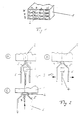
- Fig. 1 shows an example of a multiple connector to be fitted with a connector 1 with a three-row (x to z) and a four-column (a to d) pole arrangement, i.e. with twelve pole chambers 2.
- FIG. 2a shows how an aid 3 according to the invention is positioned in front of a pole chamber 2 of the connector shown in FIG. 1.
- the aid 3 has a tip 4, an adjoining section 5 with a frustoconical inner and outer contour and a cylindrical section 6. Furthermore, the aid 3 is divided into two or four (or more) parts, so that it can be spread with a mechanism, not shown.
- the tip 4 in the non-spread state are smaller than the dimensions of the pole chamber 2, the tip 4 easily pushes aside in front of the pole chamber 2 any cables that are in front of the pole chamber and that belong to neighboring pole chambers.
- Figure 2b shows that before the insertion of a contact 7, the aid 3 according to the invention, which - as already explained - consists of two or more, preferably four parts, is spread apart.
- This relative movement "displaces" cables belonging to the adjacent pole chamber, i.e. pushed aside. After the described relative movement of the device, the joining space for the crimp contact is free, so that, as shown in FIG. 2c, it can be inserted into the pole chamber 2 without any problems.
- the cylindrical section 6 serves on the one hand to hold the aid 3 according to the invention, for example with a gripper (not shown in more detail), and on the other hand it serves to insert and then guide the contact 7 at a distance at which cables "protruding from adjacent pole chambers" no longer "interfere.
- the spreading movement can be caused not only by specially designed spreading elements, but also by the crimp contact 7 itself.
- the object of the invention is used to feed multiple plugs with cables and contacts using industrial robots.
Landscapes
- Engineering & Computer Science (AREA)
- Manufacturing & Machinery (AREA)
- Manufacturing Of Electrical Connectors (AREA)
- Coupling Device And Connection With Printed Circuit (AREA)
- Connector Housings Or Holding Contact Members (AREA)
- Manipulator (AREA)
- Details Of Connecting Devices For Male And Female Coupling (AREA)
- Multi-Conductor Connections (AREA)
Description
- Die vorliegende Erfindung betrifft ein Verfahren und eine Vorrichtung zum Fügen von Kontakten in Steckergehäuse mit einer Mehrzahl von Polkammern, wobei die Kontakte mindestens teilweise nacheinander in die einzelnen Polkammern eingesetzt werden.
- Eine entsprechende Vorrichtung und ein solches Verfahren sind aus der FR-A-2,607,653 bekannt. Diese Druckschrift zeigt ganz allgemein ein Verfahren und eine Vorrichtung für die automatische Anbringung von Kontakten und Kabeln an Steckern, die eine Vielzahl von Polkammern aufweisen, jedoch sind dieser Druckschrift Einzelheiten des Einbringens der Kontakte in die Polkammern, insbesondere in einer willkürlichen Reihenfolge, die beispielsweise das Beseiteschleben von aus den Polkammern herausragenden Kabeln erforderlich machen würde, nicht zu entnehmen.
- Aus der EP-A-299.897, die ein Dokument nach Artikel 54(3) EPÜ ist, sind ein Verfahren und eine Vorrichtung bekannt, bei welchen die Spitze eines rohrförmigen Elementes, durch welches Kontakte an die Polkammern herangeführt werden, durch Vorschieben eines Rohres oder eines Steckerelementes auseinandergespreitzt wird und dabei eventuell vor der Polkammer bzw. vor einem Steckkontakt liegende Kabel beiseite drängt.
- Dabei werden die Teile, aus welchen die Spitze offensichtlich besteht, um ihren Ansatzpunkt an einem Rohr oder dergleichen verschwenkt. An der Außenseite ist die Spitze glatt und ohne besondere Struktur ausgebildet.
- Um eine höhere Informationsdichte mit Kabelbäumen zu erreichen, werden immer mehr Stecker mit einer Vielzahl von Polkammern verwendet, bei denen die einzelnen Pole in Zeilen bzw. Spalten neben- und übereinander angeordnet sind.
- Derartige "Vielfachstecker" weisen typischerweise bis zu 30 und mehr einzelne Pole auf. Andererseits werden seit einiger Zeit verstärkt Anstrengungen unternommen, Kabelbäume automatisiert herzustellen.
- Hierzu wird in der Regel ein Industriemotorbzw. eine entsprechende mehrachsige Positioniereinrichtung verwendet, die nacheinander verschiedene Werkzeuge, wie beispielsweise Verlegewerkzeuge, Fügewerkzeuge etc. führt und so die einzelnen Kabel des Kabelbaums verlegt und mit den Polen in den Polkammern verbindet bzw. bereits an den Kabeln angebrachte Pole und insbesondere Crimpkontakte in die Polkammern einsteckt.
- Sollen nun Kabel bzw. an den einzelnen Kabel bereits angebrachte Stecker in die einleitend genannten "Vielfachstecker" gefügt werden, so ergeben sich in der Regel dann Probleme, wenn die größte Zahl von Polkammern bereits mit Steckern bzw. Kabeln versehen ist: Die Zugänglichkeit der restlichen Polkammern wird durch die bereits montierten Kabel behindert. Erschwerend kommt hinzu, daß es nicht möglich ist, bei allen Steckern die Polkammern in einer fortlaufenden Reihe zu beschicken, so daß es unter Umständen erforderlich ist, eine Polkammer zu beschicken, bei der die umliegenden Polkammern bereits mit Kabeln versehen sind
- Deshalb ergeben sich insbesondere bei der automatisierten Fertigung von Kabelbäumen Probleme durch Kollision zwischen den zu fügenden Kontakten und den bereits montierten und aus dem Steckergehäuse hervorstehenden Kabeln.
- Der Erfindung liegt deshalb die Aufgabe zugrunde, die Fertigungssicherheit bei der Beschickung von Vielfachsteckern mit Kabeln bzw. Kontakten zu erhöhen.
- Eine erfindungsgemäße Lösung dieser Aufgabe ist mit ihren Weiterbildungen in den Patentansprüchen gekennzeichnet.
- Unter Berücksichtigung der EP-A-299.897 ist für die Vertragsstaaten Österreich und Frankreich ein anderer Satz von Patentansprüchen formuliert worden als für die übrigen Vertragsstaaten.
- Erfindungsgemäß wird ein Hilfsmittel zum Fügen von Kontakten und insbesondere von Crimpkontakten in Steckergehäuse mit einer Mehrzahl von Polkammern geschaffen. Dieses Hilfsmittel weist ein Element auf, das vor der zu bestückenden Polkammer positioniert wird. Dieses Element hat eine Spitze, deren Durchmesser bei der Positionierung kleiner als typische Abmessungen der Polkammer ist. Hierdurch ist es möglich, das Element, das aufgrund seiner im folgenden beschriebenen Funktion auch als Verdrängerelement bezeichnet wird, sovor der zu bestückenden Polkammerzu positionieren, daß sich zwischen der Polkammer und dem Verdrängerelement kein aus benachbarten Polkammern herausragendes Kabel befindet.
- Nach der Positionierung vor der zu bestückenden Polkammer und vor dem Einsetzen des Kontakts bzw. eines an einem bereits eingesetzten Kontakt zu befestigenden Kabels wird die in zwei oder mehr Teile geteilte Spitze (Anspruch 7) des Verdrängerelements derart aufgespreizt, daß die Abmessungen ihrer Spitze größer als die Abmessungen der Polkammer sind. Hierdurch werden in der Fügelinie des zu fügenden Teils liegende Kabel, die zu benachbarten Polkammern gehören, zur Seite geschoben
- Weiterbildungen der Erfindung sind in den Unteransprüchen angegeben.
- Durch die im Anspruch 2 angegebene Ausbildung des sich an die aufspreizbare Spitze anschließenden Teils wird eine zusätzliche Trichterwirkung für das zu fügende Teil und ein vorteilhafter "Verdrängereffekt" auf störende kabel erzielt.
- Das erfindungsgemäße Hilfsmittel kann selbstverständlich auch bei der manuellen Montage von Kabelbäumen verwendet werden. Besonders vorteilhaft ist es jedoch bei der automatisierten Fertigung von Kabelbäumen.
- Hierbei ist es entweder möglich, das erfindungsgemäße Hilfsmittel mittels eines Greifers, der bspw. an einem Industrieroboter angebracht ist, vor der jeweils zu beschickenden Polkammer zu positionieren (Anspruch 3), oder das erfindungsgemäße Hilfsmittel direkt an einem Fügewerkzeug für Kabel und/oder Kontakte anzubringen (Anspruch 4).
- Das Aufspreizen der aufspreizbaren Spitze kann bspw. durch einen speziellen "Spreizmechanismus" oder durch den zu fügenden Kontakt erfolgen (Ansprüche 5 bzw. 6).
- In jenem Falle ist das erfindungsmäße Hilfsmittel besonders vorteilhaft bei der Bestückung von Steckergehäusen mit sog. Crimpkontakten (Anspruch 8).
- Die Erfindung wird nachstehend anhand eines Ausführungsbeispiels unter Bezugnahme auf die Zeichnung näher beschrieben, in der zeigen
- Fig. 1 ein Beispiel für einen zu bestükkenden Vielfachstecker, und
- Fig. 2a bis 2c die Bestückung einer Polkammer mit einem erfindungsgemäßen Hilfsmittel.
- Fig. 1 zeigt als Beispiel für einen zu bestückenden Vielfachstecker einen Stecker 1 mit einer dreireihigen (x bis z) und einervierspaltigen (a bis d) Polanordnung d.h. mit zwölf Polkammern 2.
- Fig 2a zeigt, wie ein erfindungsgemäßes Hilfsmittel 3 vor einer Polkammer 2 des in Fig. 1 dargestellten Stekkers positioniert ist. Das Hilfsmittel 3 weist eine Spitze 4, einen sich daran anschließenden Abschnitt 5 mit kegelstumpfförmiger Innen- und Außenkontur sowie einen zylindrischen Abschnitt 6 auf. Ferner ist das Hilfsmittel 3 in zwei oder vier (oder auch mehr) Teile geteilt, so daß es mit einem nicht dargestellten Mechanismus aufgespreizt werden Kann.
- Da die Abmessungen der Spitze 4 im nicht aufgespreizten Zustand kleiner als die Abmessungen der Polkammer 2 sind, schiebt die Spitze 4 bei der Positionierung vor der Polkammer 2 problemlos ggf. vor der Polkammer liegende Kabel, die zu benachbarten Polkammern gehören, zur Seite.
- Figur 2b zeigt, daß vor dem Einsetzen eines Kontakts 7 das erfindungsgemäße Hilfsmittel 3, das hierzu - wie bereits erläutert - aus zwei oder mehr, vorzugsweise vier Teilen besteht, aufgespreizt wird.
- Durch diese Relativbewegung werden zu benachbarten Polkammer gehörende Kabel "verdrängt", d.h. zur Seite geschoben. Nach der beschriebenen Relativbewegung der Vorrichtung ist der Fügeraum für den Crimpkontaktfrei, so daß erwie in Fig. 2c gezeigt, problemlos in die Polkammer 2 eingeschoben werden kann.
- Durch die bei dem gezeigten Ausführungsbeispiel an die eigentliche Spitze anschließenden Flanken 5, die zu einer kegelstumpfförmigen Innen- und Außenkontur führen, wird zu einem eine vorteilhafte Trichterwirkung für den kontakt und zum anderen eine zusätzliche Verdrängerwirkung beim Spreizen des Verdrängerelements erzielt.
- Der zylindrische Abschnitt 6 dient einerseits zum Halten des erfindungsgemäßen Hilfsmittels 3 beispielsweise mit einem nicht näher dargestellten Greifer, zum anderen dient er zum Einführen und anschließenden Führen des kontakts 7 in einer Entfernung, in der aus benachbarten Polkammern herausragende Kabeln "nicht mehr" stören.
- Vorstehend ist die Erfindung anhand eines Ausführungsbeispiels ohne Beschränkung des allgemeinen Erfindungsgedankens beschrieben worden, innerhalb dessen selbstverständlich die verschiedensten Modifikationen möglich sind:
- So ist es möglich, daß erfindungsgemäße Hilfsmittel mittels eines Greifers vor der Polkammer zu positionieren, oder dieses direkt an einem Bestückungswerkzeug anzubauen.
- Die Spreizbewegung kann nicht nur durch speziell gestaltete Spreizelemente, sondern auch durch den Crimpkontakt 7 selbst hervorgerufen werden.
- Der erfindungsgemäße Gegenstand dient zur Beschickung von Vielfachsteckern mit Kabeln und Kontakten mit Hilfe von Industrierobotern.
Claims (10)
Applications Claiming Priority (3)
| Application Number | Priority Date | Filing Date | Title |
|---|---|---|---|
| DE3826990A DE3826990A1 (de) | 1988-08-09 | 1988-08-09 | Hilfsmittel zum fuegen von kontakten in steckergehaeuse |
| DE3826990 | 1988-08-09 | ||
| PCT/DE1989/000526 WO1990001818A2 (de) | 1988-08-09 | 1989-08-09 | Hilfsmittel zum fügen von kontakten in steckergehäuse |
Publications (2)
| Publication Number | Publication Date |
|---|---|
| EP0429491A1 EP0429491A1 (de) | 1991-06-05 |
| EP0429491B1 true EP0429491B1 (de) | 1996-04-03 |
Family
ID=6360507
Family Applications (1)
| Application Number | Title | Priority Date | Filing Date |
|---|---|---|---|
| EP89908961A Expired - Lifetime EP0429491B1 (de) | 1988-08-09 | 1989-08-09 | Verfahren und HILFSMITTEL ZUM FÜGEN VON KONTAKTEN IN STECKERGEHÄUSE |
Country Status (4)
| Country | Link |
|---|---|
| EP (1) | EP0429491B1 (de) |
| AT (1) | ATE136405T1 (de) |
| DE (2) | DE3826990A1 (de) |
| WO (1) | WO1990001818A2 (de) |
Families Citing this family (3)
| Publication number | Priority date | Publication date | Assignee | Title |
|---|---|---|---|---|
| DE4010349A1 (de) * | 1990-03-28 | 1991-10-02 | Siemens Ag | Steckmodul fuer eine kabelkonfektioniereinrichtung |
| DE9105277U1 (de) * | 1991-04-29 | 1992-08-27 | Grote & Hartmann Gmbh & Co Kg, 42369 Wuppertal | Elektrisches Steckergehäuse mit Findungseinrichtung für ein in eine Kontaktkammer des Steckergehäuses zu steckendes elektrisches Kontaktelement |
| US5459924A (en) * | 1993-01-11 | 1995-10-24 | Yazaki Corporation | Method of inserting terminal with wire and apparatus therefor |
Family Cites Families (6)
| Publication number | Priority date | Publication date | Assignee | Title |
|---|---|---|---|---|
| US3636612A (en) * | 1970-04-09 | 1972-01-25 | Lorain Prod Corp | Tool for staking a terminal pin to a terminal lug |
| US3676912A (en) * | 1971-03-31 | 1972-07-18 | Itt | Electrical contact insertion-extraction tool |
| GB1585201A (en) * | 1977-01-25 | 1981-02-25 | Amp Inc | Wire feed and contact insertion apparatus |
| FR2607653B1 (fr) * | 1986-11-28 | 1989-03-31 | Ricard Claude | Procedes et dispositifs pour connecter automatiquement sur un ensemble de composants electriques des pieces de connexion serties sur des fils conducteurs et palettes destinees a cet usage |
| FR2618286B1 (fr) * | 1987-07-17 | 1989-12-15 | Ricard Claude | Procedes et dispositifs pour connecter mecaniquement sur chaque borne ou dans chaque alveole de composants electriques, une piece de connexion faisant partie d'un lot de fils conducteurs equipes de telles pieces. |
| FR2622743B1 (fr) * | 1987-10-28 | 1990-01-19 | Labinal | Dispositif d'enfichage de contacts dans un boitier de connecteur |
-
1988
- 1988-08-09 DE DE3826990A patent/DE3826990A1/de active Granted
-
1989
- 1989-08-09 EP EP89908961A patent/EP0429491B1/de not_active Expired - Lifetime
- 1989-08-09 WO PCT/DE1989/000526 patent/WO1990001818A2/de not_active Ceased
- 1989-08-09 AT AT89908961T patent/ATE136405T1/de not_active IP Right Cessation
- 1989-08-09 DE DE58909641T patent/DE58909641D1/de not_active Expired - Fee Related
Also Published As
| Publication number | Publication date |
|---|---|
| DE3826990C2 (de) | 1990-05-17 |
| DE58909641D1 (de) | 1996-05-09 |
| ATE136405T1 (de) | 1996-04-15 |
| WO1990001818A2 (de) | 1990-02-22 |
| EP0429491A1 (de) | 1991-06-05 |
| WO1990001818A3 (de) | 1990-05-03 |
| DE3826990A1 (de) | 1990-02-15 |
Similar Documents
| Publication | Publication Date | Title |
|---|---|---|
| DE19634065B4 (de) | Spleißvorrichtung und Verfahren zur Herstellung einer Spleißstelle für abgeschirmte Kabel | |
| DE2212560C2 (de) | Elektrische Steckverbindung mit zwei Steckverbindern | |
| DE3129828C2 (de) | ||
| DE69512588T2 (de) | Flach-zu-Rundkabel-Verbindereinrichtung | |
| DE2916369A1 (de) | Kontaktklemmen fuer den anschluss von koaxialkabeln | |
| DE69412624T2 (de) | Verfahren und vorrichtungen zum verbinden von kabeln | |
| DE102014215403A1 (de) | Elektrische Leitung und Distanzstück für elektrische Leitung | |
| DE102007051266A1 (de) | Steckverbinderbuchsenhülse | |
| DE3120551A1 (de) | Verbinder | |
| DE1919591A1 (de) | Verpackte Koaxialverbinderanordnung | |
| DE3107083C2 (de) | Stromkabel-Endbuchse mit abnehmbarem Kennzeichenträger | |
| DE2628747A1 (de) | Verbinder fuer optische fasern | |
| EP0924799B1 (de) | Vorrichtung zum Verdrahten von Anschlussstellen von Komponenten elektrischer Geräte oder Anlagen | |
| DE3826990C2 (de) | ||
| DE4325371A1 (de) | Verbindungsvorrichtung mit mehreren Anschlüssen | |
| DE60115306T2 (de) | Verbinder | |
| DE3427361C1 (de) | Verbindung zwischen einem koaxialen Steckverbinder und einem Koaxialkabel | |
| EP4418470A1 (de) | Verfahren zur umordnung von adern einer leitung | |
| DE3805103A1 (de) | Vorrichtung zum automatischen verteilen von huelsen fuer elektrische kabelleiter | |
| DE102021108215B3 (de) | Verfahren und Vorrichtung zum Bearbeiten eines Kabels | |
| EP3329568B1 (de) | Explosionsgeschützte anordnung und verfahren zu deren herstellung | |
| EP3140883A1 (de) | Kontaktelement | |
| DE3820637C2 (de) | ||
| DE10065136C2 (de) | Anschlußvorrichtung und Verfahren zum Anschließen eines mehradrigen Kabels an einen Steckverbinder | |
| DE10301474B4 (de) | Verfahren zum Montieren eines Verbinders |
Legal Events
| Date | Code | Title | Description |
|---|---|---|---|
| PUAI | Public reference made under article 153(3) epc to a published international application that has entered the european phase |
Free format text: ORIGINAL CODE: 0009012 |
|
| 17P | Request for examination filed |
Effective date: 19901212 |
|
| AK | Designated contracting states |
Kind code of ref document: A1 Designated state(s): AT BE CH DE FR GB IT LI NL SE |
|
| 17Q | First examination report despatched |
Effective date: 19920810 |
|
| ITF | It: translation for a ep patent filed | ||
| GRAA | (expected) grant |
Free format text: ORIGINAL CODE: 0009210 |
|
| AK | Designated contracting states |
Kind code of ref document: B1 Designated state(s): AT BE CH DE FR GB IT LI NL SE |
|
| REF | Corresponds to: |
Ref document number: 136405 Country of ref document: AT Date of ref document: 19960415 Kind code of ref document: T |
|
| RTI2 | Title (correction) |
Free format text: METHOD AND DEVICE FOR INTRODUCING CONTACTS INTO CONNECTOR SHELLS |
|
| GBT | Gb: translation of ep patent filed (gb section 77(6)(a)/1977) |
Effective date: 19960409 |
|
| REF | Corresponds to: |
Ref document number: 58909641 Country of ref document: DE Date of ref document: 19960509 |
|
| ET | Fr: translation filed | ||
| PGFP | Annual fee paid to national office [announced via postgrant information from national office to epo] |
Ref country code: GB Payment date: 19960715 Year of fee payment: 8 |
|
| PGFP | Annual fee paid to national office [announced via postgrant information from national office to epo] |
Ref country code: FR Payment date: 19960716 Year of fee payment: 8 Ref country code: BE Payment date: 19960716 Year of fee payment: 8 |
|
| PGFP | Annual fee paid to national office [announced via postgrant information from national office to epo] |
Ref country code: SE Payment date: 19960718 Year of fee payment: 8 |
|
| PGFP | Annual fee paid to national office [announced via postgrant information from national office to epo] |
Ref country code: NL Payment date: 19960723 Year of fee payment: 8 |
|
| PG25 | Lapsed in a contracting state [announced via postgrant information from national office to epo] |
Ref country code: AT Effective date: 19960809 |
|
| PG25 | Lapsed in a contracting state [announced via postgrant information from national office to epo] |
Ref country code: LI Effective date: 19960831 Ref country code: CH Effective date: 19960831 |
|
| PGFP | Annual fee paid to national office [announced via postgrant information from national office to epo] |
Ref country code: DE Payment date: 19960923 Year of fee payment: 8 |
|
| PLBE | No opposition filed within time limit |
Free format text: ORIGINAL CODE: 0009261 |
|
| STAA | Information on the status of an ep patent application or granted ep patent |
Free format text: STATUS: NO OPPOSITION FILED WITHIN TIME LIMIT |
|
| 26N | No opposition filed | ||
| REG | Reference to a national code |
Ref country code: CH Ref legal event code: PL |
|
| PG25 | Lapsed in a contracting state [announced via postgrant information from national office to epo] |
Ref country code: GB Free format text: LAPSE BECAUSE OF NON-PAYMENT OF DUE FEES Effective date: 19970809 |
|
| PG25 | Lapsed in a contracting state [announced via postgrant information from national office to epo] |
Ref country code: SE Free format text: LAPSE BECAUSE OF NON-PAYMENT OF DUE FEES Effective date: 19970810 |
|
| PG25 | Lapsed in a contracting state [announced via postgrant information from national office to epo] |
Ref country code: BE Free format text: LAPSE BECAUSE OF NON-PAYMENT OF DUE FEES Effective date: 19970831 |
|
| BERE | Be: lapsed |
Owner name: MERZ METALL- UND KUNSTSTOFFVERARBEITUNGS G.M.B.H. Effective date: 19970831 |
|
| PG25 | Lapsed in a contracting state [announced via postgrant information from national office to epo] |
Ref country code: NL Free format text: LAPSE BECAUSE OF NON-PAYMENT OF DUE FEES Effective date: 19980301 |
|
| GBPC | Gb: european patent ceased through non-payment of renewal fee |
Effective date: 19970809 |
|
| PG25 | Lapsed in a contracting state [announced via postgrant information from national office to epo] |
Ref country code: FR Free format text: LAPSE BECAUSE OF NON-PAYMENT OF DUE FEES Effective date: 19980430 |
|
| PG25 | Lapsed in a contracting state [announced via postgrant information from national office to epo] |
Ref country code: DE Free format text: LAPSE BECAUSE OF NON-PAYMENT OF DUE FEES Effective date: 19980501 |
|
| EUG | Se: european patent has lapsed |
Ref document number: 89908961.9 |
|
| NLV4 | Nl: lapsed or anulled due to non-payment of the annual fee |
Effective date: 19980301 |
|
| REG | Reference to a national code |
Ref country code: FR Ref legal event code: ST |
|
| PG25 | Lapsed in a contracting state [announced via postgrant information from national office to epo] |
Ref country code: IT Free format text: LAPSE BECAUSE OF NON-PAYMENT OF DUE FEES;WARNING: LAPSES OF ITALIAN PATENTS WITH EFFECTIVE DATE BEFORE 2007 MAY HAVE OCCURRED AT ANY TIME BEFORE 2007. THE CORRECT EFFECTIVE DATE MAY BE DIFFERENT FROM THE ONE RECORDED. Effective date: 20050809 |